Currency
Toggle Nav

Learn how to use a breadboard in minutes
June 16, 2018
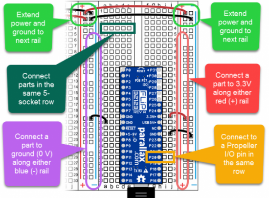

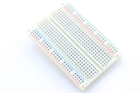
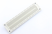
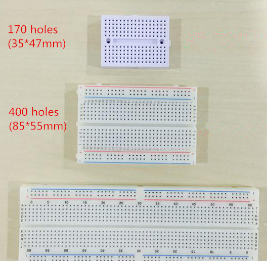
Preview one breadboard usage picture first. And you can learn how the pins connected in one breadboard and how to use it. The following is some basic information about breadboard. What is a breadboard? A breadboard is a rectangular plastic board with a bunch of arrayed tiny holes in it. You can easily insert electronic components into these holes to make up a connective circuit for prototyping or testing. There are different sizes and different colors of breadboards like these. You can visit this page to purchase breadboards in good price.
Breadboard is one of the elemental components when you learn how to build an electric circuit. Because It’s not for permanent circuit connections, you can freely pull out the electronic components from the holes to reconnect or remove the circuit without the need of soldering and assembling, and also importantly it allows the components to be repeatedly used, which makes it perfect for prototyping, debugging and learning electronic circuits. So, for those electronics beginners, breadboard is a great helper to start with. First get yourself a breadboard, and I’m sure you will know how to use it on your own and can’t wait to try experimenting with it after reading through this blog.
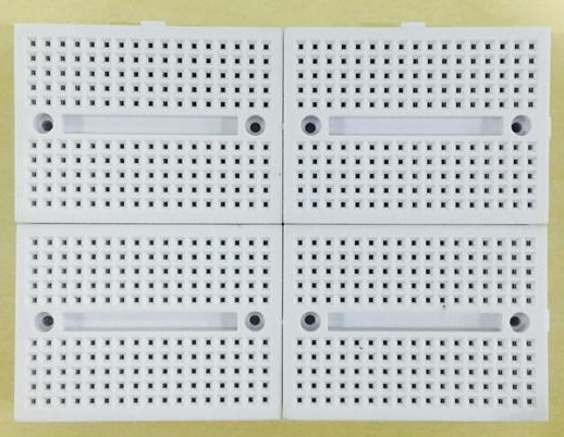
Tips: Normally there is bulges and grooves on the sides of a breadboard which allow you to splice multiple same-sized breadboards together for accommodating various circuits at different degrees of complexity.
![]()
How to use a breadboard?
We know that all uses of the breadboard are based on building circuits, saying if you know how to build a circuit with breadboard, you will know how to use breadboards. Therefore, we must figure out how a breadboard works first, which determines that how you should connect electronic components and jumpers on it to make circuits. Let’s go over this process step by step against a photo of breadboard.
-
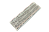
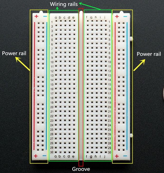
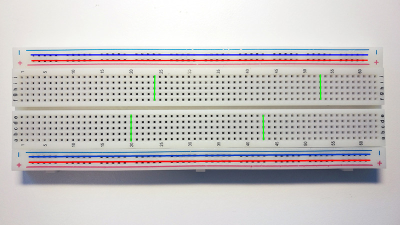
Basically, there are three areas functionally on a breadboard, power rails near the long sides, wiring rails(holes from a to j rows) and the middle groove. And remember that the inside of the breadboard(under the holes) is made up of sets of five metal clips.
-
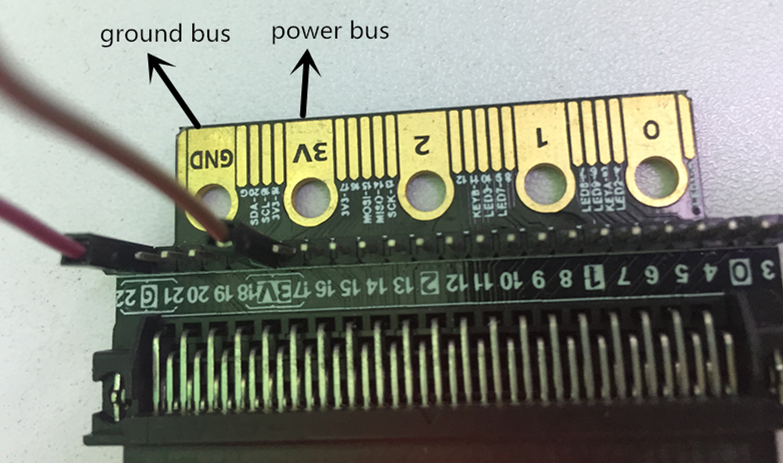
In the power rails areas, the hole strips(highlighted in blue lines below) marked by blue lines and with minus(-) signsare negative buses, correspondingly the hole strips(highlighted in red lines below) marked by red lines and with plus(+) signs are positive buses. They are typically used to supply electrical power to your circuit when you connect them to a battery pack or other external power supply.
-
Note that only holes in the same strip forming a row are electrically connected to each other.
4.Wiring rails are the main workarea, which are separated by the middle groove into two parts(rails a-e and rails f-j). In a similar way, each set of five holes forming a half-column is electrically connected, meaning that hole a1 is electrically connected to holes b1, c1, d1 and e1, but not connected to hole a2, because that hole is in a different column with a separate set of medal clips. Also holes a1- e1 is not connected to holes f1, g1, h1, i1 and j1, because they are electrically separated by the middle groove.
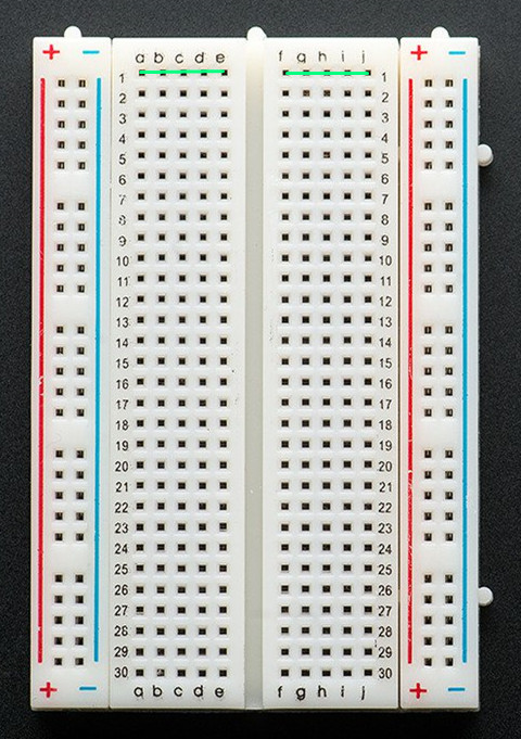
Tips: Holes being electrically connected to each other means that current is unblocked between them once supplying power, so don’t try to connect them with jumper wires or components otherwise you will get short circuit. On the contrary, holes being not electrically connected means current is blocked between them, where you have to insert jumper wires or components to make the circuit work.
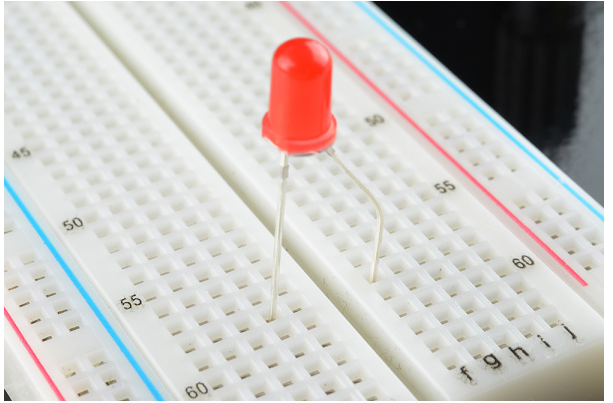
Insert the two leads of LED respectively into either side of the groove, which prevents the short circuit. After understanding the working principle of breadboard, the rest gets easier to go. Now it’s time to get your hands on the physical experiments. Let’s get started with a simple circuit!
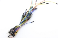
5.Build a simple circuit on breadboard.Project example: lighten a LED Materials: power supply, two jumper wires, a LED, a resistor, and a breadboard
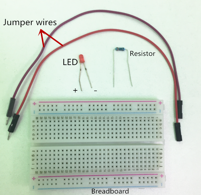
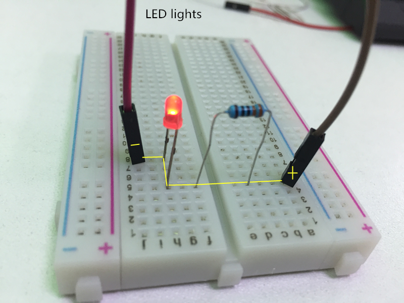
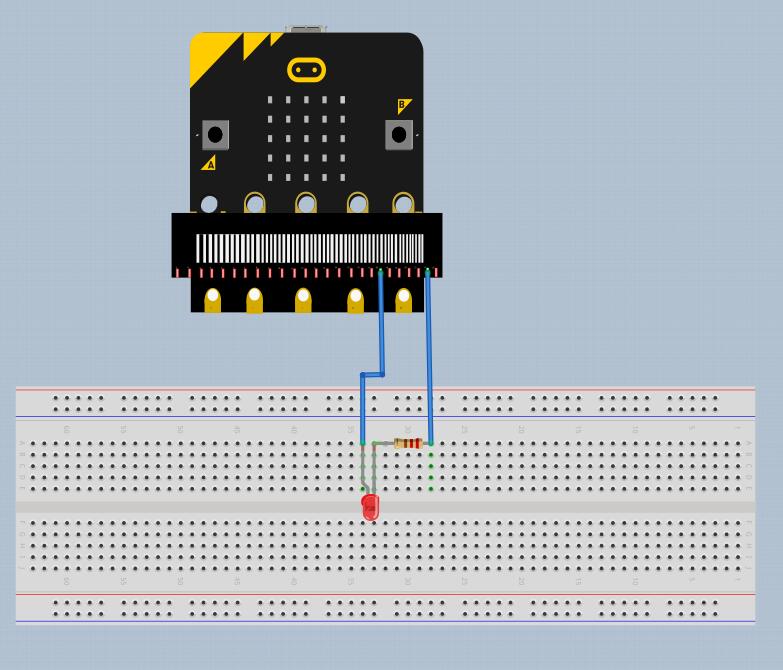
Insert the jumpers and electronic components to build a complete circuit as per the breadboard “holes” rules mentioned above. A complete circuit is done! It's quite easy, is it? Whatever the circuit is, simple or complex, they all are based on the same principle. Also, if you are still worried about building a circuit on your own, following a breadboard diagram will be a good solution. So last but not least, learn to read the breadboard diagram. A breadboard diagram is a computer-generated drawing of a circuit on a breadboard. Every electronic component has a corresponding unique circuit symbol in breadboard diagram. Breadboard diagrams make it easy for beginners to follow instructions to build a circuit because they are designed to look like the "real thing". For example, this diagram (made with a free program called Fritzing) shows a basic circuit with an external power supply, an LED, a resistor, which looks very similar to the above physical circuit

___________________________________________________________
Btw, Raspberry Pi boards are popular and versatile tools for makers. The latest addition to the lineup, Raspberry Pi 5, is the most powerful version yet. Why not upgrade your projects with this cutting-edge device? Join our Giveaway campaign for Elecrow fans to win a brand new Raspberry Pi 5. Don't miss out! Good luck!
Elecrow Monthly RaspberryPi 5 Giveaway