Lesson04: Rotary Encoder and Encoder Button
1. Objectives
In this lesson, you will read the A/B phase signals from the EC04 rotary encoder to detect clockwise and counterclockwise rotation. You will also read the encoder’s built-in button and print button events to the Serial Monitor.
2. Prerequisites
- The ESP32-S3 environment setup in Lesson01 has been completed.
- Additional library:
EncoderTool; this project uses version3.2.2. - Additional library:
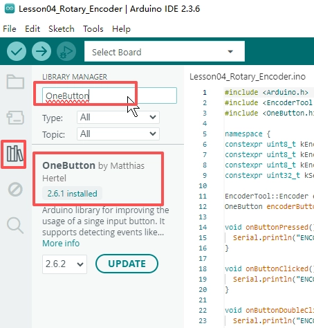
OneButton; this project uses version2.6.1. - Additional library:
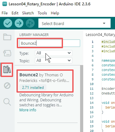
Bounce2; this project uses version2.71and is used in scenarios related to EncoderTool.
How to add the library files:
- EncoderTool: 3.2.2
- OneButton: 2.6.1
- Bounce2: 2.71
- Library download link: https://github.com/Elecrow-RD/CrowPanel_2.01_inch-HMI_ESP32_Watch_Display_240_296/tree/master/example/V1.0/Arduino/Lesson04_Rotary_Encoder
3. Arduino IDE Instructions
-
Open
Lesson04_Rotary_Encoder.inoin the Arduino IDE.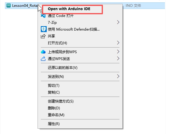
-
Confirm that the board settings are the same as those in Lesson01.
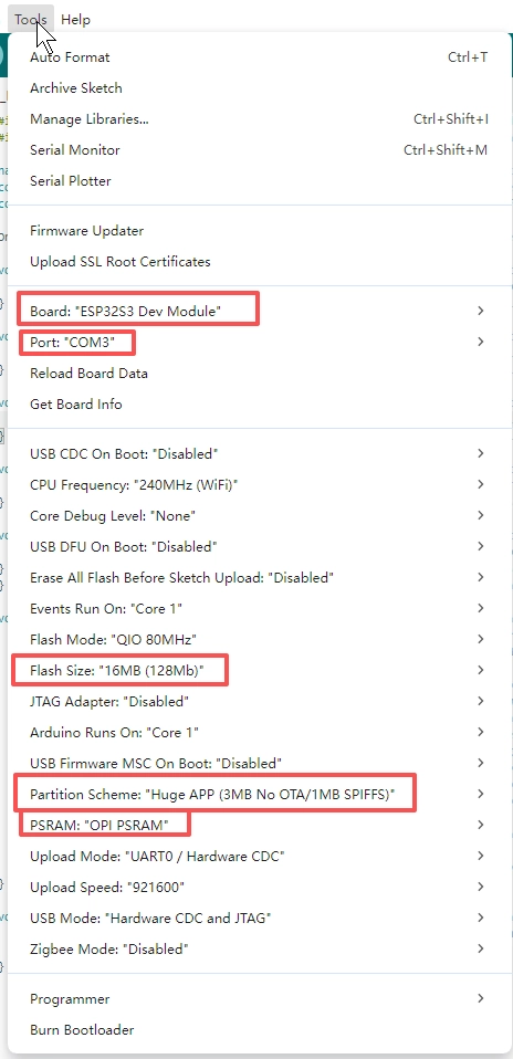
-
Confirm that
Libraries/EncoderTool,Libraries/OneButton, andLibraries/Bounce2exist or have been installed.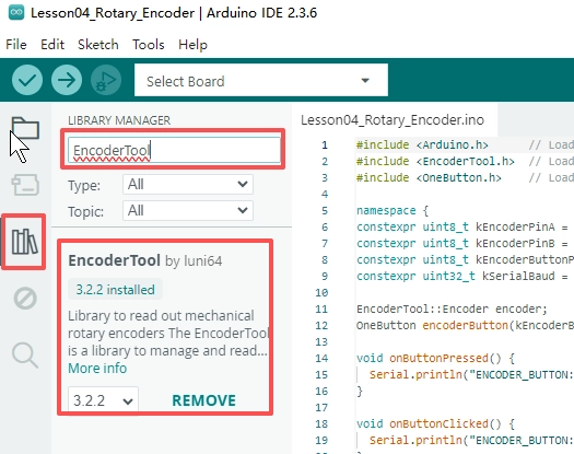
-
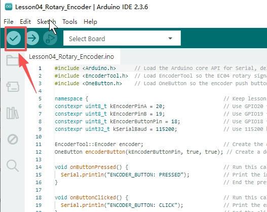
Click Verify to compile the sketch.
-
Click Upload to flash the sketch, open the Serial Monitor, and set the baud rate to
115200.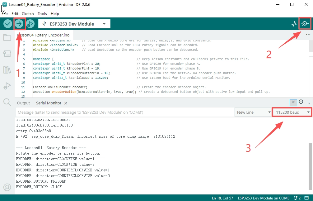
4. Hardware Instructions
- Connect the development board to the computer using a USB data cable and keep the Serial Monitor open.
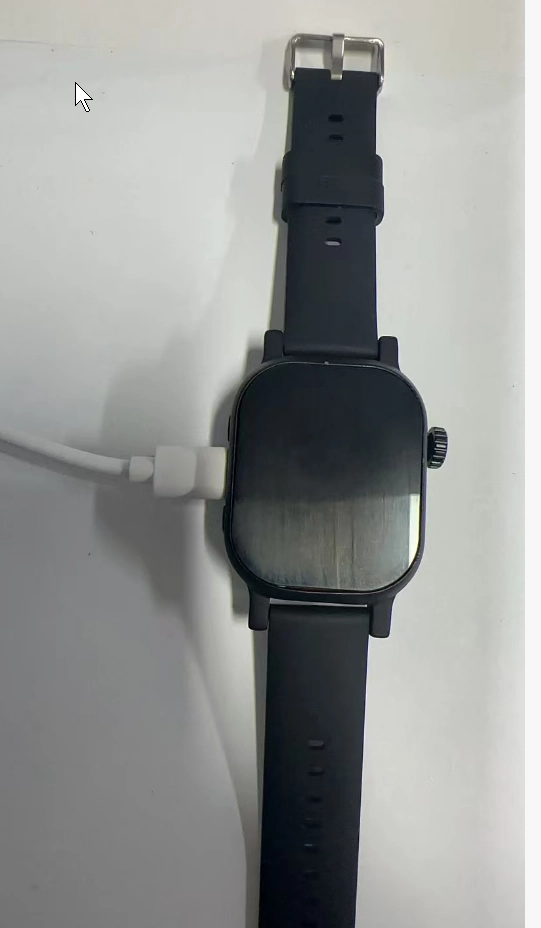
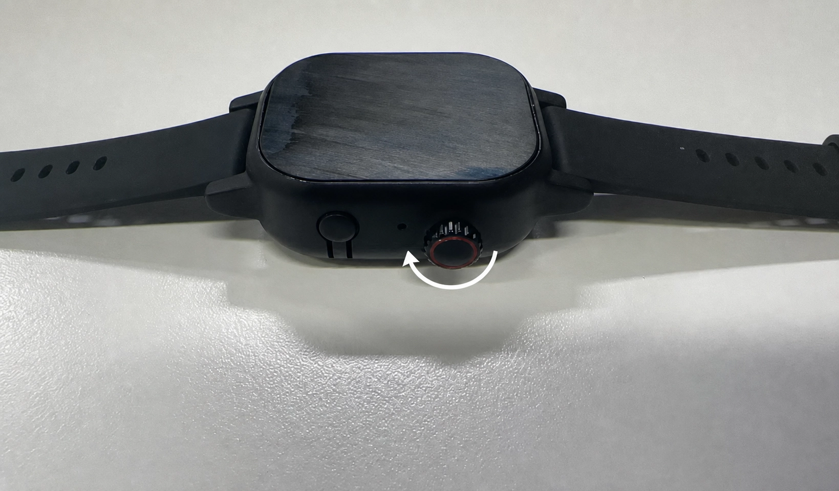
- Rotate the encoder counterclockwise and observe the direction and value changes in the Serial Monitor.
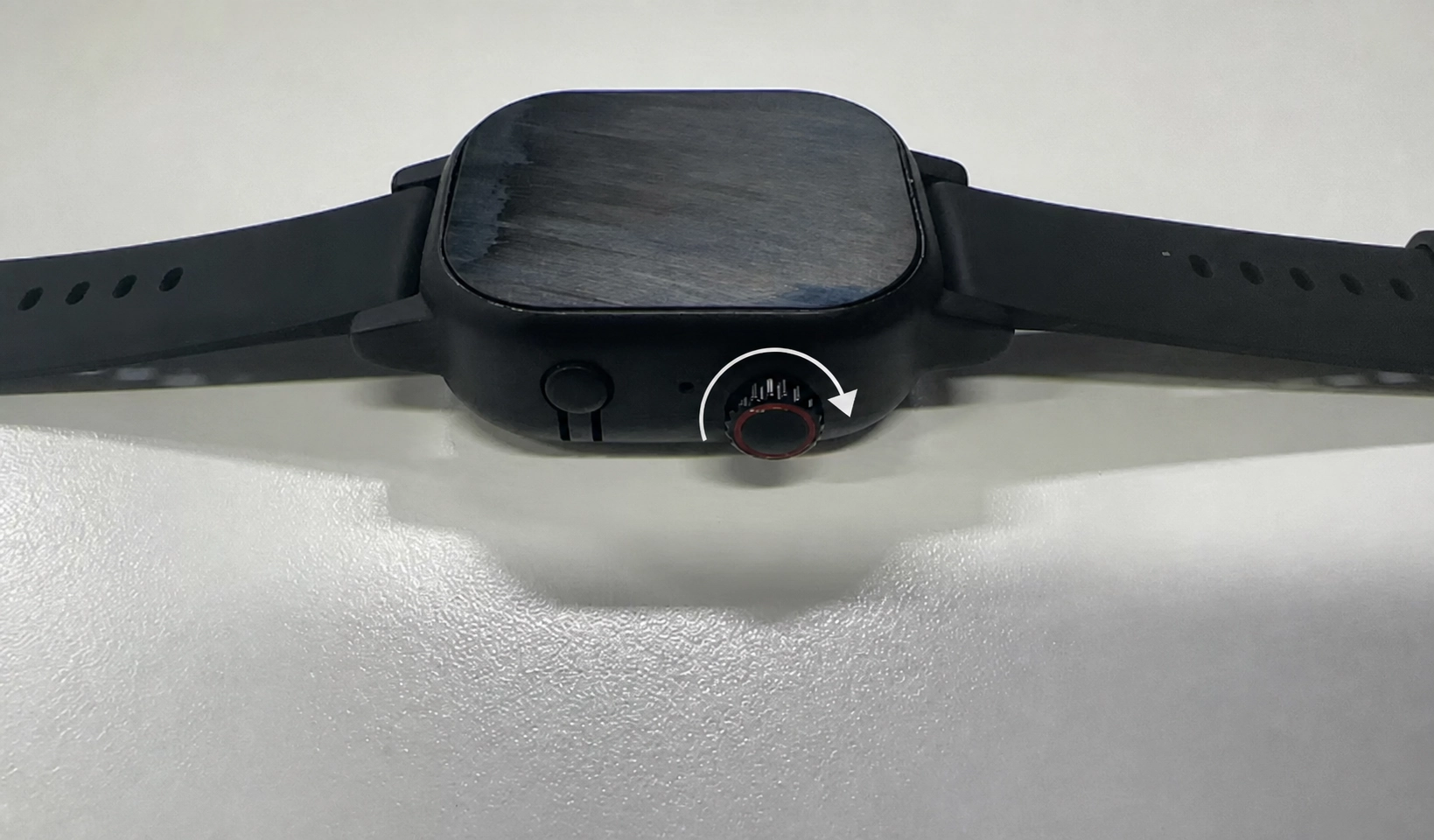
- Rotate the encoder clockwise and confirm that the printed direction changes.
-
Press the encoder button and test the single-click, double-click, and long-press events separately.
-
In this lesson, only the encoder and encoder button are used. The BOOT, Power, and Reset buttons are not tested.
5. Key Code Explanation
constexpr uint8_t kEncoderPinA = 20;
constexpr uint8_t kEncoderPinB = 19;
constexpr uint8_t kEncoderButtonPin = 18;
EncoderTool::Encoder encoder;
OneButton encoderButton(kEncoderButtonPin, true, true);
GPIO20 and GPIO19 are connected to the encoder’s A and B phases, respectively. EncoderTool determines the direction and count based on changes in the two phase signals. GPIO18 is connected to the encoder button. The button is also active-low, so true, true is used in the OneButton constructor.
encoder.begin(kEncoderPinA, kEncoderPinB);
encoderButton.attachPress(onButtonPressed);
encoderButton.attachClick(onButtonClicked);
encoderButton.attachDoubleClick(onButtonDoubleClicked);
encoderButton.attachLongPressStart(onButtonLongPressed);
encoder.begin() starts A/B phase decoding. The following four lines bind the encoder button’s different events to callback functions. This keeps the rotation and button functions independent: the encoder handles position changes, while OneButton handles button actions.
if (encoder.valueChanged()) {
  const long value = encoder.getValue();
  static long previousValue = 0;
  const char* direction = value > previousValue ? "CLOCKWISE" : "COUNTERCLOCKWISE";
  Serial.printf("ENCODER: direction=%s value=%ld\n", direction, value);
  previousValue = value;
}
This code prints only when the encoder value changes, preventing repeated messages from flooding the Serial Monitor. The program compares the current value with the previous value: a larger current value indicates clockwise rotation, while a smaller value indicates counterclockwise rotation. After printing, it updates previousValue in preparation for the next comparison.