Lesson 12: Playing a Test Tone Through an I2S Speaker
1. Objectives
In this lesson, the ESP32-S3’s I2S peripheral generates a 440 Hz sine wave and plays it through the onboard amplifier and speaker. The program does not rely on audio files; instead, it generates PCM data in real time within the code.
2. Prerequisites
- Complete the ESP32-S3 environment setup in Lesson01.
- This lesson uses the built-in
ESP_I2Slibrary from Arduino-ESP32. No additional third-party libraries are required.
How to add the library:
- No additional third-party libraries are required. This lesson uses the ESP_I2S library included with the ESP32 3.3.3 board package.
3. Arduino IDE Instructions
-
Open
Lesson12_Speaker_Playback.inoin Arduino IDE.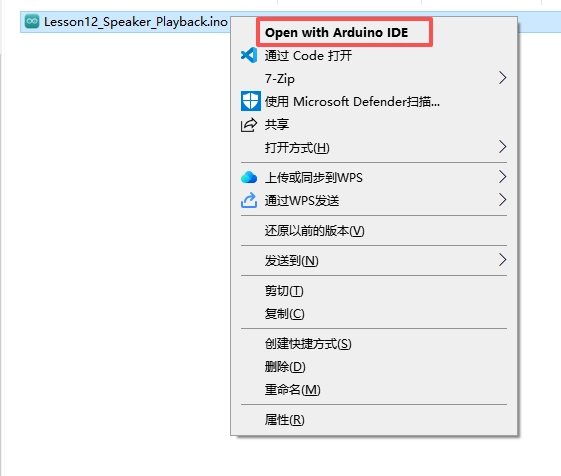
-
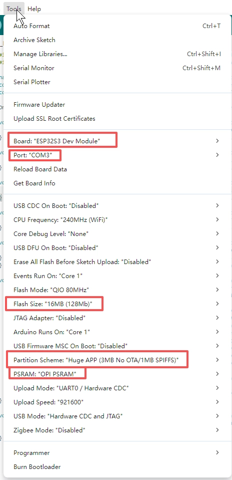
Confirm that the board settings match those used in Lesson01.
-
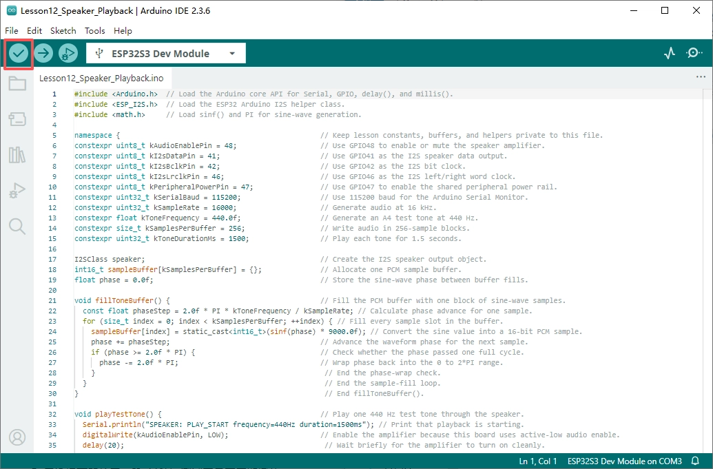
Click Verify to compile the program.
-
Click Upload to flash the program, then open Serial Monitor and set the baud rate to
115200.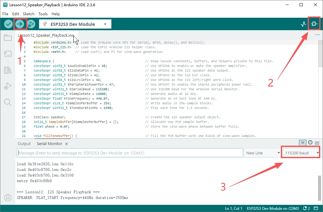
4. Hardware Instructions
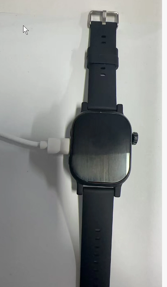
- Connect the development board to the computer using a USB data cable and ensure that the device remains properly powered.
-
After flashing the program, listen near the speaker to determine whether the 440 Hz test tone plays periodically.
-
Observe the PLAY_START and PLAY_END messages in the serial output to confirm the playback cycle.
-
If you cannot hear any sound, verify that the amplifier enable pin, peripheral power supply, and speaker connections are functioning properly.
5. Key Code Explanation
speaker.setPins(kI2sBclkPin, kI2sLrclkPin, kI2sDataPin);
speaker.begin(I2S_MODE_STD, kSampleRate, I2S_DATA_BIT_WIDTH_16BIT,
              I2S_SLOT_MODE_MONO);
I2S requires at least three signal lines: BCLK, LRCLK, and DATA. setPins() assigns the GPIO pins in the order BCLK, LRCLK, and DOUT. begin() configures standard I2S mode, a 16 kHz sample rate, 16-bit samples, and mono output.
const float phaseStep = 2.0f * PI * kToneFrequency / kSampleRate;
for (size_t index = 0; index < kSamplesPerBuffer; ++index) {
  sampleBuffer[index] = static_cast<int16_t>(sinf(phase) * 9000.0f);
  phase += phaseStep;
}
Sound is essentially a sequence of PCM samples. Here, the phase increment for each sample is calculated from the frequency and sample rate, and sinf() is then used to generate a sine wave. Multiplying by 9000.0f controls the volume and prevents distortion caused by approaching the maximum value of 16-bit PCM.
digitalWrite(kAudioEnablePin, LOW);
speaker.write(reinterpret_cast<uint8_t*>(sampleBuffer), sizeof(sampleBuffer));
digitalWrite(kAudioEnablePin, HIGH);
The amplifier enable signal on this board is active-low. Therefore, GPIO48 is pulled low before playback and pulled high after playback to disable the amplifier. speaker.write() accepts a byte pointer, so the int16_t PCM array must be converted to uint8_t* before being passed to it.