Elecrow nRFLR1121 Wireless Transceiver Module -Integrates Nordic nRF52840 and Semtech SX1121 2.4G Band Transceiver Application Document
This document provides a detailed introduction on how to use the ''RadioLib'' library to implement 2.4G band LoRa packet transmission and reception functionality based on the nRFLR1121 module. The solution includes example code for both transmission and reception. The transmitter periodically sends data packets, while the receiver listens in real-time and processes the received packets. By configuring the module parameters appropriately, data can be transmitted stably and accurately over the 2.4G band.
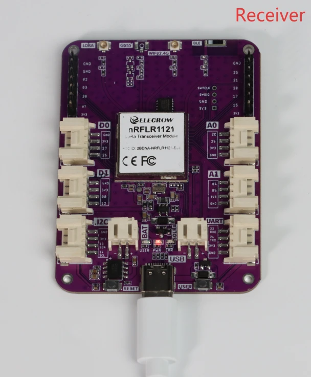
As shown in the figure below, prepare two nRFLR1121 modules and connect them to the computer respectively. After uploading the code, you can view the data sent by the transmitter on the receiver.

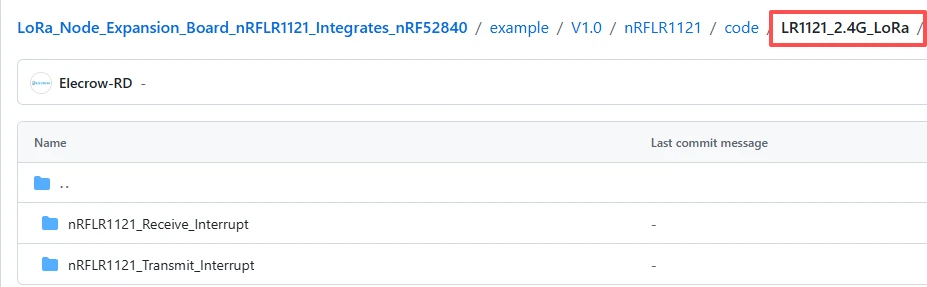
The GitHub download link for the code of this lesson is:
The "nRFLR1121_Transmit_Interrupt" file is used for sending data.
The "nRFLR1121_Receive_Interrupt" file is used for receiving data.
Sender
Let's first take a look at the code on the sender side
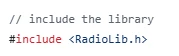
The first line: #include
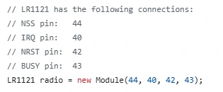
The middle comment clearly indicates the 4 key pins required for LR1121 to communicate and control with the MCU - NSS (SPI chip select), IRQ (interrupt), NRST (reset), BUSY (busy status), and their corresponding pin numbers 44, 40, 42, 43. This clarifies the hardware wiring basis;
LR1121 radio = new Module(44, 40, 42, 43) creates an instance of the LR1121 chip named radio using the Module class from the RadioLib library in the specified pin order. This establishes a binding between the software object and the hardware chip, laying the foundation for subsequent calls to radio.begin(), radio.setFrequency(), etc., and the pin numbers must be consistent with the actual hardware wiring; otherwise, the chip will not be able to communicate normally.
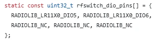
The DIO5 and DIO6 pins of the LR1121 chip are designated as the RF switch control pins through the rfswitch_dio_pins array. The remaining pins are not connected.
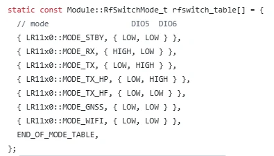
Furthermore, through the rfswitch_table mode table, the high and low level states of DIO5 and DIO6 pins under different working modes such as standby, reception, transmission, GNSS, and WiFi are defined. This enables the chip to automatically switch the RF path to achieve normal wireless transmission and reception as well as functional switching.
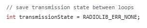
Finally, the global variable "transmissionState" is defined to store and transfer the status codes during the data packet transmission process, facilitating the program to determine whether the transmission was successful.
This code is the initialization entry function of the program, named "setup()". It is executed only once upon startup. Its main function is to complete serial port debugging, SPI communication pin configuration and startup, laying the foundation for subsequent communication of the LR1121 wireless module:
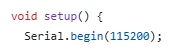
Firstly, through Serial.begin(115200), the serial port communication is initialized with a baud rate of 115200, which is used for viewing the program's operation log on the computer. The commented parts are optional serial port waiting logic;
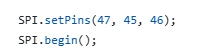
then, call SPI.setPins(47, 45, 46) to manually specify the hardware SPI pins (corresponding to the SPI clock, data input, and data output pins respectively). Finally, execute SPI.begin() to start the SPI bus, and SPI is the core protocol for communication between the microcontroller and the LR1121 chip, which is a necessary prerequisite for driving the wireless module.
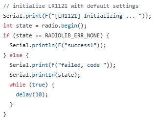
After printing the prompt information through the serial port, call radio.begin() to start the module and obtain the status value. If the return value is RADIOLIB_ERR_NONE, it indicates that the initialization is successful and the serial port prints a successful prompt; if it returns any other error code, print the failure information and enter a dead loop to freeze the program, avoiding the program continuing to run when the module is not working properly.
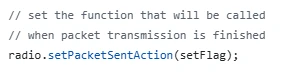
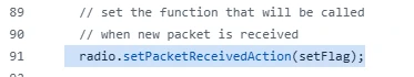
This line of code is used to set the data packet transmission completion interrupt callback function for the LR1121 wireless module. By binding the custom setFlag function to the module's transmission completion interrupt event, it achieves that when LR1121 automatically completes the data packet transmission, it will immediately trigger the execution of the setFlag function through the hardware interrupt, thereby marking the transmission completion status. This is the core configuration for implementing non-blocking interrupt-based transmission, allowing the main program to execute other tasks without waiting for the transmission process.
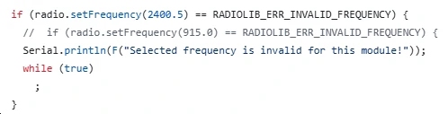
This code is used to set the LoRa working frequency of the LR1121 module to 2400.5 MHz. The function will return the setting result. If the detected frequency is illegal, it will output an error message via the serial port and enter a dead loop to stop the program from running.
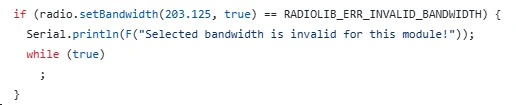
This code is used to set the LoRa signal bandwidth of the LR1121 module to 203.125 kHz. At the same time, it verifies the configuration result. If it detects that the bandwidth parameter is invalid, it will print an error message via the serial port and enter a dead loop to terminate the program.
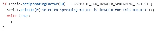
This code is used to set the LoRa spread spectrum factor of the LR1121 module to 10. The function returns the setting status. If the spread spectrum factor value detected is invalid, an error message will be output via the serial port and the program will enter a dead loop to stop running.
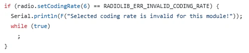
This code sets the LoRa encoding rate of the LR1121 module to 6. The function returns the setting status. If the encoded rate value detected is invalid, it will output an error message via the serial port and enter a loop to stop the program from running.
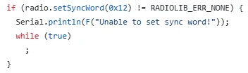
This code sets the LoRa synchronization word of the LR1121 module to 0x12, which is used to identify the communication network. If the setting fails, it prints the error message via the serial port and enters an infinite loop.
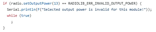
This code sets the transmission power of the LR1121 module to 13 dBm. The function returns the setting status. If the detected output power value is invalid, it will output an error message via the serial port and enter a dead loop to stop the program from running.
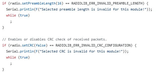
This code first sets the LoRa preamble length of the LR1121 module to 16. If the check fails, it will report an error and freeze. Then, it turns off the CRC data verification function and also verifies the configuration result. If it fails again, it will output an error and enter an infinite loop.
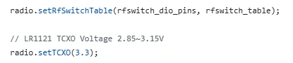
This code loads the previously defined RF switch pins and the mode table into the LR1121 module, enabling the chip to automatically control the switching between transmission and reception. At the same time, it sets the supply voltage of the TCXO crystal oscillator to 3.3V to ensure the stable operation of the module's clock.
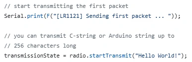
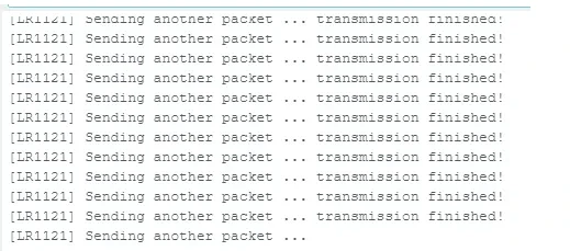
This code first prints a prompt message via the serial port to indicate that the first data packet is being sent. Then, it calls the "startTransmit" function to start the LoRa asynchronous transmission, sends the string "Hello World!" and saves the transmission status to the "transmissionState" variable.
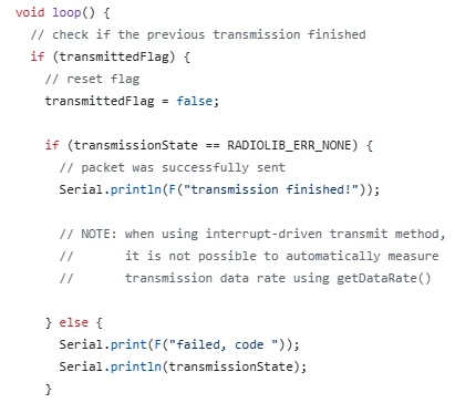
The "loop()" function is the main loop body of the Arduino program, which will execute in an infinite loop. Its core function is to implement non-blocking periodic LoRa data transmission for the LR1121 module based on the interrupt flag:
The function first checks whether the transmittedFlag interrupt flag is set, thereby determining whether the previous data packet has been sent successfully. If the flag is valid, it first resets it, then determines the success of the transmission based on the transmissionState stored sending status code, and prints the corresponding success prompt or error code through the serial port.
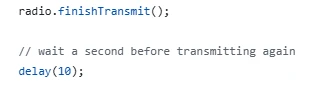
Then, it calls the "radio.finishTransmit()" function to complete the post-transmission operations, turns off the transmission circuit, resets the RF switch to reduce power consumption and ensure the module is in a normal state, and then delays for 10 milliseconds to control the transmission interval.
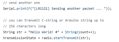
Next, it constructs a string data containing an incremented count number. Finally, it calls the "startTransmit()" function to start the next round of asynchronous transmission and store the new transmission status in a variable, thereby achieving the complete process of the module continuously and non-blockingly sending LoRa data packets.
Receiver
Most of the initialization code at the receiving end is consistent with that of the sending end. Here, we mainly explain the receiving function code at the receiving end.
This line of code is used to register the data packet reception interrupt callback function for the LR1121 wireless module. It binds the custom setFlag function with the module's hardware reception interrupt event. When the module successfully detects and completely receives a LoRa data packet that matches the communication parameters, it will automatically trigger the execution of the setFlag function through the hardware interrupt, setting the reception flag to true. This achieves interrupt-driven non-blocking reception, allowing the main program to know when the data arrives without continuously polling for detection.
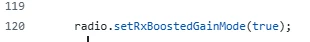
This line of code is used to activate the "Receiving Enhanced Gain Mode" of the LR1121 module. After setting the parameter to true, the module will increase the receiving sensitivity and enhance the processing capability for weak signals, enabling the device to capture and interpret LoRa signals over a longer distance and with greater stability. This mode is particularly suitable for long-distance communication or scenarios with poor signal conditions.
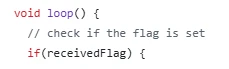
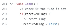
This is the main loop function of the LR1121 receiving program. The program will execute in an infinite loop. The core is to achieve efficient non-blocking LoRa data reception processing through the interrupt flag:The function first checks whether the receivedFlag flag is set to true, thereby determining whether the module has received a new data packet through the hardware interrupt.
When valid data is detected, the flag is immediately reset to avoid duplicate processing.
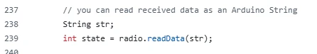
Then, the readData function is called to read the received data as a string format and obtain the reception status.
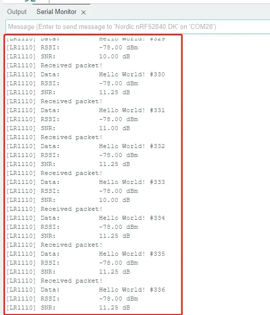
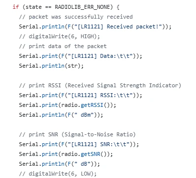
Subsequently, the status is judged and processed - if the status is successful, the received success prompt, complete data content, signal strength RSSI, and signal-to-noise ratio SNR are printed through the serial port.
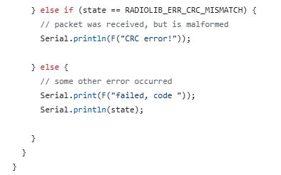
If the status is CRC error, indicating incomplete data reception or interference, an error message is printed. For other abnormal situations, the corresponding fault code is output. All processing is completed and the program returns to the beginning of the loop to continue waiting for the next reception interrupt.
The entire process does not require polling and listening, and does not occupy system resources, achieving real-time, stable, and automatic LoRa data reception and parsing.
Notes:
1.Install the development version
Lastly, here are some points to keep in mind during actual operation:Since the nRFLR1121 uses the nRF52840 as the main control chip, you need to install the nRF52 development board.
Open the Arduino IDE.
Go to File > Preferences (or Arduino > Preferences, depending on your operating system).
In the "Additional Board Manager URLs" field, add the following URL:
https://adafruit.github.io/arduino-board-index/package_adafruit_index.json
If there are already other URLs, make sure to separate them with commas or new lines.
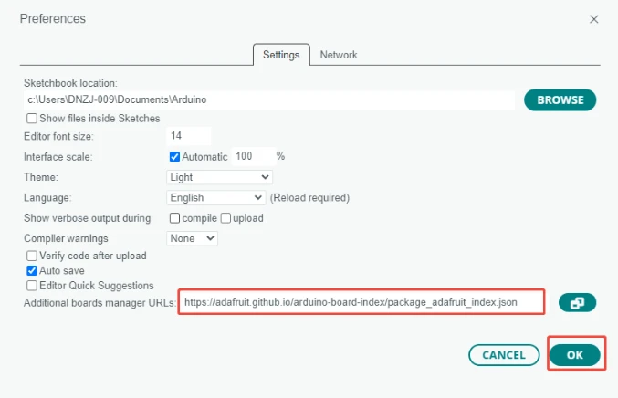
Click "OK" to save the settings.
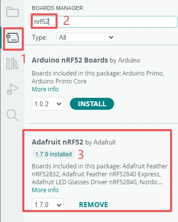
Navigate to Tools > Board > Boards Manager.
In the search box, type "Adafruit nRF52", find "Adafruit nRF52 by Adafruit", and click "Install".(Here we are using version 1.7.0.)
Once installation is complete, you can select the appropriate board model from the Tools > Board menu.
2.Use the library files we provided
Click on the link to our library file for download:
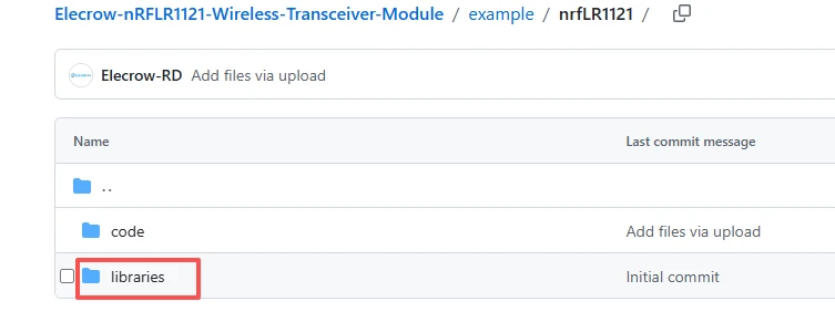
After the download is complete, place these four library files in this directory on your computer.
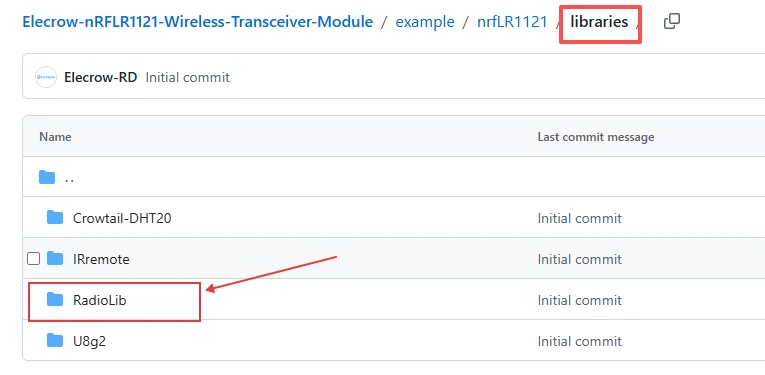
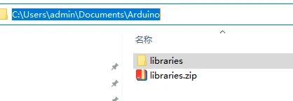
Place these four library files in the following path on your computer, in the "libraries" folder.
3.Pay attention to the configuration during the flashing process.
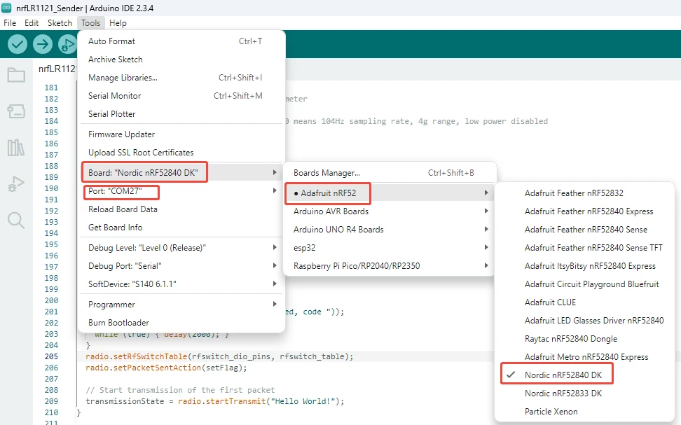
Result:
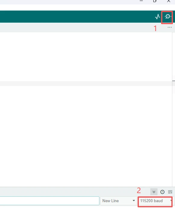
By examining the information printed via the serial port, one can observe the status information of data transmission and reception.Open the serial monitor that comes with Arduino IDE and set the baud rate to the value specified in the code, which is 115200.
Data sent successfully from the transmitter
Data printed from the receiver’s serial port