Quick Network Configuration of Gateway-ThinkNode Gateway and nRFLRCC68 Module
1. Description
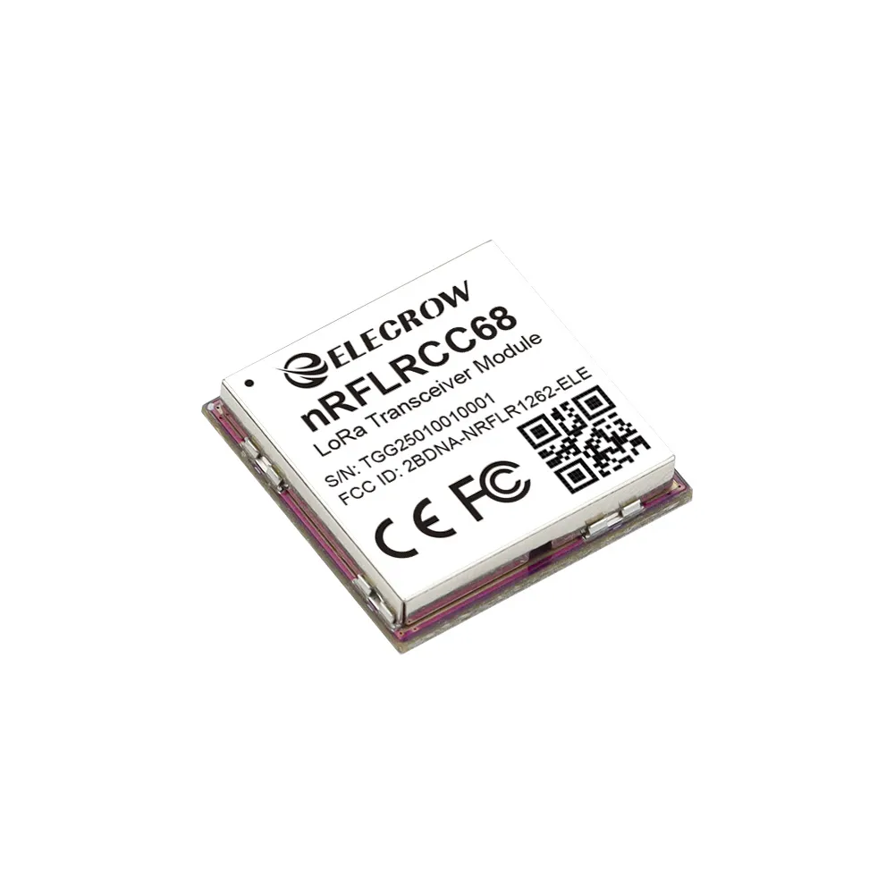
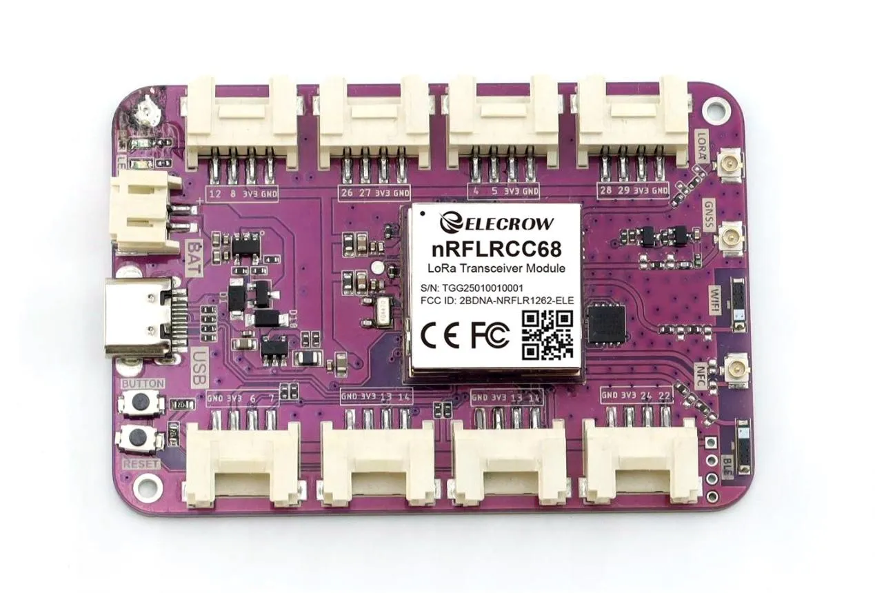
The Elecrow nRFLRCC68 module integrates the Nordic nRF52840 microcontroller and the Semtech LLCC68 LoRa transceiver chip. It is a high-performance, low-power medium- and long-range transceiver module. It supports Bluetooth 5.3 and low-power Bluetooth, complies with the A, B, and C classes of the LoRaWAN 1.0.4 specification, and supports LoRa point-to-point (P2P) communication mode. It covers the 850~930MHz (applicable to 868MHz, 915MHz) global ISM band, with a maximum transmit power of +20dBm, a transmission rate range of 1.76~62.5Kbps, and a transmission distance of up to 10 km.
The nRFLRCC68 module has built-in AT command firmware, supports SDK customized development, and a rich peripheral interface that provides high flexibility to meet diverse development needs. The nRFLRCC68 module retains the advantages of low power consumption, high transmit power and full LoRa frequency band, while optimizing the cost structure, removing the less used "ultra-low rate scenario", achieving significant price advantages, making it more suitable for smart home applications, medium-range indoor and indoor-to-outdoor wireless applications.
Self-developed by Elecrow with exclusive design. Customization can be discussed for bulk orders.
For customized requirements (based on MOQ), please contact us at service@elecrow.com.
2. Features
-
High performance: Maximum transmit power can reach +20dBm, support 1.76~62.5Kbps transmission rate, -125.5dBm sensitivity SF12/BW=125kHz, 151db link budget;
-
Ultra-low power consumption, sleep current is only 5uA;
-
Support 850~930MHz global LoRa&LoRaWAN ISM frequency, support LoRa point-to-point (P2P) communication; nRF52840 Bluetooth 5.3 SoC, support low-power Bluetooth, Bluetooth mesh network, NFC, Thread and Zigbee;
-
Long-distance communication, the communication distance can reach 10km;
-
Built-in AT command firmware and support the use of SDK for customized product development, and the AT command set can be easily used through the UART interface;
-
Rich peripherals, the module leads to a variety of GPIO interfaces such as UART, I2C, ADC, etc., providing great flexibility;
-
Compact form factor with only 20x 20x 3.5 mm
-
FCC, CE, RoHS certification
3. Network Configuration of Gateway
Configure the gateway's networking method: Three networking methods are available: Ethernet, Wi-Fi, and 4G cellular (applicable only to the 4G version). Here, the Wi-Fi mode is used.
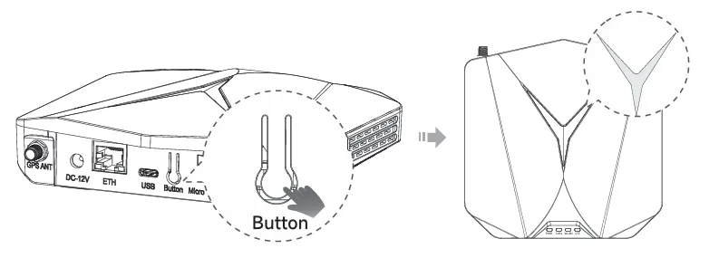
STEP1:Turn on the device's AP hotspot
Press and hold the button for 5 seconds until the top indicator light slowly flashes blue, then it will enter configuration mode.
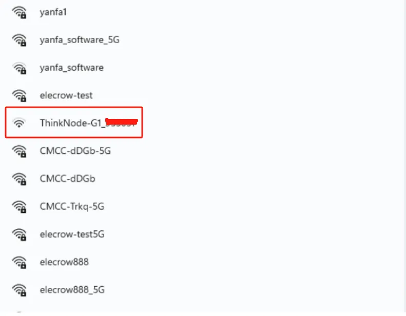
STEP2:Connect to the AP hotspot
The name of the AP hotspot is ThinkNode - G1_XXXXXX (6 - digit MAC address). No password is required, and you can connect directly. Connect your computer or mobile phone to this AP hotspot.
STEP3:Log in to the local console
Enter the IP address (192.168.1.1) in your browser to access the local console. Then log in with the username "root", enter the password "root", and click the "Login" button.

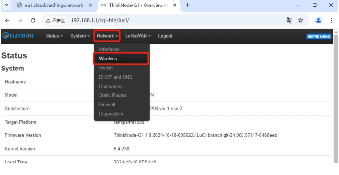
STEP4:Log in to the Luci page, and click Network - Wireless
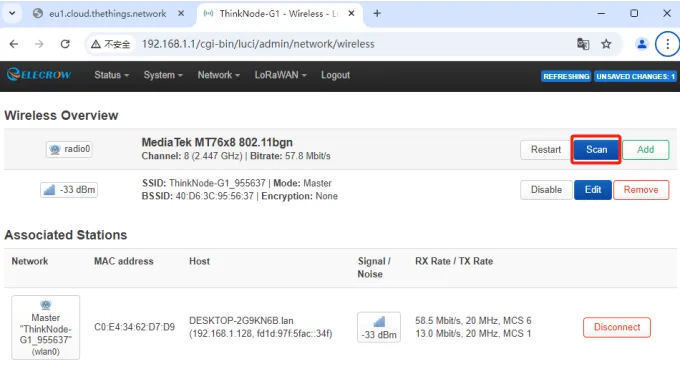
STEP5:Click the "Scan" button to scan for Wi - Fi.
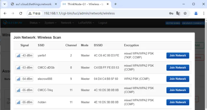
STEP6:Select your Wi - Fi to join the network.
STEP7:Enter the Wi-Fi password, then click "Submit", and save the settings.


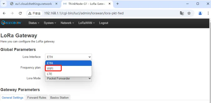
STEP8:Set the gateway's Internet connection method to Wi-Fi.
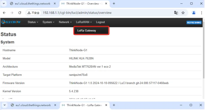
On the Luci interface, click "LoRaWAN" and navigate to the LoRa Gateway interface.
Select the network configuration mode as "WiFi".
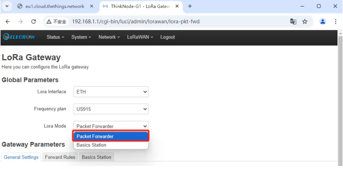
STEP9:Set Mode to Packet Forwarder
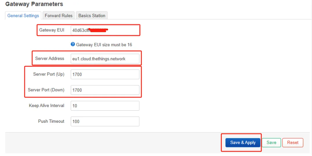
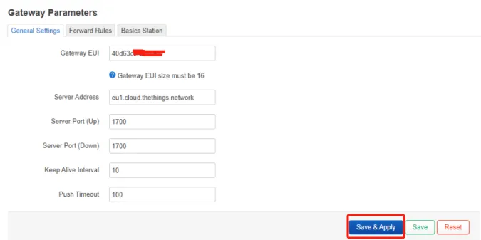
STEP10:Packet Forwarder Settings
1.Gateway EUI: It will automatically obtain the EUI of the connected gateway.
2.Server address: For the Semtech UDP packet forwarder, use "server-address". "server-address" is the address of The Things Stack deployment.
3.Server Ports (Up/Down): The uplink and downlink ports are typically set to 1700.
Other settings can be left as default or adjusted according to your requirements.
STEP11:Channel Plan Settings
Select the Region and Frequency plans according to the actual situation.This lesson takes EU868 as an example, so select EU868 here.
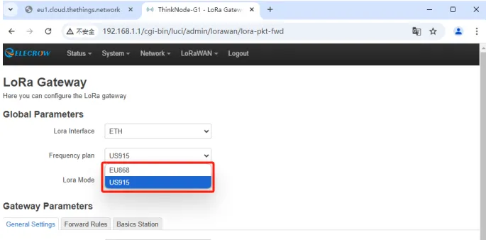
Then click "Save & Apply" to apply your settings.
Note: Remember the Gateway EUI here, which needs to be filled in on the TTN platform later.
Double-click the reset button and wait for the device to restart. If the gateway successfully connects to the Wi-Fi, the WLAN green indicator light will remain steadily on, and the top indicator light will also show a steady green glow.
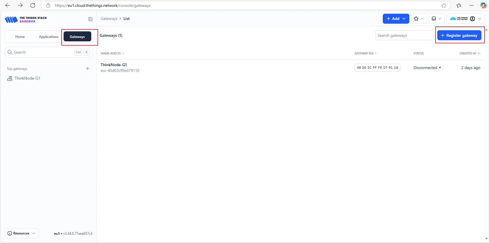
4. Deployment of the G1 gateway on the TTN platform
STEP1:Log in to The Things Stack (console.cloud.thethings.network). If you don't have a TTN account, please register first.

STEP2:Register the gateway, fill in the EUI, and click "confirm".
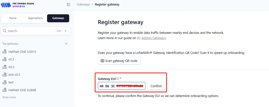
Gateway ID: It typically consists of letters (eui - "Gateway EUI") (The ID must contain only lowercase letters, numbers, and dashes).Note that the letters in "Gateway EUI" must be converted to lowercase.>
Gateway Name: The name of the gateway.
Frequency Plan: Select the corresponding frequency according to your gateway version.

After successful registration, you can view the gateway in the overview.
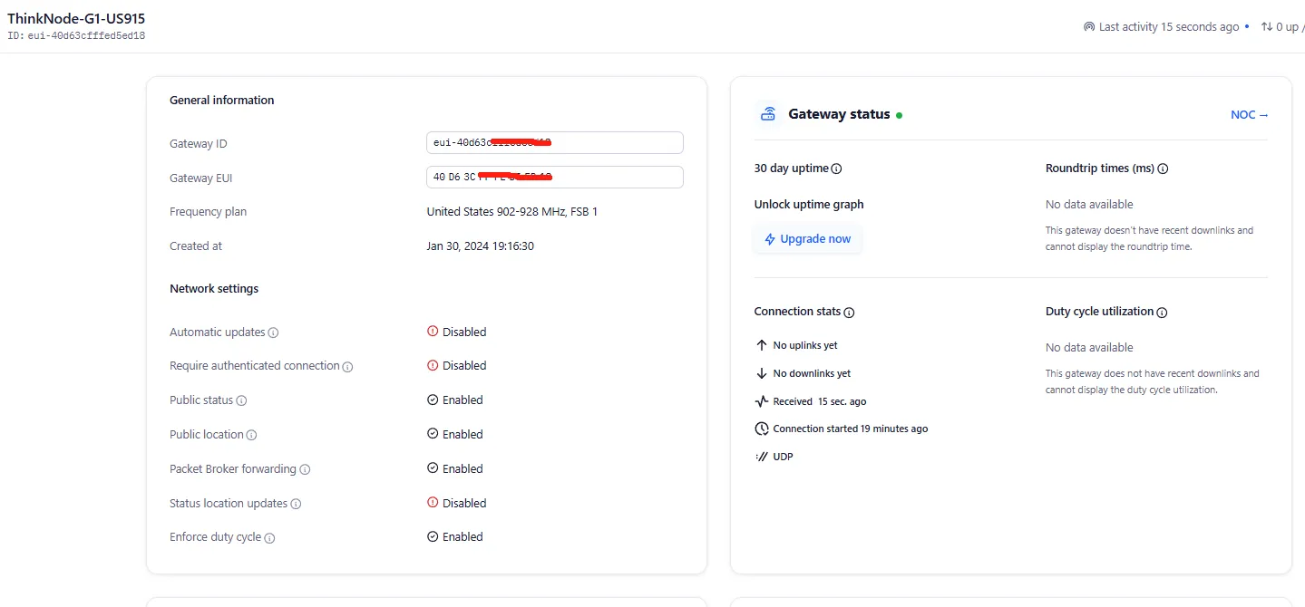
Double - click the gateway settings button and wait for the gateway to restart. The gateway is now connected to TTN as a Packet Forwarder.
5. Create a TTN node application
STEP1:Log in to the registered TTN account.
In the TTN server interface, click "Applications".

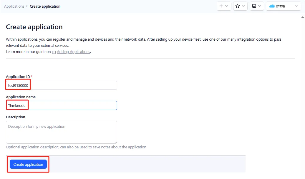
STEP2:Click "Add application" to start adding a node application.
Enter the Applications ID and Applications name, then click "Create application".
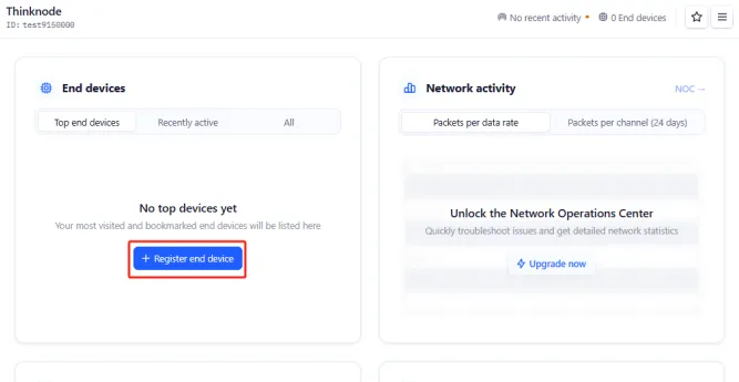
STEP3:Enter the application overview page, click "Register end device" in the lower - left corner to register a new device on the TTN platform.
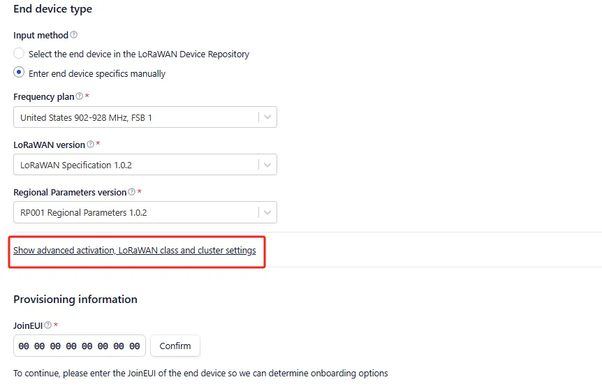
STEP4:In the "Register end device" page, click the "Enter end device specifics manually" option.

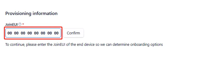
STEP5:Set the Frequency plan, LoRaWAN version, Regional Parameters version, and JoinEUI (APPEUI).
Note: JoinEUI is the same as AppEUI.>

Set the Frequency plan.Note that the frequency band range should be consistent with that of the gateway you are using.

Set the LoRaWAN version.
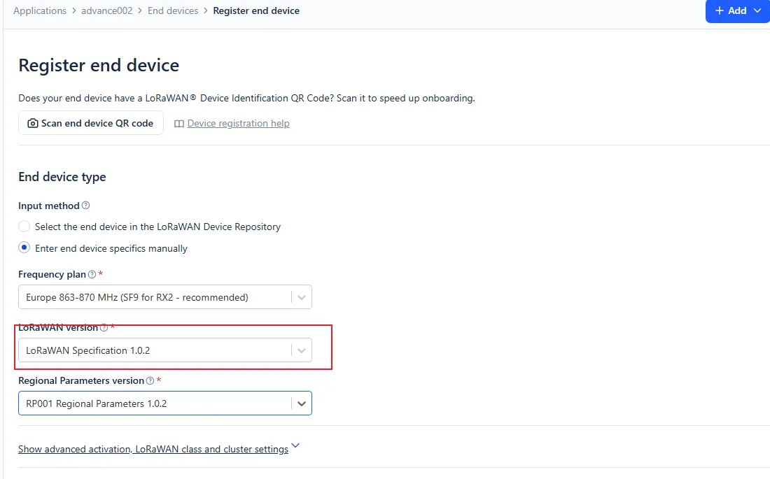
Set the Regional Parameters version.

Set the JoinEUI (APPEUI).
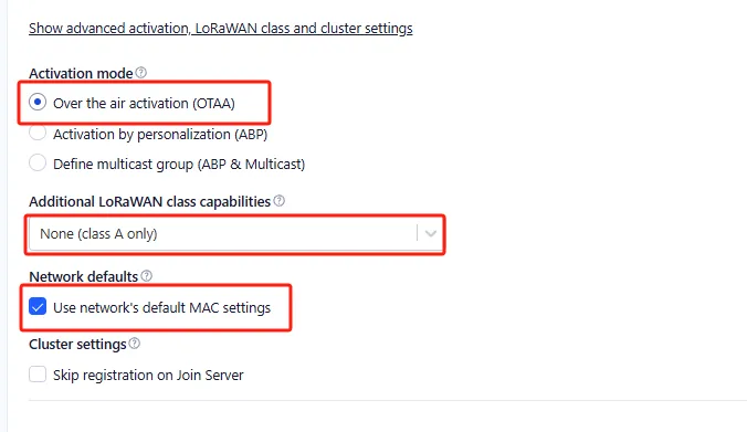
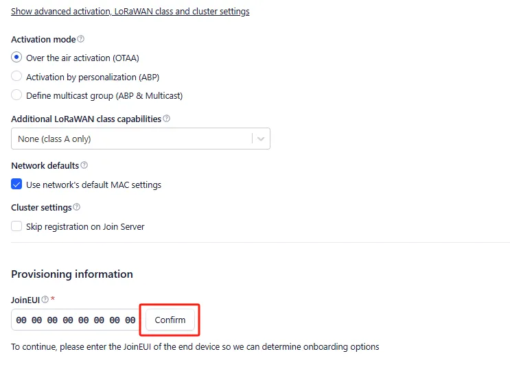
STEP6:Click "Show advanced activation, LoRaWAN class and cluster settings" to configure parameters such as the activation mode and the device operating mode.
· When the activation mode is OTAA
Configure it to OTAA mode (i.e., the default mode).
Then click "Confirm".
STEP7:According to the activation mode selected above, configure the corresponding device parameters as shown in the following figure:
Click "Generate" to automatically generate the DevEUI.
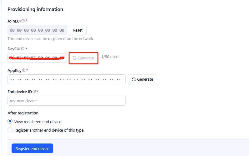
Click "Generate" to automatically generate the AppKey.
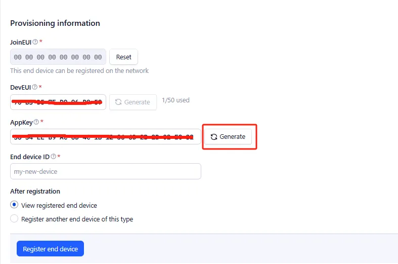
Enter the End device ID.
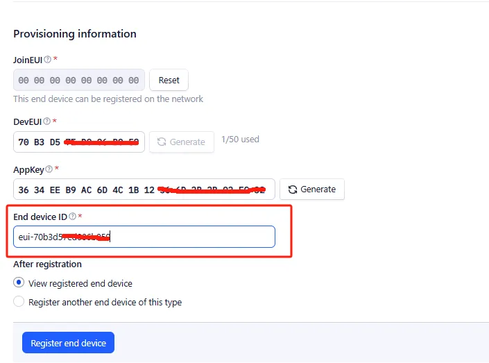
Click "Register end device".

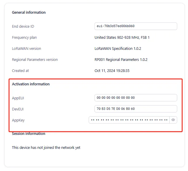
The OTAA device registration was successful.
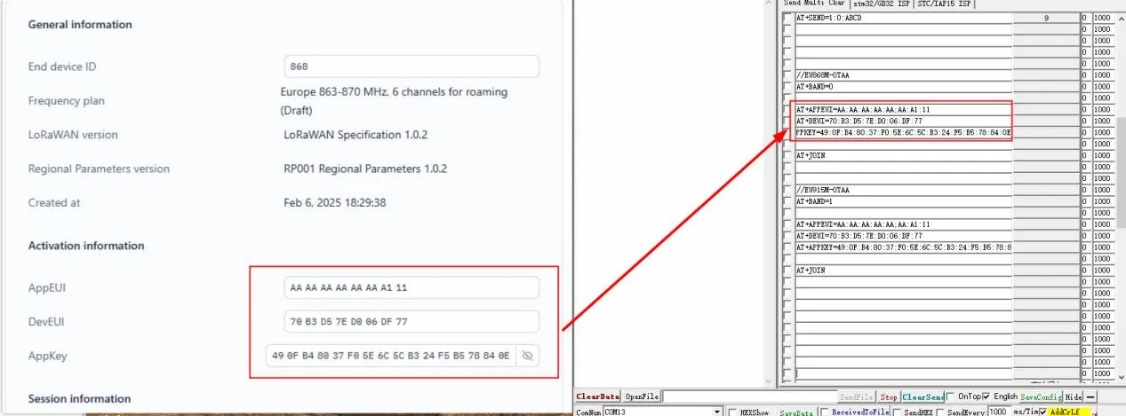
Note: Save the content in the Activation information, which will be used when sending AT commands later.
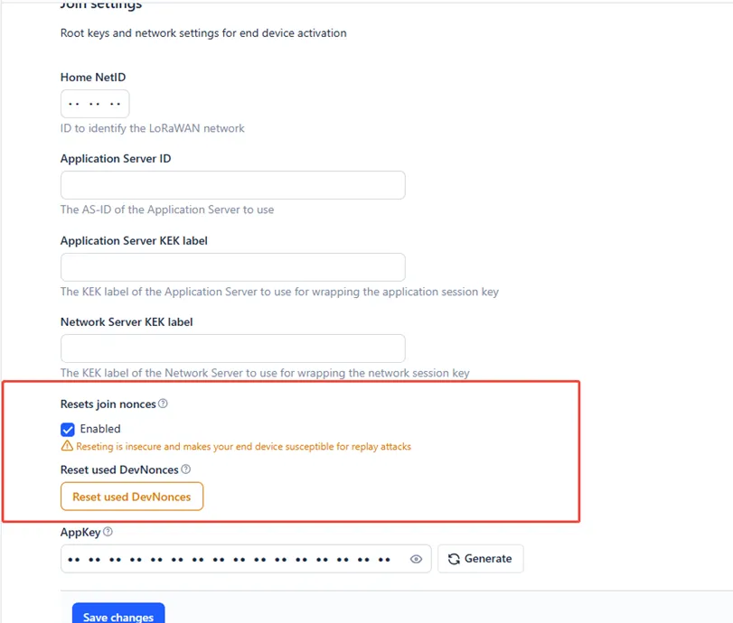
Note: Since LoRaWAN does not allow repeated use of network access, when the used DevNonce is ignored, the node can test network access indefinitely.
Click on Application -> Application Name

Click on node name->Settings

Pull down to the bottom of the page, Select Join Settings.

Enable "Resets join nonces"
-
Set up network communication between the TTN application node created and the gateway, and upload the communication data between the node and the gateway to the TTN server.
-
Precondition:
1.A gateway has been created on The Things Network (TTN), and the gateway is connected and operating normally.
2.A node application (OTAA) corresponding to the frequency band range of the gateway has been created on TTN.
- Hardware preparation:
1.nRFLRCC68 Node Board
2.TYPE-C USB cable
-
Software preparation:
-
The software program "sendATcommands" that configures the nRFLRCC68 Node Board for USB - TTL communication mode
-
SSCOM Serial Port Tool
Configure the nRFLRCC68 Node Board for USB - TTL communication mode.
Connect the nRFLRCC68 Node Board to the PC via a TYPE-C data cable. Press the "RST" button on the nRFLRCC68 Node Board twice. A virtual USB drive named "TECHOBOOT" will automatically pop up on the computer.
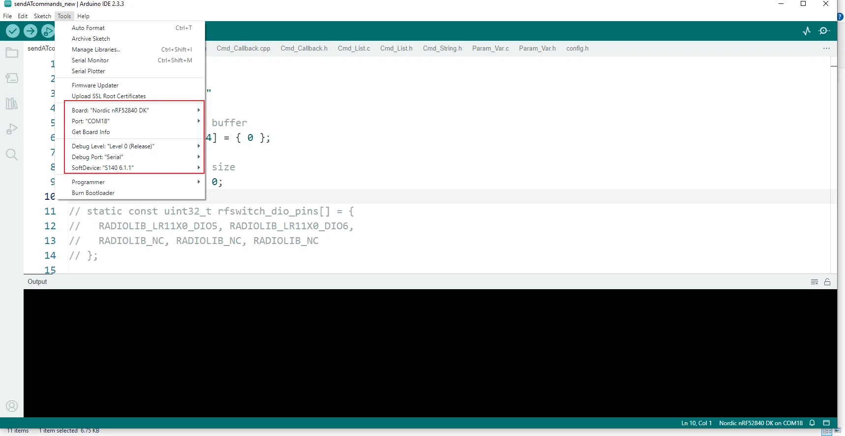
Open the code of this lesson with Arduino and select the corresponding development board configuration.
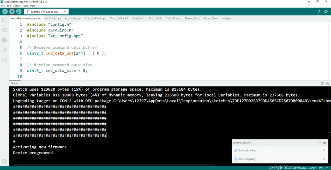
Click "Burn" in Arduino. Wait for the burn to finish, and then the nRFLRCC68 Node Board can be configured for USB-TTL communication.
Note: After the program is burned, power off the nRFLRCC68 Node Board, and then power it on again!
-
Use the SSCOM serial port tool to send AT commands to configure the nRFLRCC68 Node Board as the OTAA node application created on TTN. Then, send AT commands to make the nRFLRCC68 Node Board join the LoRaWAN network, complete the network communication with the gateway, and upload the real - time communication data between the node and the gateway to the TTN server.
-
Join the LoRaWAN network using the OTAA mode (the default network access method of the nRFLRCC68 Node Board).
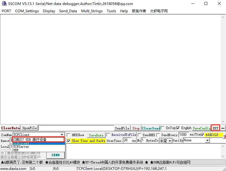
STEP1:Open the SSCOM serial port tool in the serial port assistant. Select the USB COM port recognized by the computer and click "EXT", as shown in the figure below:
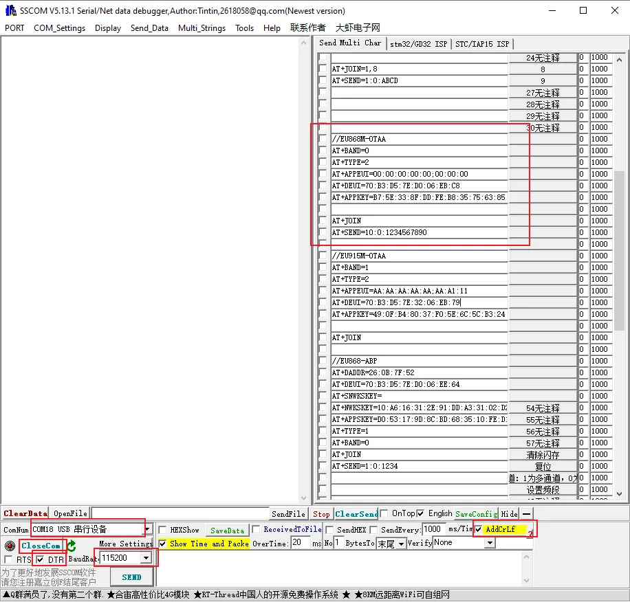
STEP2:Make the following selections and input AT command information on the extended interface of the serial port assistant:
(1)Serial port Settings
-
Baud rate:115200
-
Check the option for adding carriage return and line feed in the serial port.
-
Open the serial port and select "Data Terminal Ready": Click "opencom" and only check the "DTR" option.
(2)Configuration steps for the node to access the single-channel gateway (send AT commands)
-
Set the network access frequency band of the node: AT+BAND=0. (0 represents the 868 MHz frequency band, 1 represents the 915 MHz frequency band. The node has been configured in the eight-channel mode.)
-
Set the mode for the node to join the gateway:AT+TYPE=2(Set the network joining mode of the node to OTAA mode).
-
Set the node's DevEui: AT+DEUI=70:B3:D5:7E:D0:06:**** (The red part corresponds to that on the TTN server).
-
Set the node's AppEui: AT+APPEUI=AA:AA:AA:AA:AA:AA:**** (The red part corresponds to that on the TTN server).
-
Set the node's AppKey : AT+APPKEY=49:0F:B4:80:37:F0:5E:6C:5C:B3:24:F5:B5:78:**** (The red part corresponds to that on the TTN server).
Here, you need to replace the DevEui, AppEui, and AppKey with those in the created OTAA node application.
-
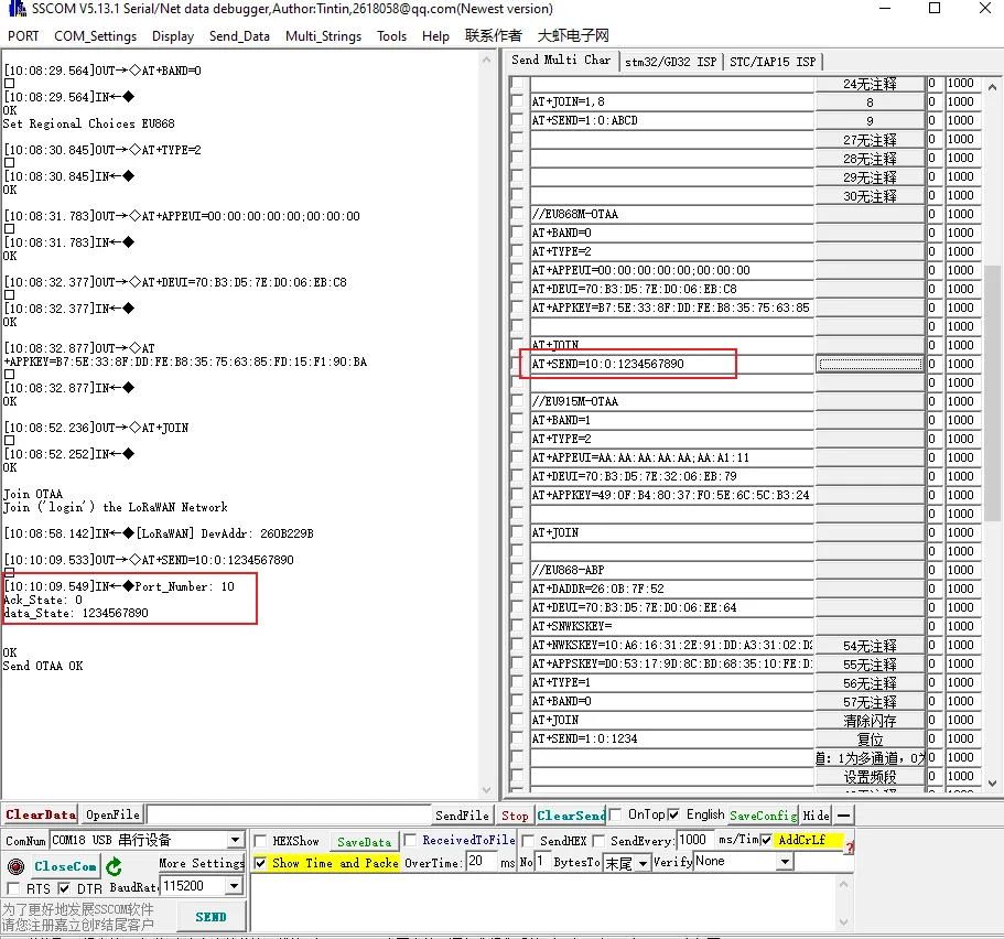
Set the node to start joining the network: AT+JOIN. After sending this command, you need to wait for the node to join the network. Only after the node successfully joins the network can you send the next command, as shown in the following figure: After the node successfully joins the network, the information printed by the serial port tool:
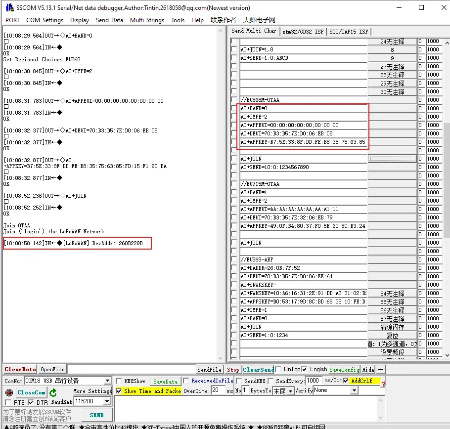
Enter the above AT commands in sequence on the extended interface of the serial port assistant. When you enter the "AT+JOIN" command, if "JoinAccept" appears, it indicates that the nRFLRCC68 node module has successfully joined the network!
-
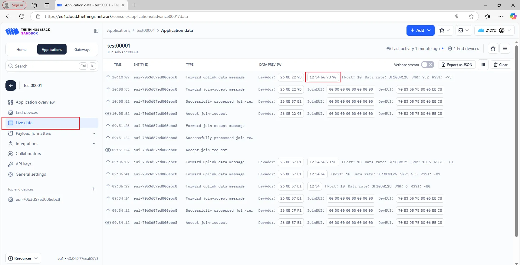
Start sending data: AT+SEND=10:0:1234567890(Parameter description: The last parameter is the data to be sent, and only an even number of data can be sent).
The commands in the SSCOM serial port tool are as follows:
-
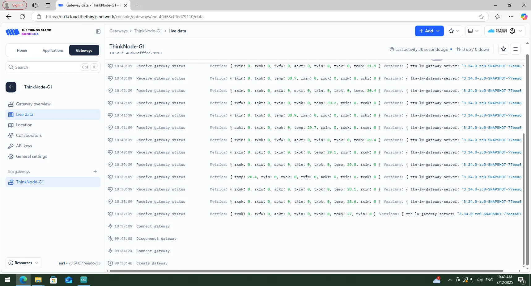
After sending data using the "AT+SEND=10:0:1234567890" command, you can view the data "1234567890" sent by the node in real - time in the "Applications -> Live data" section of the TTN server background.