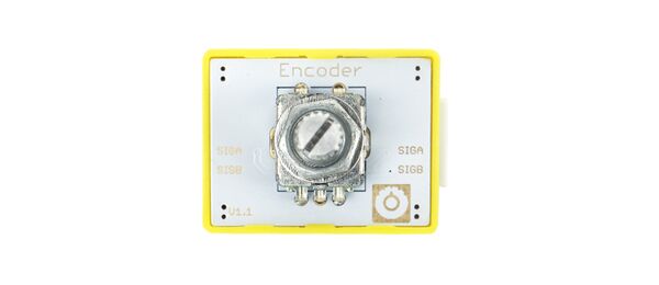
Crowbits-Encoder
Description
The rotary encoder can convert the angular displacement and linear Displacement to the electrical signal, and then convert the electrical signal to the electrical pulse. The numbers of the pulse can be converted to the value of the angular displacement. There are two output pins of this module including signal A and signal B. We can determine the position of the detent and the direction of the rotation by sense the value of the output pins.
Features
- Incremental encoder
- Easy to use
Specification
- Operating Voltage: 3.3V DC
- Dimensions: 31.5(L)*24.5(W)*13(H)mm
Usage
The following sketch demonstrates a simple application of the module. 1.You need to prepare a Crowbits motherboard, such as Crowbits-UNO board. 2.Connect the module to the D2 and D3 interface of the Crowbits-UNO board, as shown in the figure: 3.Upload the following code to the Crowbits-UNO board.
#define ENCODER_A_PIN 2
#define ENCODER_B_PIN 3
long position;

void setup(){

  pinMode(ENCODER_A_PIN, INPUT);
  pinMode(ENCODER_B_PIN, INPUT);
  attachInterrupt(0, read_quadrature, CHANGE);
  Serial.begin(9600);
}

void loop(){
   Serial.print("Position: ");
   Serial.println(position, DEC);
   delay(1000);
}

void read_quadrature(){

  if (digitalRead(ENCODER_A_PIN) == LOW){
    //Check clockwise or counterclockwise
    if (digitalRead(ENCODER_B_PIN) == LOW)
      position++;
  }

  else{
    if (digitalRead(ENCODER_B_PIN) == LOW)
      position--;
  }
}
4. After the upload is successful, open the serial port monitor, the baud rate is set to 9600. Rotate the encoder, the serial port will print out the position information, as shown in the figure:
