Elecrow ESPduino UNO+ESP8266 Wifi Board
Description
The Elecrow ESPduino combines a Arduino UNO with a serial WiFi and can be apply on lots of project of IOT, such as Smart Home, Smart robot, Security system. The same size with more powerful function, this two in one board will give you surprise!
Same as the Arduino UNO, the ESPduino also has 14 digital input/output pins (of which 6 can be used as PWM outputs), 6 analog inputs, a 16 MHz ceramic resonator, a USB connection, a power jack, an ICSP header, a reset button, and of course a Mini USB cable, simply connect it to a computer with a USB cable or power it with a AC-to-DC adapter or battery to get started.
Model: ACM82664A
Summary
| Microcontroller | ATmega328 |
|---|---|
| Operating Voltage | 5v |
| Input Voltage (recommended) | 7-12V |
| Input Voltage (limits) | 6-15V |
| Digital I/O Pins | 14 (of which 6PINs provide PWM output) |
| Analog Input Pins | 8 |
| DC Current per I/O Pin | 40mA |
| DC Current for 3.3V Pin | 50 mA |
| Flash Memory | 32 KB (ATmega328) of which 0.5 KB used by bootloader |
| SRAM | 2 KB (ATmega328) |
| EEPROM | 1 KB (ATmega328) |
| Clock Speed | 16 MHz |
Features
- Connection Mode:U(UART)
- One high speed serial port
- Working voltage:5v
- 802.11 b/g/n protocol
- Wi-Fi Direct (P2P), soft-AP
- Integrated TCP/IP protocol stack
- Integrated TR switch, balun, LNA, power amplifier and matching network
- Integrated PLL, regulators, and power management units
- +19.5dBm output power in 802.11b mode
- Dimensions(mm):70.0(L)x55.0(W)x11.8(H)
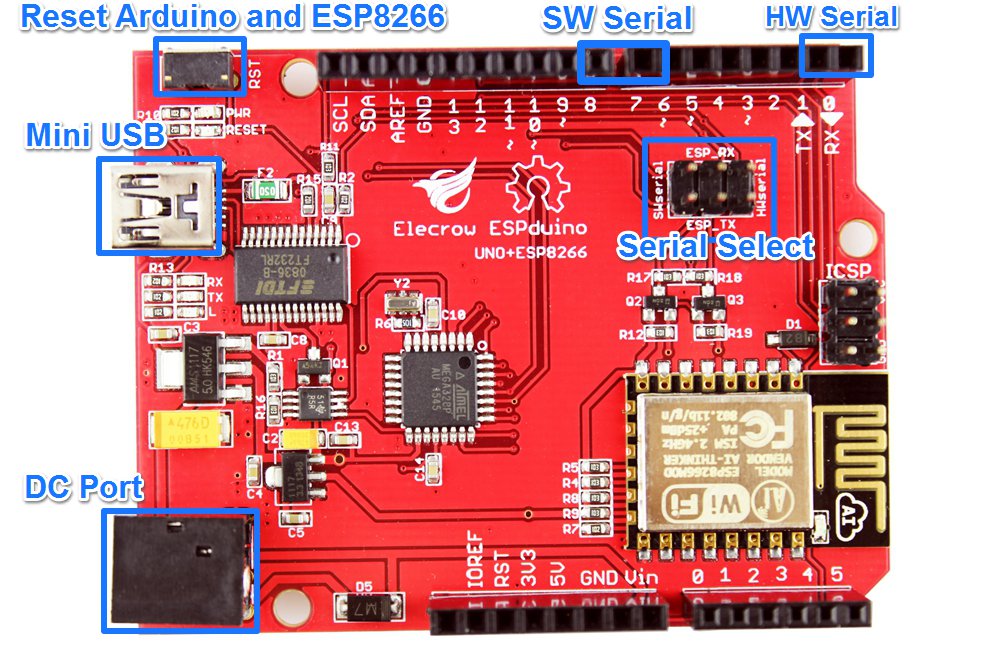
Interface Function
AT Commands
Format
- Baud rate at 115200
- x is the commands
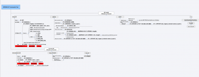
(Click the picture to zoom in)
| Set | Inquiry | Test | Execute |
|---|---|---|---|
| AT+<x>=<…> | AT+<x>? | AT+<x>=? | AT+<x> |
| AT+CWMODE=<mode> | AT+CWMODE? | AT+CWMODE=? | - |
| Set the network mode | Check current mode | Return which modes supported | - |
Commands
- carefully there are must be no any spaces between the " and IP address or port
| Commands | Description | Type | Set/Execute | Inquiry | test | Parameters and Examples |
|---|---|---|---|---|---|---|
| AT | general test | basic | - | - | - | - |
| AT+RST | restart the module | basic | - | - | - | - |
| AT+GMR | check firmware version | basic | - | - | - | - |
| AT+CWMODE | wifi mode | wifi | AT+CWMODE=<mode> | AT+CWMODE? | AT+CWMODE=? | 1= Sta, 2= AP, 3=both, Sta is the default mode of router, AP is a normal mode for devices |
| AT+CWJAP | join the AP | wifi | AT+ CWJAP =<ssid>,< pwd > | AT+ CWJAP? | - | ssid = ssid, pwd = wifi password |
| AT+CWLAP | list the AP | wifi | AT+CWLAP | |||
| AT+CWQAP | quit the AP | wifi | AT+CWQAP | - | AT+CWQAP=? | |
| AT+ CWSAP | set the parameters of AP | wifi | AT+ CWSAP= <ssid>,<pwd>,<chl>, <ecn> | AT+ CWSAP? | ssid, pwd, chl = channel, ecn = encryption; eg. Connect to your router: AT+CWJAP="www.electrodragon.com","helloworld"; and check if connected: AT+CWJAP? | |
| AT+CWLIF | check join devices' IP | wifi | AT+CWLIF | - | - | |
| AT+ CIPSTATUS | get the connection status | TCP/IP | AT+ CIPSTATUS | <id>,<type>,<addr>,<port>,<tetype>= client or server mode | ||
| AT+CIPSTART | set up TCP or UDP connection | TCP/IP | 1)single connection (+CIPMUX=0) AT+CIPSTART= <type>,<addr>,<port>; 2) multiple connection (+CIPMUX=1) AT+CIPSTART= <id><type>,<addr>, <port> | - | AT+CIPSTART=? | id = 0-4, type = TCP/UDP, addr = IP address, port= port; eg. Connect to another TCP server, set multiple connection first: AT+CIPMUX=1; connect: AT+CIPSTART=4,"TCP","X1.X2.X3.X4",9999 |
| AT+CIPMODE | set data transmission mode | TCP/IP | AT+CIPMODE=<mode> | AT+CIPSEND? | 0 not data mode, 1 data mode; return "Link is builded" | |
| AT+CIPSEND | send data | TCP/IP | 1)single connection(+CIPMUX=0) AT+CIPSEND=<length>; 2) multiple connection (+CIPMUX=1) AT+CIPSEND= <id>,<length> | AT+CIPSEND=? | eg. send data: AT+CIPSEND=4,15 and then enter the data. | |
| AT+CIPCLOSE | close TCP or UDP connection | TCP/IP | AT+CIPCLOSE=<id> or AT+CIPCLOSE | AT+CIPCLOSE=? | ||
| AT+CIFSR | Get IP address | TCP/IP | AT+CIFSR | AT+ CIFSR=? | ||
| AT+ CIPMUX | set mutiple connection | TCP/IP | AT+ CIPMUX=<mode> | AT+ CIPMUX? | 0 for single connection 1 for multiple connection | |
| AT+ CIPSERVER | set as server | TCP/IP | AT+ CIPSERVER= <mode>[,<port> ] | mode 0 to close server mode, mode 1 to open; port = port; eg. turn on as a TCP server: AT+CIPSERVER=1,8888, check the self server IP address: AT+CIFSR=? | ||
| AT+ CIPSTO | Set the server timeout | AT+CIPSTO=<time> | AT+CIPSTO? | <time>0~28800 in second | ||
| +IPD | received data | For Single Connection mode(CIPMUX=0): + IPD, <len>: For Multi Connection mode(CIPMUX=1): + IPD, <id>, <len>: <data> |
Usage
Change the baud rate
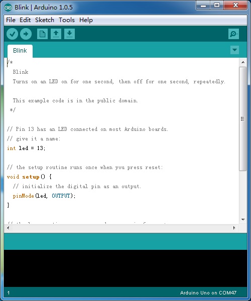
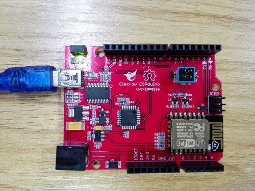
The default baud rate of ESP8266-12E was 115200 bps, if communication with UNO software serial, it may make some mistake, we need to change it low than 19200bps. 1.upload a blink code to the ESPduino, as below:
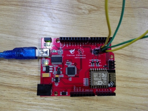
2.we use the hardware serial[FT232] sent the AT Command to ESP8266.Connect ESP_RX TO TX and ESP_TX TO RX. Show as below:
3.Open a Serial debug tool, i use the SSCOM3.2. As below: 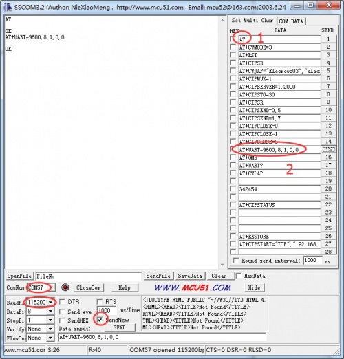
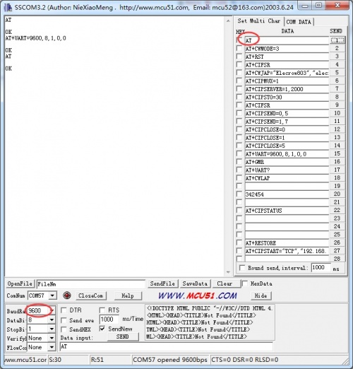
4.Change the baud of the SSCOM3.2, and sent a AT to the ESP8266, test it whether change the baud rate succeed.
Use the ESPduino as a Webserver
1.Hardware Connection.
Connected the ESP8266 to the software serial( D7 and D8) by the jumper cap.As below:
By the way, before you do that,you need to change the ESP8266 baud rate to 9600.
2.Connect the board to PC using USB cable.
3:Download the code: Webserver_for_ESP8266 or copy it to you new skecth.
#include <SoftwareSerial.h>

#define DEBUG true

SoftwareSerial esp8266(7,8); // make RX Arduino line is pin 7, make TX Arduino line is pin 8.
                             // This means that you need to connect the TX line from the esp to the Arduino's pin 7
                             // and the RX line from the esp to the Arduino's pin 8
void setup()
{
  Serial.begin(9600);
  esp8266.begin(9600); // your esp's baud rate might be different
  sendData("AT+RST\r\n",2000,DEBUG); // reset module
  sendData("AT+CWMODE=2\r\n",1000,DEBUG); // configure as access point
  sendData("AT+CIFSR\r\n",1000,DEBUG); // get ip address
  sendData("AT+CIPMUX=1\r\n",1000,DEBUG); // configure for multiple connections
  sendData("AT+CIPSERVER=1,80\r\n",1000,DEBUG); // turn on server on port 80
}

void loop()
{
  if(esp8266.available()) // check if the esp is sending a message
  {
    /*
    while(esp8266.available())
    {
      // The esp has data so display its output to the serial window
      char c = esp8266.read(); // read the next character.
      Serial.write(c);
    } */

    if(esp8266.find("+IPD,"))
    {
     delay(1000);

     int connectionId = esp8266.read()-48; // subtract 48 because the read() function returns
                                           // the ASCII decimal value and 0 (the first decimal number) starts at 48

     String webpage = "<h1>Hello World!</h1>";
     String cipSend = "AT+CIPSEND=";
     cipSend += connectionId;
     cipSend += ",";
     cipSend +=webpage.length();
     cipSend +="\r\n";

     sendData(cipSend,1000,DEBUG);
     sendData(webpage,1000,DEBUG);

     String closeCommand = "AT+CIPCLOSE=";
     closeCommand+=5; // append connection id
     closeCommand+="\r\n";
     sendData(closeCommand,3000,DEBUG);
    }
  }
}


String sendData(String command, const int timeout, boolean debug)
{
    String response = "";

    esp8266.print(command); // send the read character to the esp8266

    long int time = millis();

    while( (time+timeout) > millis())
    {
      while(esp8266.available())
      {
        // The esp has data so display its output to the serial window
        char c = esp8266.read(); // read the next character.
        response+=c;
      }
    }

    if(debug)
    {
      Serial.print(response);
    }
    return response;
}
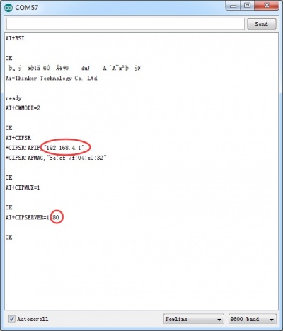
4.Upload the code and Open the serial monitor.You can see some configuration information.
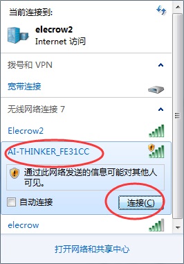
5.PC connect to the wifi of ESP8266.
6.Then you can visit the Webserver of the ESP8266.

Resources
Support
If you have any problem about how to use it, you can connect to us at the bottom-right of bazzer or contact to techsupport@elecrow.com to get technology support.