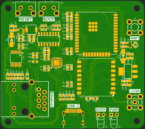
Lora Basic Gateway Module
Description
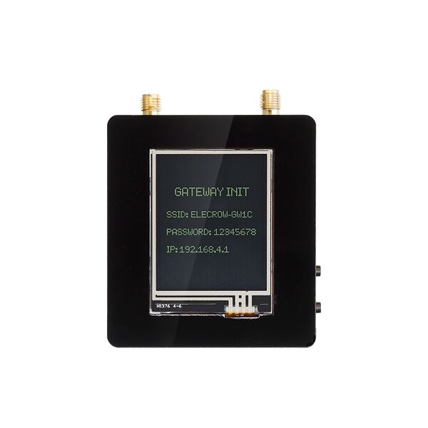
The Lora Basic Gateway Module is a single-channel Lora gateway module that combines the ESP32 WROOM 32UE with the RA-01H module. It uses a TYPE C USB interface for power supply and is equipped with a LAN8720A-10/100Mbps RMII interface Ethernet chip. In addition to being able to connect to the network via ESP32 WIFI, it can also be connected to a wired network through an RJ45 network interface. The WIFI and LORA antenna interfaces use a built-in SMA interface antenna, which supports long-distance LORA communication. The module also features a 1.8-inch touch display screen that can display gateway networking information, IP addresses, etc. The Gateway Module can be used with LORA node modules and LORA development boards to build LORA WAN IoT networks, and can be applied in fields such as smart homes, industrial and agricultural control, and more.
Model: CRT01262M
Feature
- Integrated ESP32 WROOM UE and RA-01H modules
- Main control ESP32-DOWD-V3/ESP32-DOWDR2-V3, with built-in 520KB SRAM and 4MB Flash
- Xtensa dual-core 32-bit LX6 microprocessor @ 240MHz
- ESP32 WROOM UE supports 802.11b/g/n Wifi protocol
- RA-01H module supports FSK, GFSK, MSK, LoRa and other modulation methods
- RA-01H module supports frequency band: 803MHZ-930MHZ
- Supports 10/100Mbps RJ45 interface Ethernet connection
- Compatible with Arduino/Micropython programming platform
- Supports 5V-USB power supply
- External SMA 2.4G wifi antenna, 868MHZ/915MHZ LoRa antenna
Technical Specification
- TYPE C USB input voltage: DC-5V
- Operating temperature range: -10°C ~ 65°C
- Size: 65mm (L) x 58mm (W)
Interface Function
| Name | Interface/Function Definition |
|---|---|
| PWR | Red power indicator light, always on when powered on, and off when power is off. |
| DATA | Blue data indicator light, flashes during data transmission and is off by default. |
| RESET | Reset button. Press this button to reset the system. |
| BOOT | Download button. Pressing and holding the Boot button and then pressing the RESET button can start the firmware download mode. Users can download firmware through the USB interface. |
| USB-C | USB-C interface, which is used as a power supply for the gateway module and a communication interface between the PC and ESP32. |
| WIFI | ESP32 2.4G WIFI antenna SMA interface. |
| LORA | 868MHZ/915MHZ LoRa antenna SMA interface. |
| Ethernet | 100Mbps Ethernet RJ45 interface. |
The corresponding IO ports are as shown in the figure: 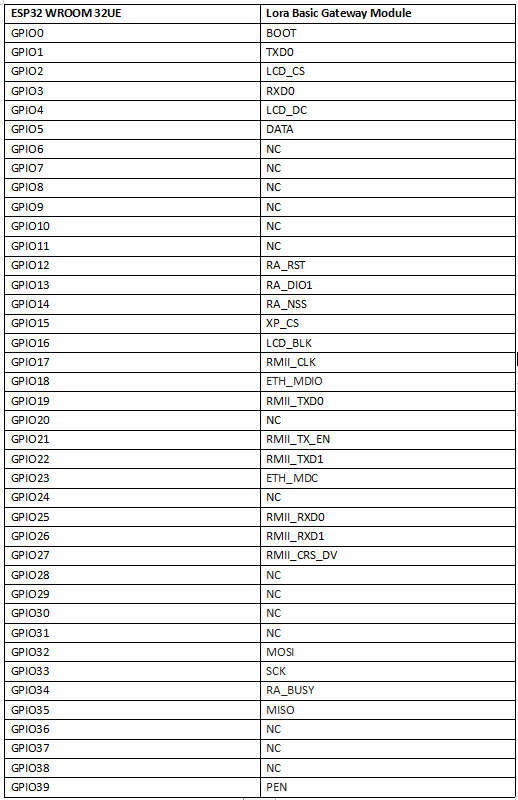
Usage
Development Environment Construction
1. Directly visit the Arduino official website and download the Arduino development tools supported by the device. The link is as follows: https://www.arduino.cc/en/software.
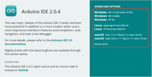
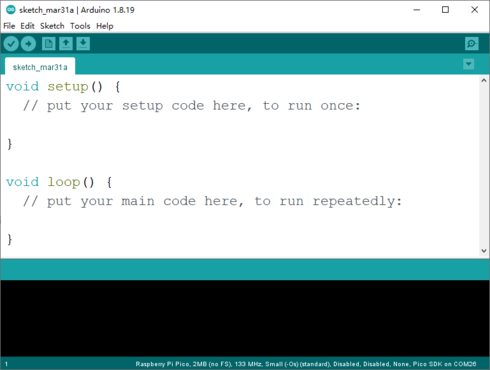
2. Click the downloaded Arduino development tool to install the software. After the software installation is complete, open it directly, as shown in the figure below:
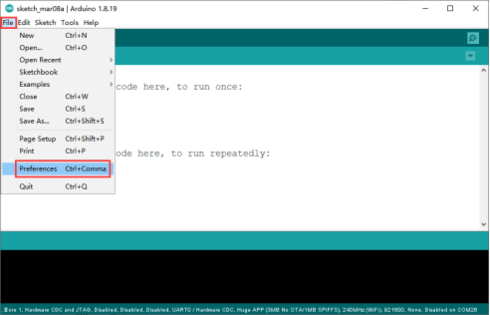
3. Click "File" -> "Preferences" on the menu bar to pop up the preference setting interface.
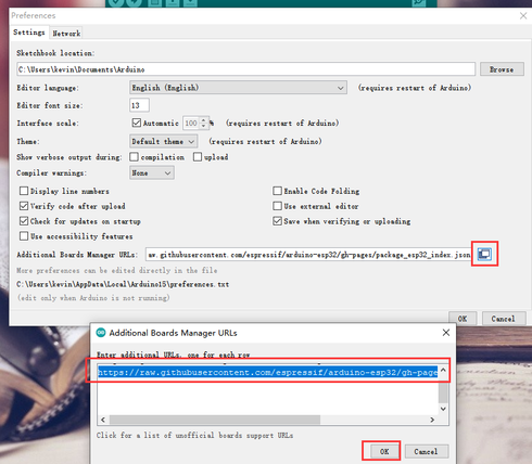
4. Click the icon on the far right of the Additional Boards Manager URLs column, enter https://raw.githubusercontent.com/espressif/arduino-esp32/gh-pages/package_esp32_index.json and https://github.com/earlephilhower/arduino-pico/releases/download/global/package_rp2040_index.json in the pop-up window.(The two URLs need to be separated by line breaks)
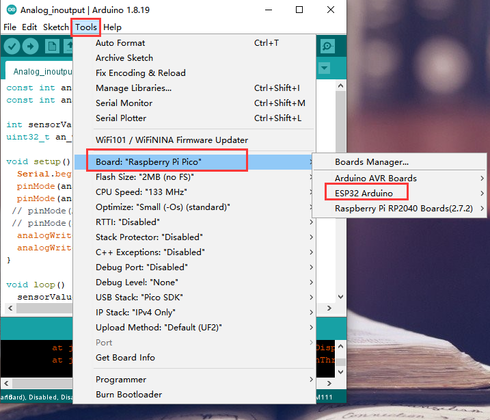
5. Click "Tools" -> "Board:..." -> "Boards Manager..." in the menu bar to enter the Boards Manager interface.
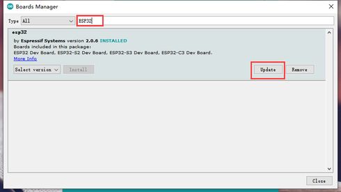
6. Enter "ESP32" in the search box, select "ESP32" and install the development environment.
It should be noted here that when selecting the development environment version, do not choose the latest one. It is recommended to choose version 2.0.3.
7. After the environment is successfully installed, if you find "ESP32 Arduino" in the Arduino IDE development board management, it means that the environment is successfully built.
Software Settings
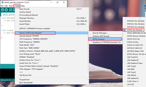
1. For the first use, you need to set up and select the correct development board. Click "Tools" -> "Board:..." -> "ESP32 Arduino" -> "ESP32 Dev Module" in the menu bar, as shown in the figure below:
2. After connecting the Lora Basic Gateway Module to the computer via a TYPE-C USB cable, the computer will automatically recognize the USB COM port (if the USB is not recognized successfully, please check if the CH340 driver has been installed on the computer).

3.After the USB COM port is successfully recognized, open the Arduino IDE and burn an example code as shown in the figure below:File->Examples->Basics->Blink
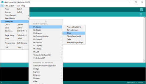
The code that is opened is as follows: modify "LED_BUILTIN" to "5".
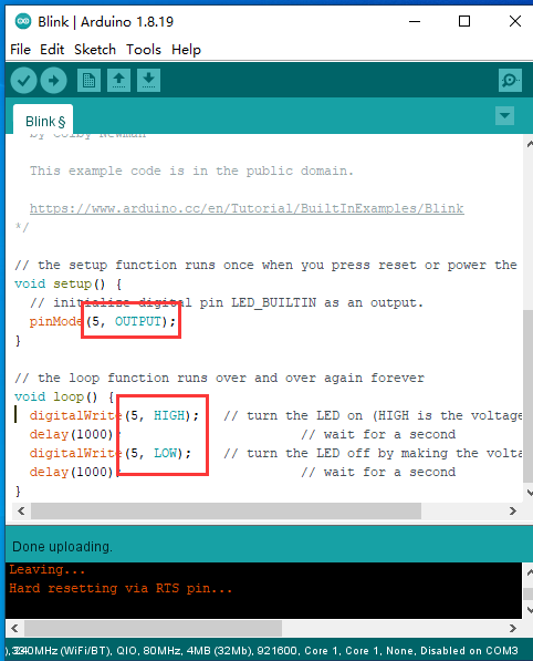
Select the recognized "COMxx port" in the Arduino IDE.
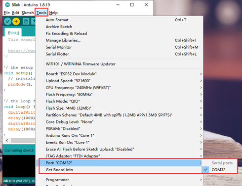
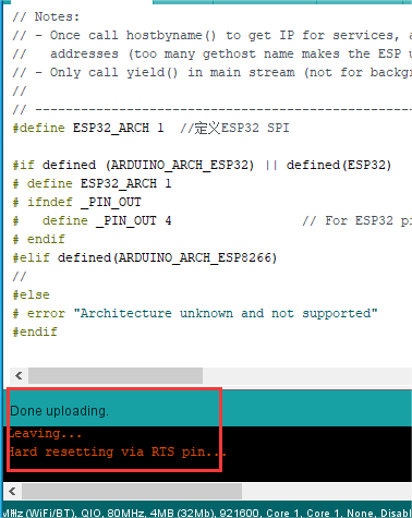
Press and hold the "BOOT" button on the Lora Basic Gateway Module, then press the "RESET" button, release the "RESET" button first, and finally release the "BOOT" button. Click "Download" to successfully burn the code into the ESP32!
Sample Program
Example: The Lora RA-08H Node Board (915MHz) uploads data to TTN server via Lora Basic Gateway Module.
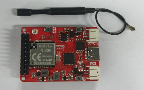
(Lora RA-08H Node Board(915MHZ)Node module)
1 Burn the example program to the Lora Basic Gateway Module via Arduino IDE.
1.1 First, copy the library files in the "libraries" folder of the "Code" folder to the Arduino IDE library management folder, as shown in the following picture..

1.2Open the "ESP-sc-gway-end.ino" file in the "ESP-Lora_Factory_program" folder.
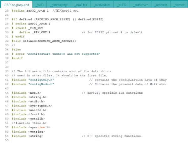
1.3 Burn the "ESP-sc-gway-end.ino" example program to the Lora Basic Gateway Module. Select the board model and COM port.
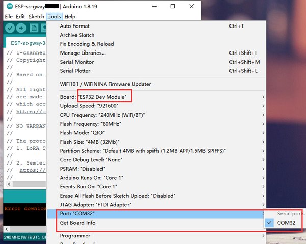
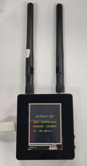
After the burning process is complete, press the RESET button to reset the module. After resetting, the LCD screen on the back of the gateway module will display the gateway configuration information, as shown in the following figure:
2 Lora Basic Gateway Module network configuration
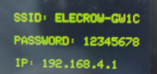
2.1 Use a mobile phone or laptop to connect to the gateway module's WiFi "ELECROW-GW1C" with the password "12345678".
2.2 Enter the webpage by typing 192.168.4.1 in the browser; configure the gateway network connection mode as WIFI (must enter the correct WIFI account password) or NET (directly connect to the router using an RJ45 cable, no WIFI information is required under NET); press Gateway Default to obtain the default gateway ID or enter a 16-digit ID of your own; enter the server address port; REGION sets the gateway working frequency band (EU868 and US915); set the gateway channel (CHANNEL) and spreading factor (SF); as shown in the figure below:
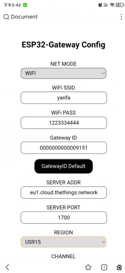
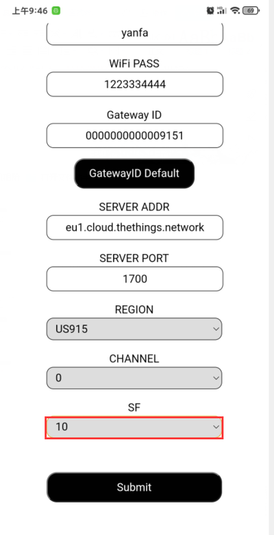
(1)NET MODE: WIFI/NET optional
(2)WIFI SSID: Fill in the name of the WiFi to be connected (no need to fill in any information under NET mode)
(3)WIFI PASS: Fill in the password of the WiFi to be connected (no need to fill in any information under NET mode)
(4)Gateway ID: Press Gateway Default to obtain the default gateway ID or enter a 16-digit ID of your own
(5)SERVER ADDR: eu1.cloud.thethings.network
(6)SERVER PORT: Default 1700
(7)REGION: The gateway working frequency band setting can choose EU868/US915
(8)CHANNEL: Default 0
(9)SF: Default 7 (Choose 7 for EU868MHz band and 10 for US915 band)
2.3After confirming that there are no errors, click Submit to submit the configuration information. The gateway will load the corresponding configuration after completion, as shown in the figure below:

3 Create a gateway in the TTN (thethings.network) server
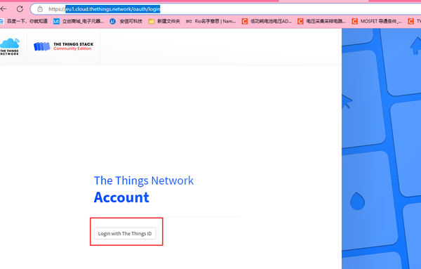
3.1 Enter eu1.cloud.thethings.network/oauth/login in the browser to enter the following web page, and click "Login with the things ID".
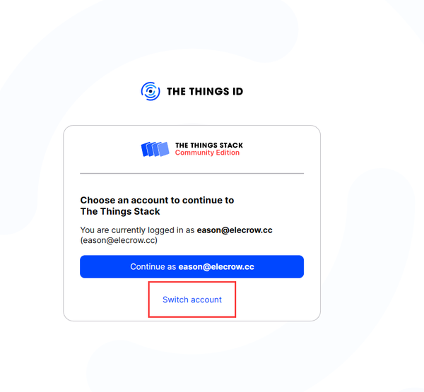
3.2 Click "Switch account" to create an account and log in (only an email account is required to register, follow the prompts to complete the registration, which will not be repeated here).
3.3 After logging in to the account, enter the following interface, and click Go to the Console.

3.4 Create a gateway in the TTN server backend by clicking Gateway->Register Gateway. Enter the following interface, and enter 16-bit ID: 0000000000009151 in the Gateway Eui (you can set the ID yourself. If the creation fails, it may be because the entered ID has been registered, so please modify the ID address).
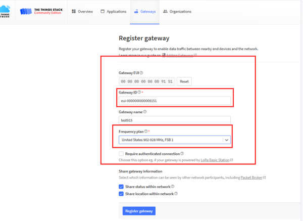
Important Note: Select the frequency band "Europe 863-870MHz (SF12 for RX2)" (choose this for LoRa nodes using 868MHz band) or "United States 902-928MHz FSB1" (choose this for testing LoRa nodes using 915MHz band).
After setting the gateway information, click "Register Gateway" to register the gateway!
After setting as shown in the figure above, register the gateway! (Make sure that the gateway ID is consistent, otherwise the connection will fail.) Click Gateway to refresh and you can see that the gateway has connected to the TTN server backend. After the gateway is established, power off and reset the gateway module, and then log in to the TTN server again to see that the gateway has connected to the TTN server (may require multiple repetitions).

4 Add the node application of the Lora RA-08H Node Board (915MHz) to the TTN server
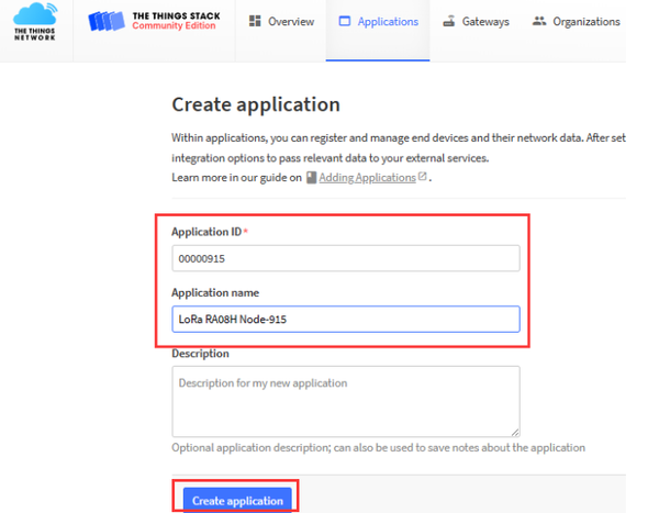
4.1 Click Applications->Create Applications and enter the Applications ID and Applications name in the pop-up interface. After entering, click "Create Applications".

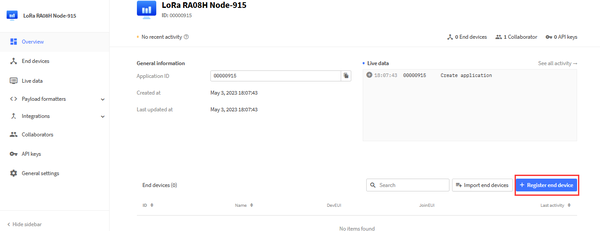
Click Register end device to register the node.
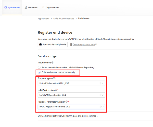
Enter the following interface, and set it as shown in the figure below (Frequency plan is optional):
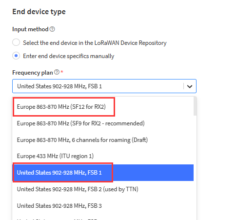
If you are using a 868MHz gateway, select "Europe 863-870MHz (SF12 for RX2)"
If you are using a 915MHz gateway, select "United States 902-928MHz FSB1"
4.2 Configure the DevEui, AppEui, and AppKey information of the RA-08H node module as shown in the figure below:
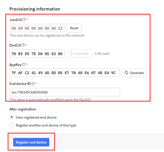
Click Register end device to register the device. After successful registration, enter the following interface:
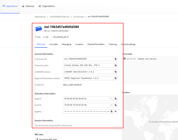
5. The Lora RA-08H Node Board (915MHz) node module connects to the TTN gateway server and uploads data by configuring AT commands.
5.1. First, burn the serial application program to the Lora RA-08H Node Board (915MHz) node module. In the Code folder, open the "RA-08_H.ino" program using the Arduino IDE.
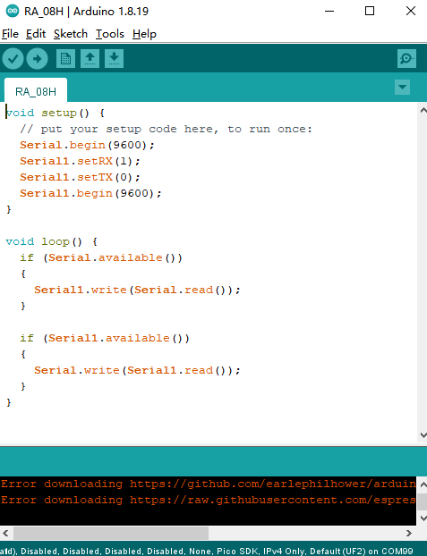
Select the board type, COM port, and burn it!

5.2. After the program is successfully burned, use the serial assistant tool in the TOOL folder to send AT commands to configure the Lora RA-08H Node Board (915MHz) node module as shown below:
(1) Serial port settings
(2) Node access to single channel gateway configuration steps (Send AT commands)
1. Set the node access method to OTAA: AT+CJOINMODE=0
2. Set the node group frequency mask: AT+CFREQBANDMASK=0001 (Set channels 0-7)
3. Set the node type: AT+CLASS=0 (Class A node)
4. Set the node DevEui: AT+CDEVEUI=70B3D57ED005D380 (The red part corresponds to the TTN server)
5. Set the node AppEui: AT+CAPPEUI=0000000000000022 (The red part corresponds to the TTN server)
6. Set the node AppKey: AT+CAPPKEY=7FAFC241494DDD85E77840E60748E49C (The red part corresponds to the TTN server)
7. Set the node to turn off adaptive spreading factor: AT+CADR=0
8. Set the uplink communication rate after the node successfully joins: AT+CDATARATE=5 (Values 0-5, depending on the gateway configuration for 868 and 915, different frequency bands have different settings. See the protocol macro definition below. AT+CDATARATE=5 corresponds to 868, and AT+CDATARATE=0 corresponds to 915.)
9. Set the receive window delay: AT+CRX1DELAY=1 (Default=1 for 1 second, increase the time based on distance and network status to improve the success rate of join, generally no need to change)
10. Set the port for the node to receive TTN downlink data: AT+CAPPPORT=2 (The red part corresponds to the TTN server)
11. Set the node uplink and downlink on the same frequency: AT+CULDLMODE=1 (1 for same frequency, 2 for different frequency)
12. Set the node to join the network: AT+CJOIN=1,0,8,8 (Appear +CJOIN:OK for success)
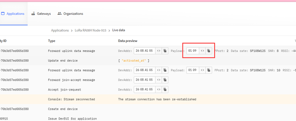
13. Set the node to send data to the TTN server: AT+DTRX=0,10,2,0109 (Can be sent after successful joining, data format must be even)
Click on EXT and enter the following AT commands in the serial tool's extension column, making sure to enter the DevEui, AppEui, and AppKey corresponding to the node in TTN.
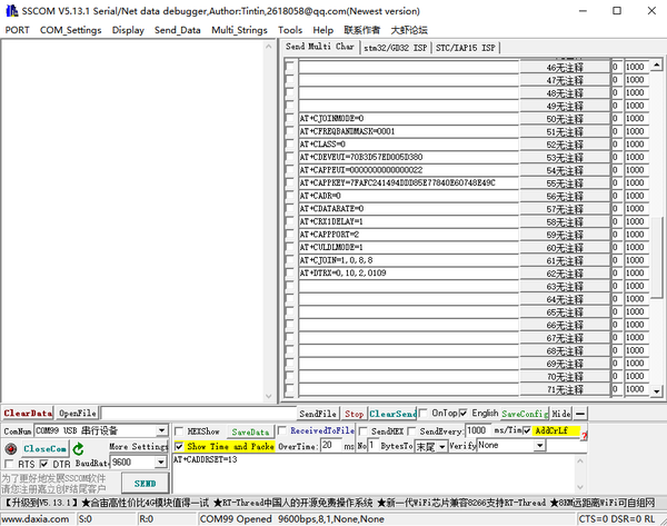

Send the command "AT+CJOIN=1,0,8,8" and wait until the serial port prints "Successfully joined!" to confirm successful joining.

Send the command "AT+DTRX=0,10,2,0109" and then send the data "0109". The Lora RA-08H Node Board (915MHz) node module will successfully upload the data "0109" to the TTN server!

Resource
- Lora_Gateway_Module
- Lora_GateWay_Datasheet
- Lora_GateWay_Eagle_File
- Lora_GateWay_Tool
- Lora_gateway_Libraries.rar
- ESP-Lora_Factory_program.rar
Github link:

