LR1302 LoRaWAN Gateway Module
Description
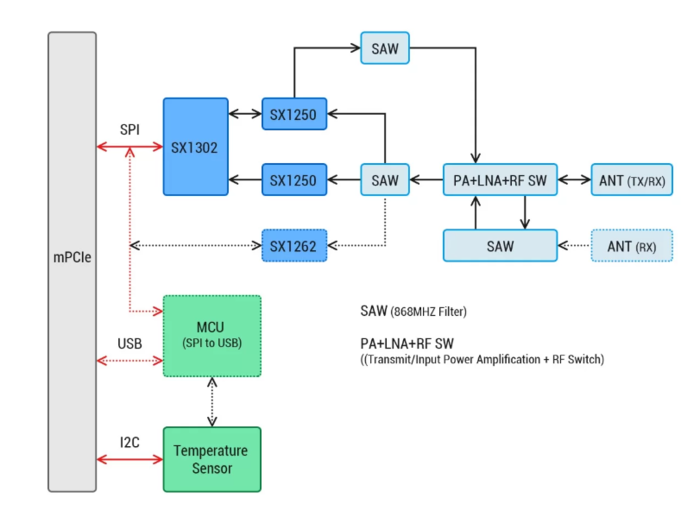
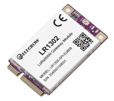
This LR1302 module is a new generation LoRaWAN® gateway module. It adopts a mini-PCIe form factor design and features low power consumption and high performance. Based on Semtech Network's SX1302 LoRaWAN® baseband chip, the LR1302 gateway module provides gateway products with potential capacity for long-distance wireless transmission. Compared to the previous SX1301 and SX1308 LoRa chips, the SX1302 chip has higher sensitivity, lower power consumption and lower operating temperature. It supports 8-channel data transmission, improves communication efficiency and capacity, and supports the connection and data transmission of more devices.
It reserves two antenna interfaces, one for transmitting and receiving LoRa signals and one U.FL (IPEX) interface for independent transmission. It also has a metal shield to protect against external interference and provide a reliable communications environment.
The LR1302 LoRaWAN® gateway module is available in SPI and USB versions, covering the US915 and EU868 frequency bands, giving you a choice of LoRaWAN® frequency solutions.
Designed specifically for the IoT space, the LR1302 is suitable for a variety of IoT applications. Whether used in smart cities, agriculture, industrial automation or other fields, the LR1302 module can provide reliable connections and efficient data transmission.
Model: CRT01266M001
Feature
- Uses Semtech® SX1302 baseband LoRa® chip with extremely low power consumptionand excellent performance;
- Mini-PCIe form factor and compact design make it easier to integrateinto various gateway devices, suitable for space-constrained application scenarios, and provide flexible deployment options;
- Support 8-channeldata transmission, provide more efficient communication efficiency and capacity;
- Ultra-low operating temperatureeliminates the need for additional cooling and reduces the size of the LoRaWAN® gateway;
- Uses SX1250 TX/RX front end with sensitivity down to -139 dBm@SF12; TX power up to 26 dBm @3.3V;
- With CE and FCC certification, simplify the certification process of the final product and provide convenience for certification.
Hardware Overview
Technical Specification
| Region | EU868 | US915 |
|---|---|---|
| Frequency | 863-870MHz | 902-928MHz |
| Sensitivity | -125dBm 125K/SF7 -139dBm 125K/SF12 | -125dBm 125K/SF7 -139dBm 125K/SF12 |
| TX Power | 26 dBm (with 3.3V power supply) | 25 dBm (with 3.3V power supply) |
| LEDs | Power: Green Config: Red TX: Green RX: Blue | Power: Green Config: Red TX: Green RX: Blue |
| Form Factor | Mini PCIe, 52pin Golden Finger | Mini PCIe, 52pin Golden Finger |
| Power Consumption (SPI version) | Standby: 7.5 mA TX maximum power: 415 mA RX: 40 mA | Standby: 7.5 mA TX maximum power: 415 mA RX: 40 mA |
| Power Consumption (USB version) | Standby: 20 mA TX maximum power: 425 mA RX: 53 mA | Standby: 20 mA TX maximum power: 425 mA RX: 53 mA |
| LBT(Listen Before Talk) | Support | Support |
| Antenna Connector | U.FL | U.FL |
| Operating Temperature | -40°C to 85°C | -40°C to 85°C |
| Dimensions | 30 mm (width) × 50.95 mm (length) | 30 mm (width) × 50.95 mm (length) |
| Certification | CE | FCC |
Interface Function
The corresponding IO ports are as shown in the figure: 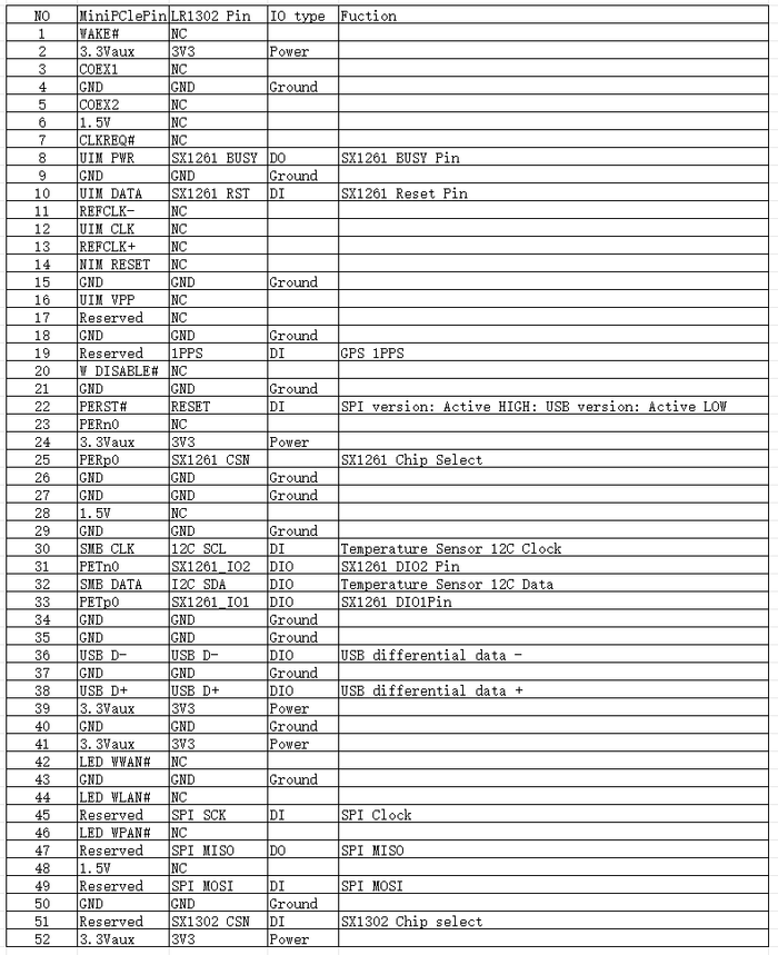
Applications
-
LPWAN Gateway Device Development.
-
Any long-range wireless communication application development.
-
LoRa® and LoRaWAN® Application Learning and Research.
Usage
Hardware Preparation
(1) LR1302 LoRaWAN® gateway module
(2) Raspberry Pi board with 40-pin GPIO connector (e.g. Raspberry Pi 4B or Raspberry 3B+)
(3) LR1302 LoRaWAN HAT for Raspberry Pi for RPI_PRD
(4) Raspberry Pi power adapter
(5) LoRa® antenna
(6) 8G or larger SD card and card reader
(7) Type C USB cable (if using the WM1302 LoRaWAN® Gateway Module USB version)
Software preparation
(1) The latest Raspberry Pi OS image: Raspberry Pi OS Lite is recommended.
(2) Balena Etcher: Refresh the Raspberry Pi OS image to SD card.
A Raspberry Pi setup steps:
Step 1 :Install LR1302 LoRaWAN HAT for RPI_PRD and install LR1302_LoRaWAN
Easily install the Hat onto the Raspberry Pi 40-pin connector. First power down the Raspberry Pi and insert the LR1302 module into the Hat as shown below and tighten it down.
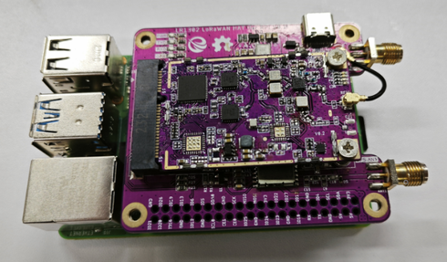
If using the USB version of the LR1302 module, also connect its Type C port to the Raspberry Pi USB port using the Type C USB cable. 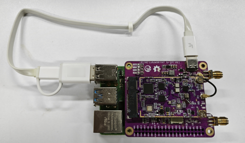
Step 2 : Enable Raspbian I2C and SPI Interfaces
The LR1302 module communicates with the Raspberry Pi via SPI and I2C. However, these two interfaces are not enabled by default in Raspbian, so developers need to enable them before using LR1302. Here, we introduce a command line way to enable the SPI and I2C interfaces. First, log in to the Raspberry Pi via SSH or using a monitor (do not use the serial console as the GPS module on the Pi Hat will take over the Pi's hardware UART pins), and then enter a command line to open the Rasberry Pi software configuration tool sudo raspi-config:
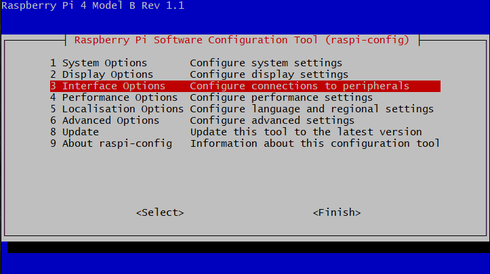
1. Select "Interface Options".
2. Select SPI, then select Yes to enable it.
3. Select I2C and select Yes to enable it.
4. Select Serial Port, then select No "Do you want to log into the shell..." and select Yes "Do you want serial port hardware...".
5. After that, please reboot the Raspberry Pi to make sure these settings are valid.
Step 3 : Getting and compiling the SX1302 source
Now let's install git from github and download sx1302_hal (the library and program for the SX1302 LoRa gateway):
sudo apt update
sudo apt install -y git
cd ~
git clone https://github.com/Elecrow-RD/LR1302_loraWAN.git

Move to the sx1302_hal folder and compile everything:

cd ~/sx1302_hal
make
Step 4 : Configure TTN-related content.
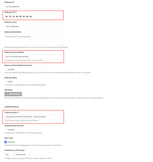
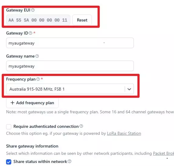
Log in to the TTNv3 console, click Go to Gateway, and then click Add Gateway on the Add Gateway page. You need to pay attention to the gateway EUI and gateway server address and the corresponding frequency, and just keep the other settings as default. (Refer to the wiki of Lora_Basic_Gateway_Module for specific steps, the part about ttn creation, Lora Basic Gateway Module) Gateway EUI: the 64-bit Extended Unique Identifier of the gateway, which is set to AA555A0000000000 in this wiki.
Gateway Server Address: the address of the server that the gateway will connect to, copy it to the clipboard, the developer will need to save it to the configuration file later on
Gateway Server Address: the address of the server that the gateway will connect to, copy it to the clipboard, the developer will need to save it to the configuration file later on
Frequency Selection: If using the EU868 module, select Europe "Europe 863-870 MHz (SF9 for RX2)", if using the US915 module, select United States "United States 902-928 MHz, FSB 2". United States 902-928 MHz, FSB 2" for US915 module.
If using the AU915 module, select United States "Australia 915-928 MHz, FSB 1". "Australia 915-928 MHz, FSB 1" for AU915 module.
After adding the gateway, go back to the Raspberry Pi and press CTRL + c to stop lora\_pkt\_fwd, then use the text editor nano to edit the global\_conf.json.sx1250.xxxx configuration file that you just used:
# Please select one of the following comands based on your module
# for WM1302 LoRaWAN Gateway Module (SPI) - EU868
nano global_conf.json.sx1250.EU868

# for WM1302 LoRaWAN Gateway Module (USB) - EU868
nano global_conf.json.sx1250.EU868.USB

# for WM1302 LoRaWAN Gateway Module (SPI) - US915
nano global_conf.json.sx1250.US915

# for WM1302 LoRaWAN Gateway Module (USB) - US915
nano global_conf.json.sx1250.US915.USB

# for WM1302 LoRaWAN Gateway Module (SPI) - AU915
nano global_conf.json.sx1250.AU915
Basically, just change these parameters: "server_address", "serv_port_up" and "serv_port_down" are located at the end of the configuration file. Copy the gateway server address to "server_address", change "serv_port_up" and "serv_port_down" to 1700 and these parameters should be edited like this:
"gateway_conf": {
"gateway_ID": "AA555A0000000000",
/* change with default server address/ports */
"server_address": "eu1.cloud.thethings.network",
"serv_port_up": 1700,
"serv_port_down": 1700,
AU915:
"gateway_conf": {
"gateway_ID": "AA555A0000000011",
/* change with default server address/ports */
"server_address": "au1.cloud.thethings.network",
"serv_port_up": 1700,
"serv_port_down": 1700,
Press CTRL + x to save these changes, then y and finally Enter to close the text editor.
Restart lora_pkt_fwd and you will see that the Raspberry Pi Gateway is connected to the TTN.
Note: Make sure you have the reset_lgw.sh file under the current path when running lora_pkt_fwd.
# Please select one of the following comands based on your module
# for WM1302 LoRaWAN Gateway Module (SPI) - EU868
./lora_pkt_fwd -c global_conf.json.sx1250.EU868

# for WM1302 LoRaWAN Gateway Module (USB) - EU868
./lora_pkt_fwd -c global_conf.json.sx1250.EU868.USB

# for WM1302 LoRaWAN Gateway Module (SPI) - US915
./lora_pkt_fwd -c global_conf.json.sx1250.US915

# for WM1302 LoRaWAN Gateway Module (USB) - US915
./lora_pkt_fwd -c global_conf.json.sx1250.US915.USB

# for WM1302 LoRaWAN Gateway Module (SPI) - AU915
./lora_pkt_fwd -c global_conf.json.sx1250.AU915
B. with RA-08H terminal lora node function debugging
Step 1. Raspberry Pi LoraWan Gateway
(1) Connect to the network (wifi or wired)
(2) Run the program
1. Open Raspberry Pi shell
2. Run the command
Note: Please make sure there is reset_lgw.sh file under current path when running lora_pkt_fwd.
868SPI mode:
sudo /home/pi/sx1302_hal/packet_forwarder/lora_pkt_fwd -c /home/pi/sx1302_hal/packet_forwarder/global_conf.json.sx1250.EU868
868USB mode:
sudo /home/pi/sx1302_hal/packet_forwarder/lora_pkt_fwd -c /home/pi/sx1302_hal/packet_forwarder/global_conf.json.sx1250.EU868.USB
915SPI mode:
Sudo  /home/pi/sx1302_hal/packet_forwarder/lora_pkt_fwd  -c /home/pi/sx1302_hal/packet_forwarder/global_conf.json.sx1250.US915.USB
915USB mode:
Sudo  /home/pi/sx1302_hal/packet_forwarder/lora_pkt_fwd  -c /home/pi/sx1302_hal/packet_forwarder/global_conf.json.sx1250.US915.USB

AU915SPI mode:
Sudo  /home/pi/sx1302_hal/packet_forwarder/lora_pkt_fwd  -c /home/pi/sx1302_hal/packet_forwarder/global_conf.json.sx1250.AU915
3. Check whether it connects to the TTN server normally and receives heartbeat packets

Step 2. RA-08H connected to the computer serial port
(1)Connecting RA-08H serial port: use SSCOM connection, baud rate 115200.

(2) Import "sscom51.ini" ini file.
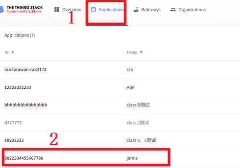
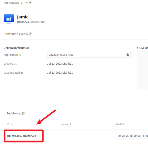
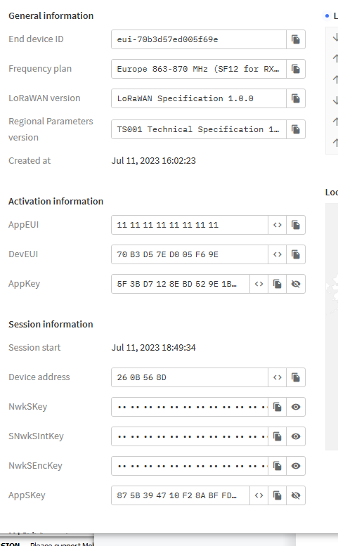
(3) OTAA network allocation: you need to modify DEVEUI according to the relevant data shown in TTN, APPEUI and APPKEY. (Here take the official TTN node as an example, users need to set up according to their own TTN node, and also configure different frequency parameters according to different modes.)
SSCOM input to the RA-08H at the computer side of the node:
1.AT+CJOINMODE=0
2.AT+CCLASS=2
3.AT+CDEVEUI=70b3d57ed005f69e
4.AT+CAPPEUI=1111111111111111
5.AT+CAPPKEY=5F3BD7128EBD529E1BB68BE55ABED395
6.AT+CFREQBANDMASK=0002
7.AT+CULDLMODE=2
8.AT+CJOIN=1,1,10,3
AU915:(Here the lr1262 node is used as an example to test the AU915)
SSCOM input to the RA-08H at the computer side of the node:
1.AT+RESET
2.AT+BAND=1
3.AT+AppEui=AAAAAAAAAAAAAA22
4.AT+DevEui=70B3D57ED006DF60
5.AT+AppKey=5944E5237F387A142D82B51E47050C73
6.AT+JOIN=1,8
(4) Check whether the node is successfully on the network at TTN: (this time take the old node as an example)
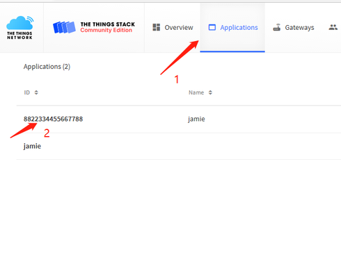
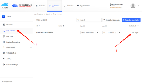
Successful access to the network will display the previous "join" operation point in time, access to the network failure will display "never".
(5) Configure protocol and send data, send serial data:
AU915:
(6) Viewing the frequency sent from the serial window
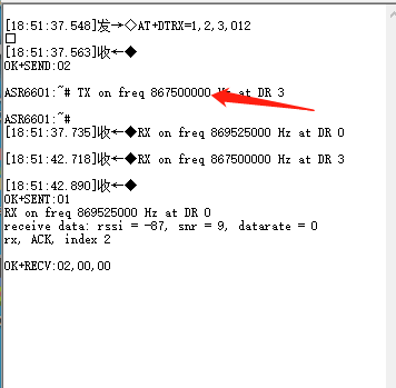
(7) Receive log print messages against the Raspberry Pi gateway

Check the address address, confirm that it is the same as the set node address dev address, and the frequency and serial port printout information are also the same.
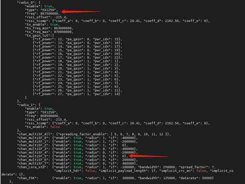
According to the frequency 876.5, checking the configuration file related to the Raspberry Pi gateway yields a current channel number of 5, which is consistent with the printed information.
(8) Use other nodes for data uploading to the Raspberry Pi gateway, which will use the corresponding channel number for decoding at different frequencies.


