Currency
Toggle Nav


FSCOPE-500K DIY OSCILLOSCOPE
$6.99
Availability:
Out of stock
SKU
CQN500KP2
Weight
85g

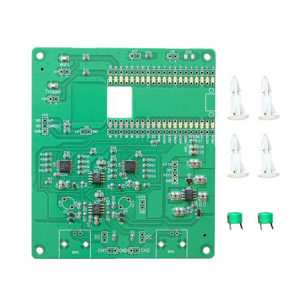
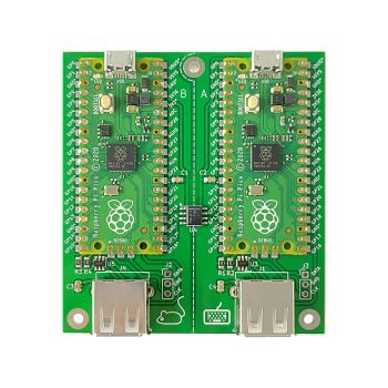
Combine the FSCOPE-500K with a Raspberry Pi Pico or Pico W and the Scoppy Android app to create a 500kS/s oscilloscope.
Frequently Bought Together


Combine the FSCOPE-500K with a Raspberry Pi Pico or Pico W* and the Scoppy Android app* to create a 500kS/s oscilloscope.
Simply solder a Pico (or Pico W) to the board together with 0.1" header pins and the supplied trimmer capacitors and you have a 500kS/s oscilloscope.
Note: Android device, RPi Pico, probes,BNC connectors and headers are NOT included
Features and Specifications
- Up to 500kS/s sample rate (250kS/s with both channels enabled)
- Maximum analog bandwidth: 150kHz
- Record length: 2048 samples per channel in RUN mode, 100kS total for single shot captures
- Input Impedance: 1MΩ / 22pF
- Maximum Input voltage range: +/- 6V (1X probes)
- Coupling: AC/DC
- Connectivity: USB, Wi-Fi*
- Display Modes: YT, FFT, FFT+YT, X-Y, X-Y+YT
- Trigger Types: Rising edge/falling edge
- Trigger Modes: Auto/Normal (Run Mode + Single captures)
- Cursors: YT and FFT horizontal and vertical cursors
- On-screen measurements: Vmin, Vmax, Vpp, Frequency, Period, Duty
- Snapshot measurements (screen or sample record): Mean, DC RMS, AC RMS
- Export data format: CSV
- Access to all pins of the Raspberry Pi Pico
- Signals can be input via 0.1” header pins or BNC connectors*
- Signal generator - square wave up to 1.25MHz, sine wave - 1kHz
- AC and DC coupling of the input signals
- Indicator LEDs: Status, Wi-Fi and Trigger
- FFT Window functions: Hann, Hamming, Blackman, Rectangle
- FFT Vertical units: dBm, dBmV, V
- Logic Analyser: 25MS/s (requires soldering extra headers to the board - not supplied). No protocol decoding as yet.
- See the Scoppy project on GitHub for the features of the Scoppy oscilloscope firmware and Android app
More Information
FSCOPE-500K assembly instructions
FSCOPE-500K opeating instructions
What You'll Need
- An Android device that's running Android version 6.0 (Marshmallow) or higher. The device must also support USB OTG (On-The-Go) - most modern phones/tablets do. If you are able to install the Scoppy app from the Play Store then (according to Google) it does support USB OTG.
- A compatible OTG cable/adapter (not supplied). Even if you are planning to use Wi-Fi, we recommend having a compatible OTG (On-The-Go) cable so you can access the firmware settings in the event you can't connect via Wi-Fi (eg. if your Wi-Fi password changes or the Wi-Fi settings in the firmware were entered incorrectly). The OTG adapter plugs into the USB port of your Android device.
- If your phone/tablet has a Micro-USB port then you will need a Micro-USB adapter. Here is an example: https://www.elecrow.com/usb-otg-host-cable-micro-b-otg-a-male-to-a-female-p-1543.html
- If your phone/tablet has a Type-C USB port then you will need a Type-C adapter (USB-2 or USB-3 will both work)
- A Raspberry Pi Pico or Pico W
- Header pins for the channel inputs, DC coupling and the signal generator. See the assembly instructions for details.
- Header pins and sockets for connecting the Pico or Pico W to the FSCOPE-500K. These are not required if the Pico (or Pico W) is to be soldered directly to the FSCOPE-500K.
- Header pin jumpers.
- BNC connectors. These are only required if you plan to use oscilloscope probes. Dupont wires can be used as probes instead.
Please Note
- Raspberry Pi Pico (or Pico W), Android device, header pins, BNC connectors and scope probes are NOT included
- Use of the second channel requires the premium version of the Scoppy Android app (approx US$3 in-app purchase)
- Wi-Fi functionality is only available with a Raspberry Pi Pico W (ie. not a Pico)
- Some assembly required
Features
Triggering
The FSCOPE-500K supports AUTO and NORMAL trigger modes and RISING EDGE and FALLING EDGE trigger types. The trigger level is set either by dragging the trigger indicator, tapping the trigger level buttons or tapping the trigger badge at the bottom of the screen. Long-pressing the LEVEL button will set the trigger level to the center of the displayed waveform.
Cursors
Horizontal and vertical cursors are available in both YT (ie. normal oscilloscope) and FFT modes. In YT mode, the horizontal (X) cursor measurements include position, period and frequency. Vertical (Y) cursor measurements include the voltage and the delta between the two cursors.
FFT

Note: Android device, RPi Pico, probes,BNC connectors and headers are NOT included
- Window functions: Hann, Hamming, Blackman, Rectangle
- Vertical units: dBm, dBmV, V
- Separate adjustments for start/stop frequency, center, span and vertical scale and position
- Tap and hold the SPAN, CENTER, SCALE and POSITION buttons to set these to their default values
- The FFT and YT views can be displayed simultaneously
X-Y Mode

Note: Android device, RPi Pico, probes,BNC connectors and headers are NOT included
Standard X-Y mode as found on most oscilloscopes. Also includes a LINES option to join all samples points with lines instead of displaying individual dots. This can make the output look much nicer for some signals.
The X-Y mode view can be displayed simultaneously with the YT waveforms.
Roll Mode

Note: Android device, RPi Pico, probes,BNC connectors and headers are NOT included
Displays the waveform data as it is captured instead of waiting for the complete waveform record. Roll mode is used when the sample rate drops below 1kS/s.
Tapping the ROLL button will enter roll mode and set the Time/Div to 1s/div. Tapping it again will leave roll mode and set the Time/Div back to its previous value.
Single shot captures
Pressing the SINGLE button will capture a single waveform record of up to 100k samples. Can be used with either AUTO triggering (to capture the waveform immediately) or NORMAL triggering (to capture the waveform after a trigger event occurs).
8-channel Logic Analyzer
Headers can be soldered to the board to access the Logic Analyzer inputs. The logic analyzer sample rate is 25MS/s and the maximum voltage is 3.3V.
Protocol decoding is not available but the waveform record can be saved and imported into other software (eg. sigrok/pulseview).
AC/DC Coupling
Removing the jumpers from the DC coupling pins will enable AC coupling.
Measurements
On screen measurements include Vmin, Vmax, Vpp, Frequency, Time (Period) and Duty Cycle for each channel. Tapping the measurements will open the configuration screen. The configuration screen can also be accessed via the channel badges.
Measurements can be displayed for a single waveform (snapshot). These snapshot measurements can encompass the entire sample record or just those samples displayed on the screen. The measurements available include Vmin, Vmax, Vpp, Vmean, Vdc-rms, Vac-rms, Frequency, Period and Duty Cycle. The snapshot measurements can be displayed by long-pressing the on-screen measurements or via the channel badges.
Signal generator
The signal generator can produce square waves of between 10Hz and 1MHz or a PWM encoded sine wave of 1kHz. The PWM encoded sine wave can be converted to an analog sine wave using the onboard low pass filter.
Open Source Hardware
The hardware is open source and of course you can install your own firmware onto your Pico or Pico W board (however, if you do this you are on your own as we can't provide support for custom firmware).
Write Your Own Review
Bestselling Products You May Like


New Products You May Want

Warranty
Service
VIP Distributor
Discount
Professional
Tech Support
Fast
Delivery
×
 Add to cart successfully!


Customers Who View This Item Also Bought