Currency
Toggle Nav

ESP8266 Wireless Toilet Usage Indicator (Smart Home)
April 06, 2016

As a engineer, it’s lucky enough to work for a company that make up with a group of maker. Because we often encounter some problems in our life, our manger allow us to put our creativity into full play due to the opened atmosphere, we can build lots of funny applications to solve the problem.
Recently, we have recruited a number of new workmates, so there have something embarrassing happened, sometimes when I went to the toilet and found that both of the two toilets are occupied, once I complain to kevin about it, then he said: If there is a kind of indicator LED like an airplane toilet lights, so we could know whether the toilet be used. Good idea! I praised him: “hey! Boy! You are really a genius! ” OK, now we have prepared everything, let think about that if you want to achieve remote control, what we need to do? The first role is the most popular platform board -ESP8266, as it happens, we have get some ESP8266 IOT Board just recently, it can achieve wireless control easily, and the most important thing is it cheap enough.
The main function of the project is when the toilet was using, the indicator will show the state of the toilets remotely, just like the toilet indicator in the plane.


Technical Solution
So how do we achieve a function that can feedback the status of the toilet at real-time? Firstly, we need a ESP8266 IOT board as a main controller. ESP8266 IOT board has powerful calculative ability that often play as a indepentdent MCU. We have two toilets, so we need three stations, two for toilets and the rest one for status indicator.
The technical solution as the attached image. ESP8266 server should be set as AP mode, it can build a TCP communication with other ESP8266 clients. The clients should work for reading the status of sensors, then feedback to server. and server will control LED to display it.
With them, this application is much simpler to build, now let’s witness the birth of the practical use toilet indicator LED!

Bill of materials
We get the following things, they are all required modules:
This new ESP8266 microcontroller contains a Tensilica chip core as well as a full WiFi stack. You can program the microcontroller using the Arduino IDE for an easy-to-run Internet of Things core. We added a connector for 3.7V Lithium polymer batteries and built in battery charging.
3: 3.7V 800mAh Lithium Polymer Battery x 2
4: 3.7V 1500mAh Lithium Polymer Battery x 1
5: 8 mm LED x 4
6: Double Side ProtoBoard 2 * 8cm x 1
7:100Ω resistor x 4
8:Jumper wire x 11
9:Pin Header x 1
1:Indicator LED


 Are you ready? First of all we need to make the indicator LED, it has a funcation: indicate the toilet use status with LEDs, if the toilet has not been used, the green led will light up, if used, the red LEDs will light up with the green one go out.
Have you seen that double side protoboard and LEDs? That’s right, we need to weld the four leds on the protoboard. it makes the led and circuit integratively. nice and save more space. They are used to display the staus of toilet I and toilet II, each toilet need two LEDs- a green one and a red one, weld them as picture shows.
Then you need to weld four 100Ω resistors, both of them should be weld with the positive pole of LEDs. and all the negative pole of LEDs should be connected to GND.
At last, there has a widget- a 5 pin header. It will provides convenience for connecting the indicator LED to ESP8266IOT board with jumper wires, you can refer to the above pictures about the connection, those have been signed with red line for you.
2:Server node


Now, we start to connect the LEDs Indicator with ESP8266 IOT board, only five wires to achieve it and i have marked them with corresponding ports. it's easy to finish and don't be careless.
At last we need to power it, it requires 3.3V work voltage,a battery or a usb cable? we finally choose battery so that we can make it become a independent mobile device, a 3.7V 1500mAh LiPo battery is the best choice, we can use battery with it convenient due to its special battery interface. Also the size of battery is compatiable with the board, so if you want to make your device become more smaller, you can stack the board on the battery as shown.
3:Client node


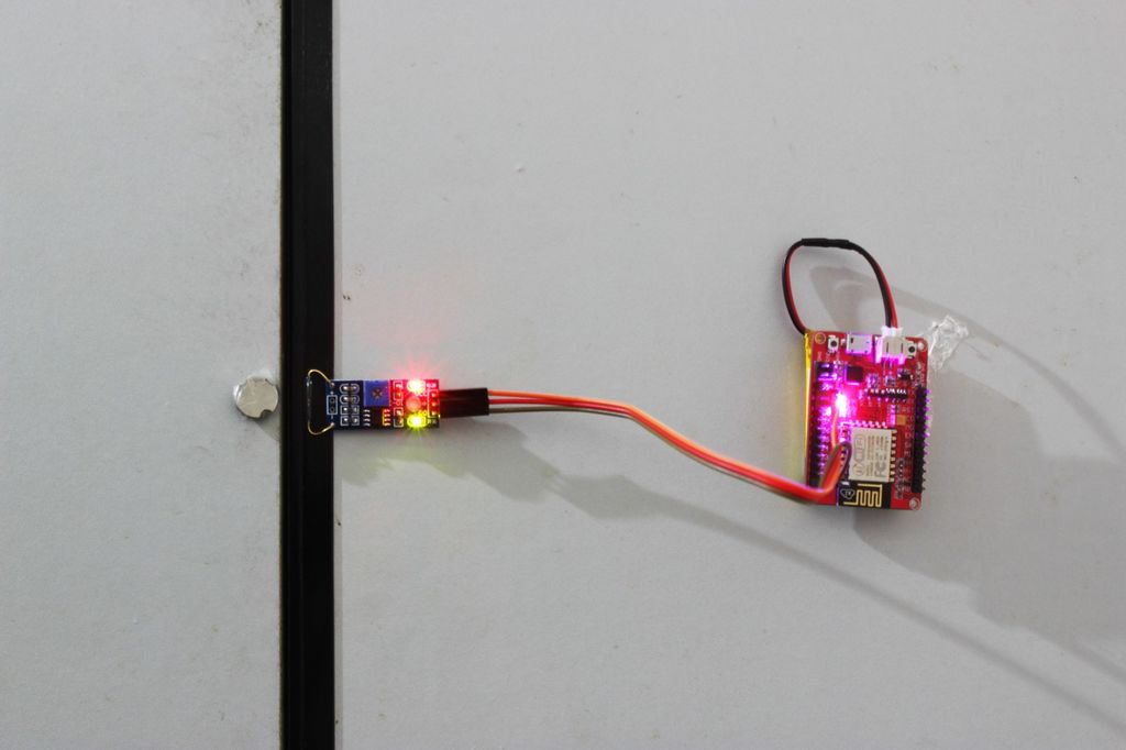
Now, the last part to deal with- two client nodes, it can obtain the toilet usage status, how to achieve this? The most direct way is to monitor the change of door, so we choose the reed switch module, this reed switch module used a small device called a reed switch. When the device is exposed to a magnetic field, the two ferrous materials inside the switch pull together and the switch closes. When the magnetic field is removed, the reeds separate and the switch opens. so if we utilize the magnetic bead to use with the reed switch, it's easy to implement the function. it can response the magnetic bead sensitively. Just three female to female jumper wires for connecting it to ESP8266 IOT board, VCC connect to VCC, GND connect to GND, D0 connect to D0. It needs a power too, we choose a 3.7V 800mAh LiPo battery for "him", For saving space, you could attach the battery with ESP8266 IOT board too.
Ok, all of the hardware has been prepared!
4:Programming


It's time to upload the program to these board, at first we need to write the program, we choose the software tool- LuaEditor to help us, we write three codes for three modules as above pictures show. next i'll teach you how to write program with this software.
First, open the software, then bulid a new code file, next write the program at the right blank part of window, at last you need to save it into a fixed file as "lua" format then have a compilation.
Upload the program


Of course, if you want to use them ,you need to upload the "Server code" onto the ESP8266 server node station, and "Client1" code for the ESP8266 client node station which is installed on toilet I. "Client2" code for the station that be installed on toilet II.
You can download these codes in there and i'll upload the server node code for example. First you need connect the ESP8266 IOT board with computer by usb cable, then open the ESP8266 LuaLoader 0.9(Tools and firmware), set the serial port first, then connect and open the program file, do the file finally. Also the Client code uploading according to this step, when you done it, you can see the change of the onboard LED in the above pictures. It shows that normal work of the program.
5:Installation


If we want to fix the client node with a door, a tape is necessary.
I have done it, look at this picture, but I always felt something missing, it looks so exposed and disgusting. So we decide to stick a poster on it, and we choose that one as the photo shows, how do you like it? It shows toilet is be used when the color of the pedestal pan turn red to purple. Have you feel better than before? Hey! superman! don't let us wait too long! Funny and friendly!
6:Optimization


But i'm so sorry for that what case we choose to hold the server node looks so poor, we can't found a delicate house for it, yeah! Because we are just boorish man, maybe serch for help to our female colleagues next time seems be a better choice. we decide to install the server node on wall, that would be more conspicuous for all staffs.
Fortunately, the white wall give me inspiration and i found a remedial measure to decorate the house- package it with a white paper, it looks better than before, don't you think so? Well done!
7:Conclusion
We solve this problem perfectly , our office will become more intelligentized and humanized!
ESP8266 IOT board is a powerful platform tool! you can even expand to four toilet using, and it can apply on lots of projects too. you need to use your creativity to create more.
"idea" changes your life!
Note: All the program and software tools could be download at the last of essay.