Currency
Toggle Nav

Behind the Scenes: How We Test the LoRaWAN Module before shipping
May 29, 2025

Before any LoRaWAN module leaves our facility, it undergoes a meticulous multi-step testing process designed to guarantee stability, long-term reliability, and optimal performance across real-world applications. At Elecrow, quality is not just a promise, but a standard upheld through rigorous testing and professional tools.
To ensure each module meets the demands of smart agriculture, industrial IoT, and urban infrastructure, we combine hands-on inspection with professional testing equipment. We employ spectrum analyzers, signal generators, vector network analyzers (VNAs), and RF shielded test enclosures. These tools allow us to accurately measure RF output, verify signal integrity, and confirm compliance with LoRaWAN protocol specifications.
Today, we’re giving you a behind-the-scenes look at how we test LR1302 PCBA boards for LoRaWAN gateways using our custom LoRaWAN HAT and Raspberry Pi.
RF Test Equipment and Functions on Our Bench - Brief Overview
*Spectrum Analyzer
Used to view the LoRa module's transmission spectrum in real-time. By scanning the target frequency band (e.g., 868 MHz/915 MHz), we can observe peak signal power, bandwidth occupancy, and identify any unwanted harmonics or spurious emissions.
*RF Power Meter & Test Fixture
The test fixture physically secures the module under test and connects it to the power meter, enabling precise measurement of its average output power while ensuring consistency across multiple measurements.
*Control Host & Display Terminal - PC/Raspberry Pi + Monitor
A laptop (or Raspberry Pi) runs automated scripts to centrally control the spectrum analyzer and power meter. Test results are displayed in real-time on a separate screen, and a simple report can be generated at the end.
Test Capability Description
At Elecrow, our RF testing capabilities extend far beyond any modules. We possess the expertise and equipment to verify a wide array of LoRa solutions. The following table showcases a selection of LoRa-related modules designed and manufactured by Elecrow. The inherent diversity in these modules—spanning various core LoRa chips, functionalities, and operational frequencies—demonstrates our comprehensive in-house testing coverage and our capacity to ensure the quality of a wide spectrum of RF hardware.
| Elecrow Module Model | Core LoRa Chip | Module Type | Supported Bands/Frequencies | Key Features/Applications |
|---|---|---|---|---|
| LR1302 LoRaWAN Gateway Module (SPI EU868) | Semtech SX1302 | Gateway Module | EU868 (European standard, 863-870 MHz) | LoRaWAN Gateway Core |
| LR1302 LoRaWAN Gateway Module (SPI US915) | Semtech SX1302 | Gateway Module | US915 (North American standard, 902-928 MHz) | LoRaWAN Gateway Core |
| Elecrow nRF-LR1110 Wireless Transceiver Module | Semtech LR1110 + Nordic nRF52840 | Transceiver Module | Sub-GHz LoRa (150-960 MHz), 2.4GHz (G)FSK | LoRa, GNSS, Wi-Fi Scanning |
| Elecrow nRF-LR1262 Wireless Transceiver Module | Semtech SX1262 + Nordic nRF52840 | Transceiver Module | Full Band (150 MHz - 960 MHz) | Low-Power Long-Range LoRa |
| Elecrow nRF-LR1121 Wireless Transceiver Module | Semtech LR1121 + Nordic nRF52840 | Transceiver Module | 2.4GHz LoRa, S-Band LoRa, 2.4GHz (G)FSK | 2.4GHz LoRa, GNSS, Wi-Fi Scanning |
| LR1262 LoRaWAN Node Module | Semtech SX1262 | LoRaWAN Node Module | Full Band, typically 433/470/780/868/915 MHz | LoRaWAN End Node |
| Elecrow nRF-LLCC68 Wireless Transceiver Module | Semtech LLCC68 + Nordic nRF52840 | Transceiver Module | Sub-GHz (150 MHz - 960 MHz) | LoRa-derived modulation for (G)FSK |
| LR1262 Long Range LoRa Wireless Transceiver Module | Semtech SX1262 | Transceiver Module | Wide Frequency Range (150MHz - 960MHz) | Ultra-Low Power IoT, Industrial |
| LRCC68 Long Range LoRa Wireless Transceiver Module | Semtech LLCC68 | Transceiver Module | Wide Frequency Range (150MHz - 960MHz) | Ultra-Low Power IoT, (G)FSK Apps |
(All the Modules you can find here: https://www.elecrow.com/iot/lora/module.html)
Our flexible test setups, including the professional tools mentioned earlier, allow us to meticulously evaluate each of these distinct module types—and indeed any LoRa-based module we design—for optimal transmit power, spectrum purity (harmonics/spurious emissions), occupied bandwidth, and receive sensitivity. This ensures we meet R&D, certification, and small-batch production needs with high confidence.
Step by step to see how we do
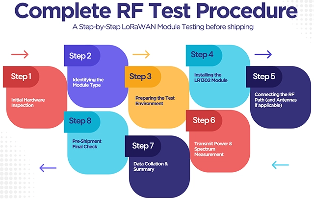
Complete RF Test Procedure
Step 1: Initial Hardware Inspection
Each module’s journey begins with a careful visual inspection. We take the LR1302 PCBA as example, then flat and check for common hardware issues: missing or misaligned components, cold solder joints, components that are placed too high, or any physical irregularities. If a board shows any defect, it’s marked as a nonconforming unit and placed aside for repair. Only boards that meet our visual standards proceed to the next step.
Step 2: Identifying the Module Type
The LR1302 module comes in four configurations, based on interface type and frequency band: SPI915, SPI868, USB915, and USB868. Each type is identified by the position of specific resistors on the board. For example, if the resistors are placed near the USB and 915 MHz markings, the module is identified as a USB915 type. This resistor-based labeling allows our engineers to quickly classify and set up the test accordingly.
Step 3: Preparing the Test Environment
We use a custom LR1302 LoRaWAN HAT designed for the Raspberry Pi as the foundation of our testing platform. The HAT is mounted securely on a Raspberry Pi, which is then connected to a monitor, keyboard, and mouse. Once the setup is in place, we power on the system and prepare to evaluate the module.

The HAT is mounted securely on a Raspberry Pi
Step 4: Installing the LR1302 Module
The LR1302-PCBA is gently inserted into the HAT, and a dedicated test jig—often referred to as a test handle—is used to apply even, downward pressure to ensure a stable connection between the module and the HAT. It’s crucial to avoid movement during this stage, as even slight misalignment could cause intermittent contact or inaccurate test results.

LR1302-PCBA is gently inserted into the HAT
Step 5: Connecting the RF Path (and Antennas if applicable)
For conducted RF measurements, the module's RF output on the HAT is connected via a calibrated RF cable to the spectrum analyzer or RF power meter. If a preliminary over-the-air (OTA) functional check is performed, or if GPS functionality (on PCBA variants that include it) is being tested, the appropriate antenna(s) (e.g., 868 MHz, 915 MHz, or GPS) are connected. With everything in place and securely attached, the module is ready for software-side testing and performance verification.
Step 6: Transmit Power & Spectrum Measurement
To verify the LR1302 module’s transmit performance, we first configure the spectrum analyzer with the center frequency matching the module’s band (e.g., 868 MHz), a span of 5–10 MHz, and an RBW of 100 kHz. Enabling Max Hold allows us to capture the peak envelope over time. Next, on the Raspberry Pi we run a Python script that sets the spreading factor (e.g., SF7), bandwidth (125 kHz), coding rate (4/5), and transmit power (e.g., +14 dBm), causing the module to continuously transmit. On the spectrum analyzer, we move the marker to the carrier peak to read the instantaneous power (in dBm), then switch to the second and third harmonic frequencies to ensure harmonics remain below −36 dBm. Finally, we disconnect the spectrum analyzer and connect the same RF line to the RF power meter to read the average output power, correct for cable loss, and compare it against the spectrum analyzer's peak reading and expected values—confirming the module’s output is within ±1 dB of target.
Step 7: Data Collation & Summary
After completing the transmit measurements, we create a simple spreadsheet (Excel or Google Sheets) to log key parameters: module type (SPI915/SPI868/USB915/USB868), peak power (spectrum analyzer) versus average power (power meter), occupied bandwidth (95%), and whether harmonics comply (below −36 dBm). If a sensitivity check was performed (using a calibrated signal generator and verifying packet reception), we also record that data point. If an antenna sweep (S11 measurement using a VNA) was done for specific batches or R&D purposes, we note the results. We then export a concise report—either via script-generated CSV/PDF or by screenshot—documenting the module’s test results, the date, and instrument models. Based on these results, if the transmit power deviates by more than ±1 dB, we inspect the RF path or solder joints; if harmonics exceed limits, we check for PCB shorts or filter damage. Once transmit power, bandwidth, and harmonics are within spec and the module communicates reliably, we deem it acceptable.
Step 8: Pre‑Shipment Final Check
Before shipping, we randomly select one or two modules that passed earlier tests and repeat the key transmit configuration (e.g., SF7/125 kHz at +14 dBm) to ensure consistent performance. We then label each batch or include a brief summary in the documentation, indicating the test date, module type, and whether transmit power and harmonics met requirements. If a customer requests, we compile the spreadsheet data from all units into a single summary document; otherwise, retaining the CSV or screenshots is sufficient for internal records. This final check—focused on a quick re‑validation of critical parameters—ensures no module unexpectedly drifts out of spec before delivery.
Every LR1302 module that passes through this process is thoroughly vetted for field-ready performance. Whether destined for smart agriculture, industrial sensing, or city-scale LoRaWAN infrastructure, each unit is built and tested with care. Stay tuned as we continue to share more behind-the-scenes insights into how we build IoT hardware you can trust.
If you are interested in LoRa Modules, check out Elecrow’s Giveaway and PCB Assembly Sponsorship, you could get a free module for your next project!