Currency
Toggle Nav

Behind the Scenes: How We Test the LR1302 LoRaWAN Module
May 29, 2025

Behind the Scenes: How We Test the LR1302 LoRaWAN Module
Before any LR1302 LoRaWAN module leaves our facility, it undergoes a meticulous multi-step testing process designed to guarantee stability, long-term reliability, and optimal performance across real-world applications. At Elecrow, quality is not just a promise, but a standard upheld through rigorous testing and professional tools.
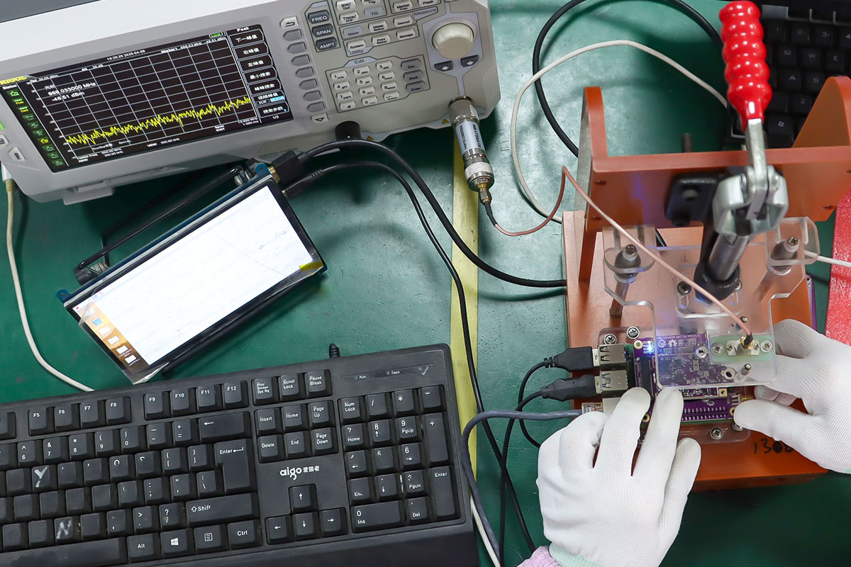
To ensure each module meets the demands of smart agriculture, industrial IoT, and urban infrastructure, we combine hands-on inspection with professional testing equipment. We employ spectrum analyzers, signal generators, vector network analyzers (VNAs), and RF shielded test enclosures. These tools allow us to accurately measure RF output, verify signal integrity, and confirm compliance with LoRaWAN protocol specifications.
Today, we’re giving you a behind-the-scenes look at how we test LR1302 PCBA boards for LoRaWAN gateways using our custom LoRaWAN HAT and Raspberry Pi.
Step 1: Initial Hardware Inspection
Each module’s journey begins with a careful visual inspection. We lay the LR1302 PCBA flat and check for common hardware issues: missing or misaligned components, cold solder joints, components that are placed too high, or any physical irregularities. If a board shows any defect, it's marked as a nonconforming unit and placed aside for repair. Only boards that meet our visual standards proceed to the next step.
Step 2: Identifying the Module Type
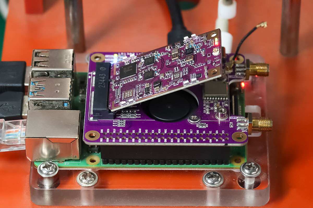
The LR1302 module comes in four configurations, based on interface type and frequency band: SPI915, SPI868, USB915, and USB868.
Each type is identified by the position of specific resistors on the board. For example, if the resistors are placed near the USB and 915 MHz markings, the module is identified as a USB915 type. This resistor-based labeling allows our engineers to quickly classify and set up the test accordingly.
Step 3: Preparing the Test Environment
We use a custom LR1302 LoRaWAN HAT designed for the Raspberry Pi as the foundation of our testing platform. The HAT is mounted securely on a Raspberry Pi, which is then connected to a monitor, keyboard, and mouse. Once the setup is in place, we power on the system and prepare to evaluate the module.
Step 4: Installing the LR1302 Module
The LR1302-PCBA is gently inserted into the HAT, and a dedicated test jig—often referred to as a test handle—is used to apply even, downward pressure to ensure a stable connection between the module and the HAT. It’s crucial to avoid movement during this stage, as even slight misalignment could cause intermittent contact or inaccurate test results.
Step 5: Connecting the Antennas
Finally, we connect the appropriate antenna based on the module’s frequency—either 868 MHz or 915 MHz. If GPS testing is required (for location-based modules), a GPS antenna is also connected. With everything in place and securely attached, the module is now ready for software-side testing and performance verification.

Every LR1302 module that passes through this process is thoroughly vetted for field-ready performance. Whether destined for smart agriculture, industrial sensing, or city-scale LoRaWAN infrastructure, each unit is built and tested with care. Stay tuned as we continue to share more behind-the-scenes insights into how we build IoT hardware you can trust.
If you are interested in LoRa Modules, check out Elecrow’s Giveaway and PCB Assembly Sponsorship, you could get a free module for your next project!