
Story
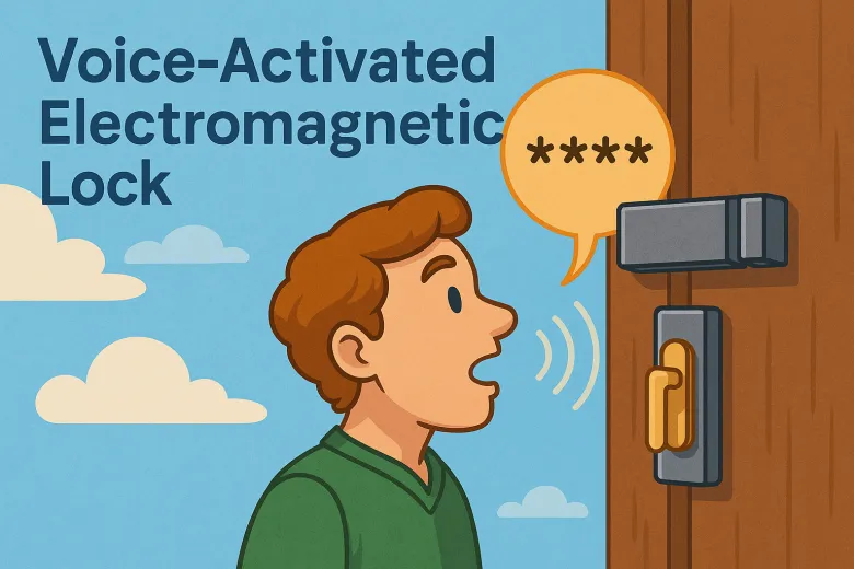
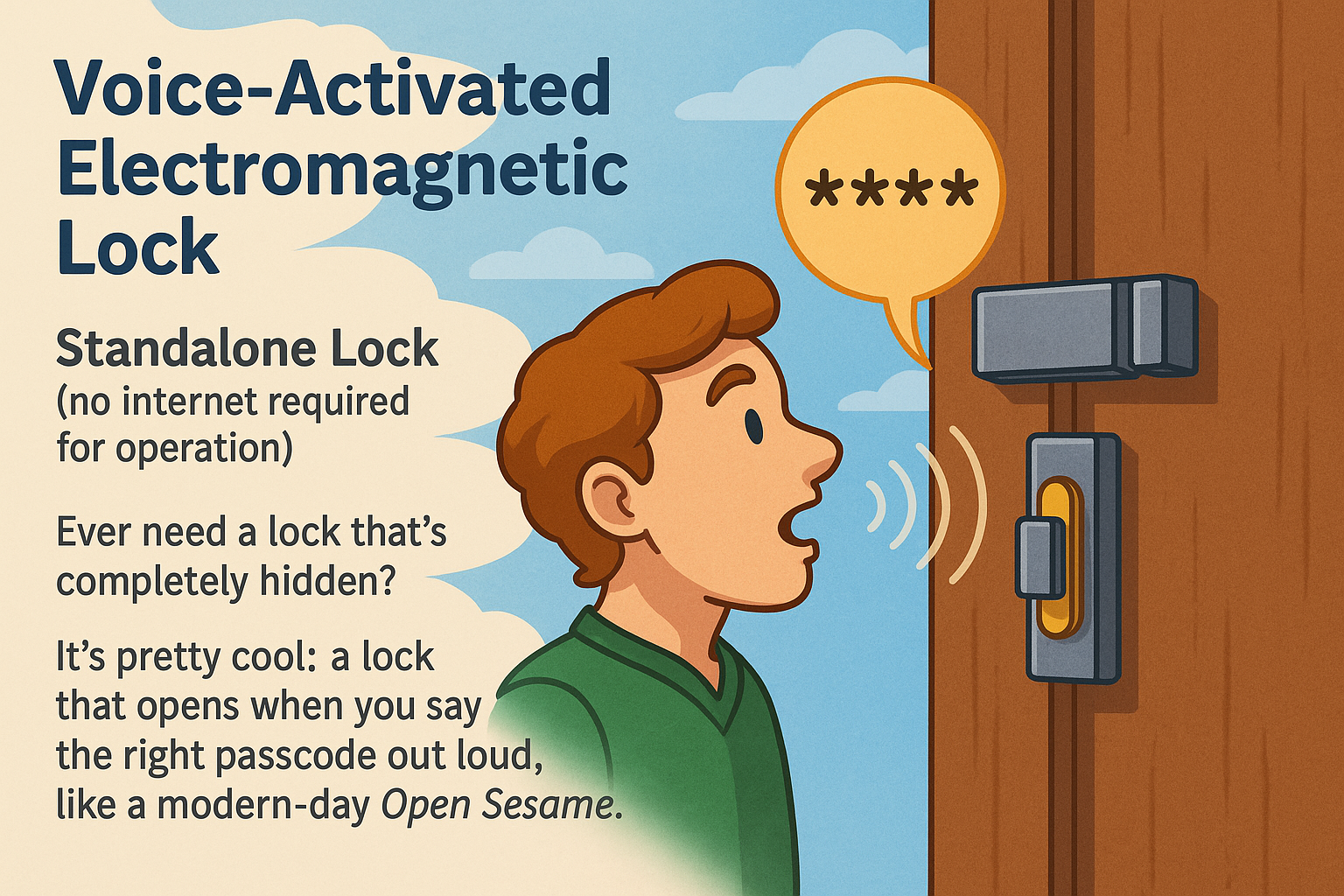
Imagine opening a lock without touching it—no buttons, screens, or keys. Just walk up, say the code, and the door unlocks, like a modern-day Open Sesame, magic from Ali Baba and the Forty Thieves.
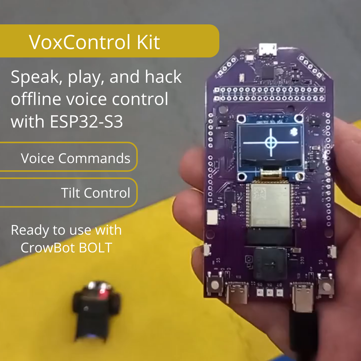
Such a device can easily be built using the GRC AI Robot Control board.
While primarily designed for robot control, its functionality is far broader: it comes preloaded with three applications:
- Robot control,
- Voice PIN, and
- Teacher 3+.
One of the built-in apps, VoicePIN, has multiple use cases.
It’s not just for creating a voice-activated lock but can also be used for
- securing data input,
- restricting access, or
- controlling any device.
For example, you could set a voice password to manage lighting, heating, or air conditioning in a Smart Home system.
In this article, we’ll focus on the simplest scenario: a step-by-step guide to creating an electronic lock that opens upon entering the correct voice PIN, using the built-in app and a standard electromechanical lock control module.
Required Components:
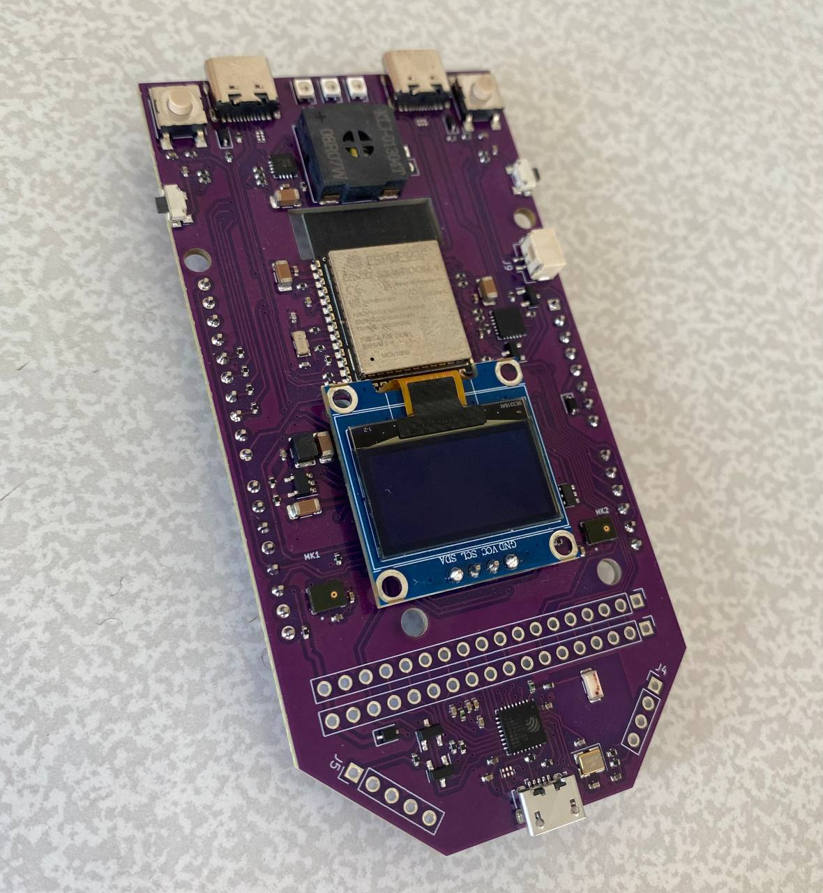
1. GRC AI DevBoard – a board with the VoicePIN app preinstalled
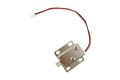
2. Electromagnetic latch lock (12V, 1.1A)
3. 12V 1A power supply – a wall adapter with a 5.5×2.5 mm plug
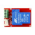
4. Lock control board: A 5V voltage regulator and a power switch to control the electromagnet

The lock control board performs two tasks:
- When connected to a power source, it supplies 5V to the GRC AI DevBoard via a regulator to power the board.
- It delivers 12V to the electromagnetic lock to open it upon receiving a signal from the GRC DevBoard. In other words, when the correct voice PIN is spoken, the GRC AI DevBoard triggers the transistor on the power board, sending voltage to the electromagnet and releasing the latch.

It can be assembled using the provided documentation or replaced with any suitable alternative—for example, a custom-built one using components from Electromagnetic Lock, and Crowtail-Relay 2.0.
The board’s schematic:

Next, let’s break down the wiring diagram for all components.

1. Connect the output on the power board (connector J3, pin 1) to the VIN pin on the DevBoard. This supplies the necessary 5V power.
2. Connect the ground (GND) from the power board (J3, pin 3) to the GND pin on the DevBoard.
3. To control the lock, link the GPIO_NUM_14 pin on the GRC DevBoard to pin 2 of connector J3 on the power board.
4. Connect the electromagnetic lock to connector J2 and the power adapter (with the plug) to J1 on the power board.
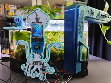
The fully assembled device looks like this:

VoicePIN Setup & Operation

Upon first boot, you’ll need to create a PIN code. The user must speak four digits aloud, and the DevBoard will memorize them after confirming the new password.
Once saved, the device will prompt you to repeat the code and verify it against the initial input. If correct, the lock will open with a confirmation message. If not, the lock remains closed, and the DevBoard will notify you of the incorrect input.
That’s it for now! As you can see, the project is simple but pretty fun.
As a bonus, I also want to show you another app called Teacher, which runs on the same dev board.
If you or your kids are learning English, it’s an awesome tool for practicing pronunciation:

")