Story
Description
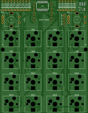
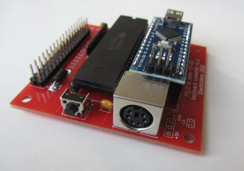
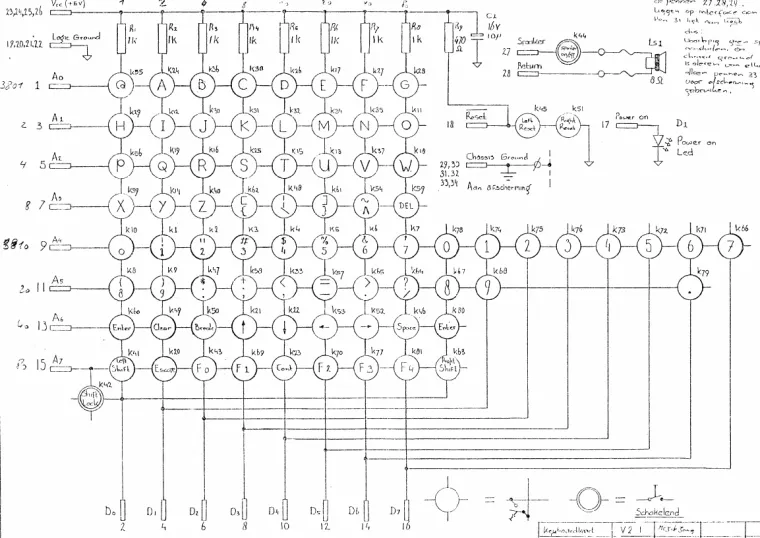
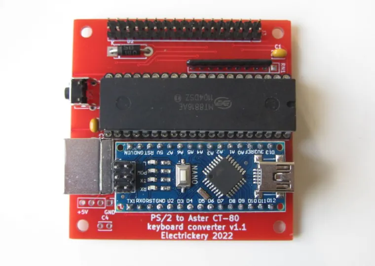
Keyboard matrices as often used in vintage computers can be hard to replace. This solution isn't cosmetically correct, but allows a cheap PS/2 keyboard to be used if the original is missing or damaged. The matrix-array chip used in this project allows for a 16x8 matrix, large enough for most situations.
It is based on an Arduino Nano and a MT8816 Analog Switch Array. The final PCB works, the Arduino sketch is functionally complete. Code can use some cleanup, and some keys have to be added (and tested).
More info at github: https://github.com/electrickery/ps2keyboard2matrix
The use case: https://electrickery.nl/comp/trs80/aster/
Details
A new github repo was added for the TRS-80 model 3, 4, and 4p:
https://github.com/electrickery/ps-2Keyboard2TRS-80. No board is planned, as I don't have a model 3 or 4, so I don't know how the connector looks physically. A modified board did work on the model 4p, This gives the confidence it will also work on the 3 and 4.
(Remarks on version 1.1 of the board
Boards usually come with their design faults, but for this version it is acceptable:
Diode D1, (below the Arduino) should be replaced by a shorting wire.
The resistor array uses only eight of the nine resistors, but unfortunately has to be a ten pin array. A 9 pin array can be used but must be mounted on pins 2 to 10, and a short has to be made between pin 1 and 2.)
Simple test for correct operation
(11/29/2022 at 17:55)
The board and firmware can be tested from the Arduino IDE, right after programming, requiring only a multi-meter:
Open the Serial Monitor and set the Baud rate to 115200. The prompt "PS2Keyboard to Aster CT-80 matrix V0.6" should appear.
Type ? <Enter>. The help text should appear.
Find pin 1 and 2 from the flat-cable header. These are at the top of the header, next to the text "J3".
Measure the resistance between the pins with an multi-meter. This should be very high, out of reach of most devices.
Type C00 <Enter> (One letter, two numbers)
Measure the resistance between the pins. This should in the range of 100 ohm.
Type O00 <Enter> (One letter, two numbers)
Measure the resistance between the pins. This should be very high, out of reach of most devices.
The first number is the column, the second the row. The former ranges from 0 to 7, the latter from 0 to F (entry in hex), but only the first eight are wired to the header.
(This project was reposted with the permission of the author. If you are interested in this project and want to know more, Please check: PS/2 keyboard to keyboard matrix | Hackaday.io
And if you want to explore more projects, please follow the author: fjkraan (Hackaday). He has many wonderful projects and is an excellent maker. Enjoy it)