Story
Detailed Project Description (Example for 4R Robotic Arm)
Introduction
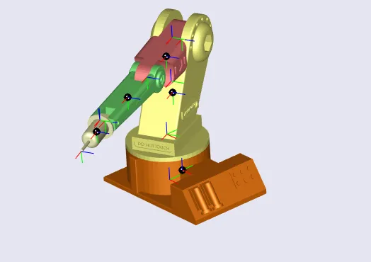
The 4R robotic manipulator arm is a mechanical system with four rotational joints (4 Degrees of Freedom) designed for performing precise positioning and manipulation tasks. This project focuses on the design, modeling, and simulation of the manipulator using CAD software and mathematical modeling tools. It serves as a platform for learning about robotics, kinematics, dynamics, and control systems.
Features & Design
-
Mechanical Structure:
-
4 rotational joints (shoulder, elbow, and wrist).
-
Modular CAD design using SolidWorks.
-
Lightweight structure suitable for educational and research use.
-
-
Kinematic Modeling:
-
Forward kinematics using Denavit–Hartenberg (D-H) parameters.
-
Inverse kinematics for calculating joint angles from end-effector position.
-
Workspace analysis to evaluate reachability.
-
-
Dynamic Modeling:
-
Equations of motion derived using Lagrange’s method.
-
Simulation of torque requirements for each joint.
-
-
Simulation Tools:
-
MATLAB/Simulink for simulation of kinematic and dynamic models.
-
Visualization of joint movements and trajectory planning.
-
Control algorithms (PID, trajectory tracking).
-
Working Principle
-
The arm consists of 4 revolute joints, giving it flexibility to move in 3D space.
-
A target position for the end-effector is set in Cartesian coordinates.
-
Using inverse kinematics, the required joint angles are calculated.
-
The control system sends commands to the joints (virtual or real actuators).
-
The manipulator follows the trajectory while respecting kinematic and dynamic constraints.
Program & Code
-
MATLAB/Simulink scripts for kinematic and dynamic modeling.
-
Simscape Multibody (optional) for 3D visualization of the robot’s motion.
-
Example algorithms for forward kinematics, inverse kinematics, and path planning.
Applications
-
Educational Robotics: Teaching students kinematics, dynamics, and robotic control.
-
Industrial Training: Foundation for robotic arms used in manufacturing and automation.
-
Research Platform: Extendable to 6-DOF manipulators, AI control, or ROS integration.
Step by Step Guide
-
CAD Design – Create the 4R manipulator arm model in SolidWorks.
-
Parameter Definition – Assign link lengths and joint constraints.
-
Forward Kinematics – Derive the position and orientation of the end-effector.
-
Inverse Kinematics – Solve for joint angles to reach desired positions.
-
Simulation – Implement kinematics and control in MATLAB/Simulink.
-
Validation – Test trajectories, workspace, and control stability.
-
Optional Fabrication – Build a prototype using servo motors and Arduino/ESP32.
Project Media
-
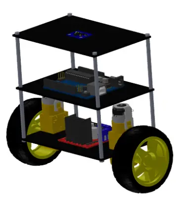
Images: CAD design of the 4R manipulator.
-
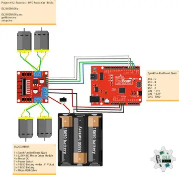
Schematics: Kinematic diagrams with D-H parameters.
-
Videos: Simulation of motion in MATLAB/Simulink