Add to cart
Board Type : GerberFile :
Layer : Dimensions :
PCB Qty :
Different PCB Design
PCB Thickness : PCB Color :
Surface Finish : Castellated Hole :
Copper Weight : 1 oz Production Time :
Total: US $
Elecrow community is a shared platform and we are not responsible for any design issues.

PCB Assembly

PCBA Qty: BomFile:
NO. OF UNIQUE PARTS: NO. of Components:
Assembly Cost: US $
Elecrow community is a shared platform and we are not responsible for any design issues.
Add to cart
3dPrintingFile : Size :
Unit : Volumn :
3D Printing Qty : Material :
Total: US $12.99
Elecrow community is a shared platform and we are not responsible for any design issues.
Add to cart
Acrylic Type : AcrylicFile :
Dimensions: Engrave:
Acrylic Qty :
Acrylic Thickness:
Acrylic Color:
Total: US $12.99
Elecrow community is a shared platform and we are not responsible for any design issues.
closed
user-img

Cristian Pitigoi

Published: Sep 06,2024

IR Remote CD4017

A project for automation, hobby and also learning.

ccc ccc
Copyright Info

Attribution-ShareAlike (CC BY-SA)

Read More⇒
  155
  1
  0
cover-img
 
  • thumbnail-img
  • thumbnail-img
  • thumbnail-img
  • thumbnail-img
 

Hardware Components

  • CD4017

    X 1

Tools, APP Software Used etc.

  • Kicad

Story

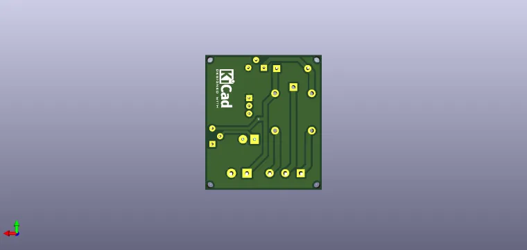
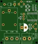
IR Remote CD4017


Remote control receiver for switching electrical and household appliances


The circuit shown can be used in households and facilitates the ON / OFF switching of the light bulb in the room, for example, using the remote control of the TV, DVD or any device controlled by an infrared remote control. Thus, the TV remote control becomes a

accessory with which you can control, from a distance (maximum 10 meters), the lighting in the room.

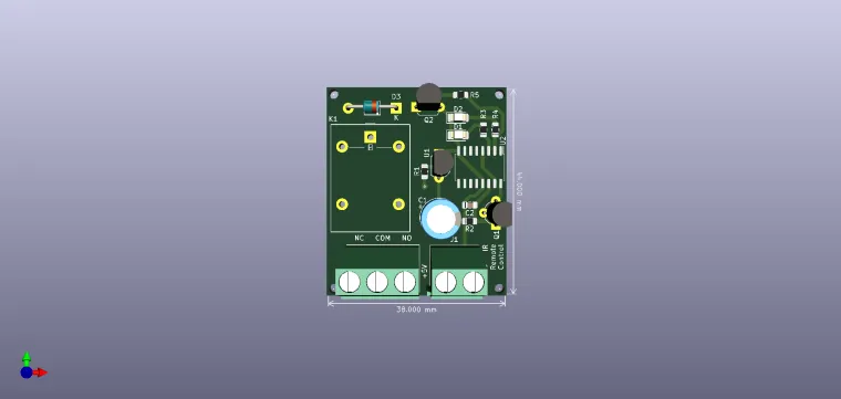
The working frequency of the TSO1738 receiver is 38kHz. The signal received from the remote control is picked up by U1, amplified by Q1 and applied to the clock pin (no. 14 of U2) of the counter 4017. As the output Q2 of the counter is connected to pin 15 (Reset), a press of a button the remote control switches the output Q0 to logical '1' (ie the relay is OFF), and the next press, the counting advances, Q1 switches to '1' and Q0 to '0' and the relay is activated. A new press causes Q2 to switch to '1', reset the counter and implicitly activate Q0, ie relay in OFF state. Capacitors C1 and C2 ensure switching

without error of the relay, the rectangular pulses, modulated by 38 kHz, from the remote control, being filtered by the capacitors.

The assembly will be powered by 5V. The relay must be operated with 5V. Its working contact, normally open, can be connected in parallel to the contacts of the light switch in your room.


Have fun with it !

Schematic and Layout
user-img

Cristian Pitigoi

+ Follow

Topic

View All
relay cd4017
  • Comments( 0 )
  • Like( 1 )
/1000
Upload a photo:
You can only upload 1 files in total. Each file cannot exceed 2MB. Supports JPG, JPEG, GIF, PNG, BMP

You May Also Like

View All