
Story
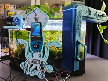
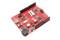
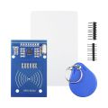
For educators in technical and science labs, ensuring the safety of students while providing access to high-risk electrical equipment is a constant concern. This project offers a robust, convenient, and secure solution: a device that safely locks away power to high-risk tools and grants controlled, timed access using an RFID card system. We call it the Smart Lab Lockbox. The core of this project is a metal enclosure that houses the electrical plugs, preventing unauthorized access. Inside, an IoT (Internet of Things) power bar is the central component for power management. This smart power strip is wirelessly controlled by an Arduino module, which acts as the system's brain. An external RFID card reader allows for secure user authentication, while a push button provides a manual override for early power cutoff. The design is simple, effective, and meets electrical safety regulations by keeping all high-voltage connections safely enclosed. This project provides a balance between convenience for you, the teacher, and safety for your students.
Features, Design, and Programming
The Smart Lab Lockbox boasts several key features designed for educational lab environments. The primary feature is RFID-based access control, which allows you to grant specific students or groups timed access to equipment. The system's 15-minute timer ensures that power is cut off automatically after the allotted time, preventing equipment from being left on accidentally. Students can also push a manual cutoff button to disable the equipment once they are finished.
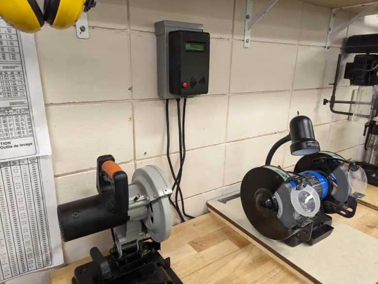
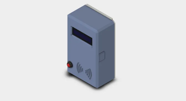
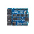
The device's design prioritizes safety and security. The use of a metal enclosure ensures that the electrical plugs are tamper-proof and fully contained, meeting electrical code standards. The Arduino, RFID reader, and button are mounted externally for easy user interaction. The system uses a common IoT power bar, making it easy to integrate with existing equipment.
The Arduino code is straightforward. When a student places their RFID card on the reader, the Arduino reads its unique ID (UID). This UID is compared against a list of pre-programmed, approved UIDs stored in the code. If a match is found, the Arduino sends a signal to the IoT power bar to turn on, and a 15-minute timer begins. The program also continuously monitors the manual cutoff button. If pressed, it immediately sends a signal to turn off the power bar, regardless of the remaining time. The code is modular, making it easy to adjust the timer duration or add/remove new RFID card UIDs.
Tutorial and Steps for Assembly
This tutorial will guide you through the process of building and setting up your Smart Lab Lockbox.
-
Connect all electrical components using the provided schematic. Ensure all connections are secure and follow proper safety procedures.
-
Upload the Arduino program to your Arduino board. Use the Arduino IDE to compile and upload the code.
-
Open the Serial Monitor in the Arduino IDE. This will allow you to see the output from the RFID reader.
-
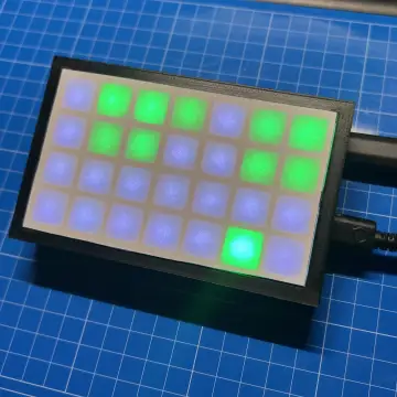
Read your RFID tags. Place each RFID card or key fob you want to use on the RFID reader. The unique ID (UID) of each tag will appear on the serial monitor.
-
Replace the placeholder UIDs in the Arduino code with the UIDs you just read. This is typically found on line 123 of the program.
-
Re-upload the code to the Arduino board and test your RFID cards to ensure they now activate the system.
-
3D print the enclosure parts using the provided .stl files. These files are designed to create a custom-fit cover for your system.
-
Use the provided template to mark and create the necessary holes in the metal Homeline circuit panel. This is where the RFID reader, button, and display will be mounted.
-
Secure the equipment inside the enclosure and finalize the assembly. The metal enclosure will now protect the electrical connections while the external components provide user access.
Debugging & Tips
-
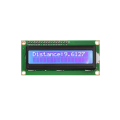
Power supply: Ensure your display is supplied with 3.3V and not 5V to prevent damage.
-
I2C address: If the 1602 display isn't working, you might need to change its I2C address in the code.
-
Libraries: If you get a compilation error, make sure all the required libraries (e.g., for the RFID reader and display) are installed in your Arduino IDE.
-
AI for code: Remember you can easily modify the code by using an AI assistant. Just attach your code file and describe the changes you need.