
Story
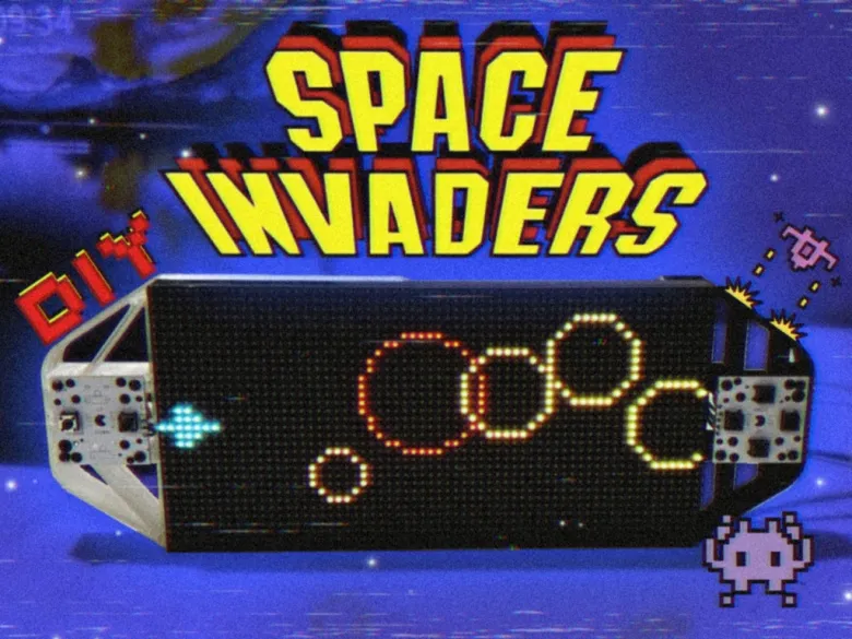
Greetings everyone and welcome back. meet PICO BLASTER.
Powered by the Raspberry Pi Pico and a vibrant 64x32 LED matrix panel, this unique Game Console transports players into the retro charm of "Space Invaders."
What started as a previous microcontroller-based project has now evolved into an exciting and highly interactive gaming experience: PICO Blaster. With strategic modifications, including a newly designed button control board and a custom-built frame, this revamped Game Console device redefines the retro gaming landscape.
PICO Blaster brings a fresh twist to the classic "Space Invaders" concept. Players control a spacecraft using a four-directional button PCB board, allowing seamless movement across the LED matrix display. As circular projectiles in three different sizes approach from the right side, the challenge is simple yet thrilling: shoot them down before they reach the ship. Armed with two types of weapons—rapid-fire bullets and a high-impact blaster—the game tests both strategy and reflexes.
Each projectile is color-coded based on size and difficulty: the smallest orange projectiles require a single bullet, medium yellow projectiles need two, and large red projectiles demand three hits to destroy. For players under pressure, the blaster offers a powerful advantage, capable of obliterating all projectiles in its path with a single shot, though limited by a 10-second cooldown.
PICO Blaster showcases a perfect blend of creativity and technical ingenuity, offering a rewarding experience for both players and developers.
This article dives into the project's journey, from hardware modifications to gameplay mechanics, unveiling what makes this game a standout achievement.
Materials Required
These were the materials used in this project:
- Custom PCBs
- Raspberry Pi PICO 2
- RGB Matrix 64x32
- IP5306 IC
- 10uF Capacitors
- USB Micro Port
- 18650 Lithium Cell
- 18650 Cell holder SMD version
- Push Buttons
- 3D printed Parts
PICO DRIVER
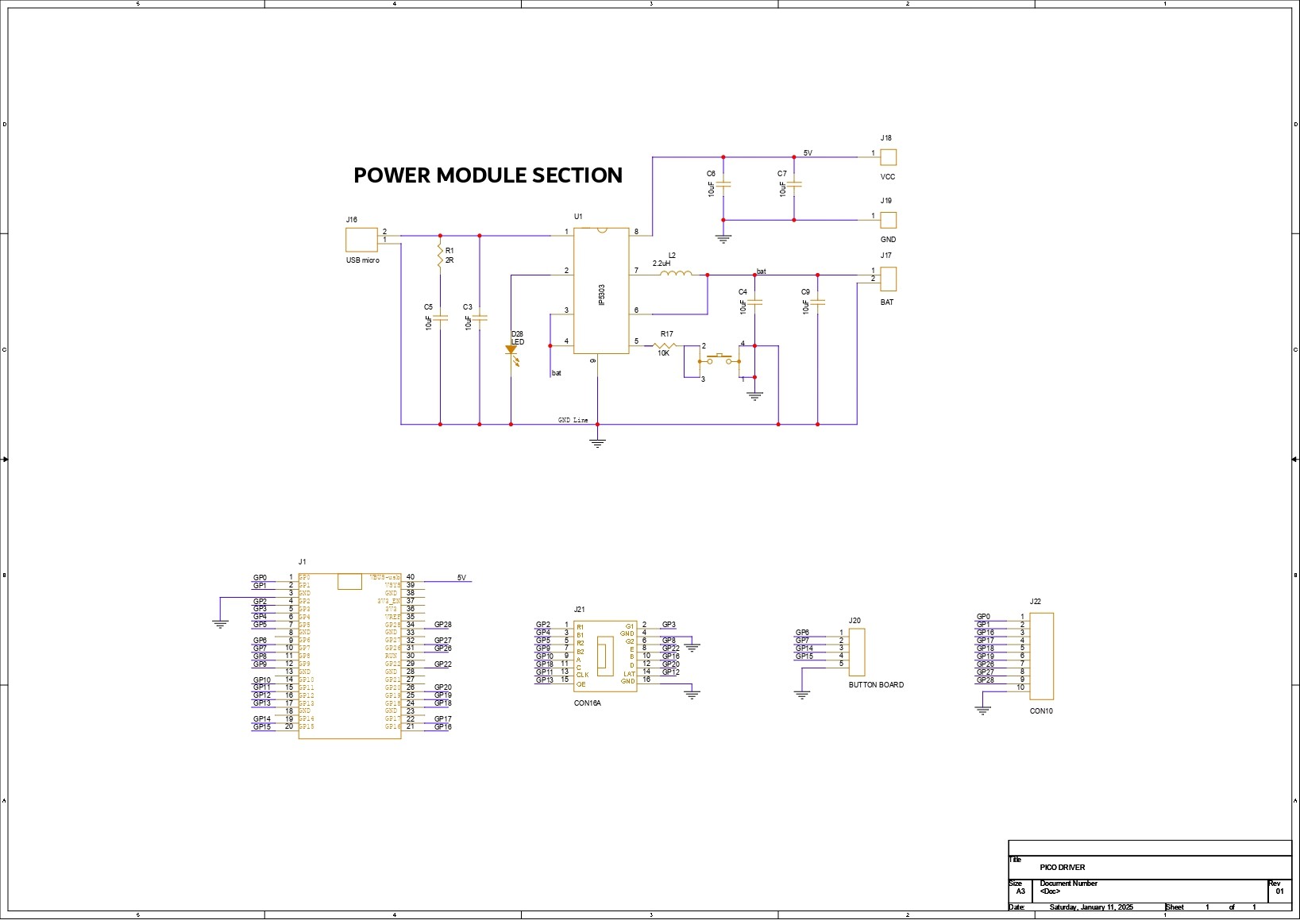
The main component of our console is the PICO Driver Board, which is essentially a breakout board for the PICO that allows us to connect an RGB matrix's HUB75 connector to the PICO. It also has a 3.7V Lithium Cell Power Management circuit, which ensures that the PICO and RGB matrix work at a consistent 5V.
Using our PCB Cad software, we first create the schematic for the PICO Driver Board design. In order to connect the Raspberry Pi PICO 2 to the Matrix's HUB75 connector, our setup consists of of a CON 16 connector.
We connected the matrix's HUB75 pins (CON 16) to the PICO's GPIO pins in the following order: A to GPIO19, B to GPIO16, C to GPIO18, D to GPIO20, E to GPIO22, CLK to GPIO11, LAT/STB to GPIO12, OE to GPIO13, R1 to GPIO2, G1 to GPIO3, B1 to GPIO4, R2 to GPIO5, G2 to GPIO8, B2 to GPIO9.
We added a CON5 connector for buttons, and its four pins are connected to PICO's GPIO6, GPIO7, GPIO14, and GPIO15. GND is attached to CON5's fifth pin. Each GPIO will be pulled to GND by the button board that connects to this CON5, and PICO can detect this as a button press.
We also incorporated a power management IC, the IP5306, a fully integrated multi-function power management SoC, to power the entire setup.
It can provide steady 5V 2.1A using 3.7V as an input, which can be used to power any 5V device—in our instance, the matrix and PICO 2.
You can checkout IP5306 Datasheet for more info: http://www.injoinic.com/wwwroot/uploads/files/20200221/0405f23c247a34d3990ae100c8b20a27.pdf
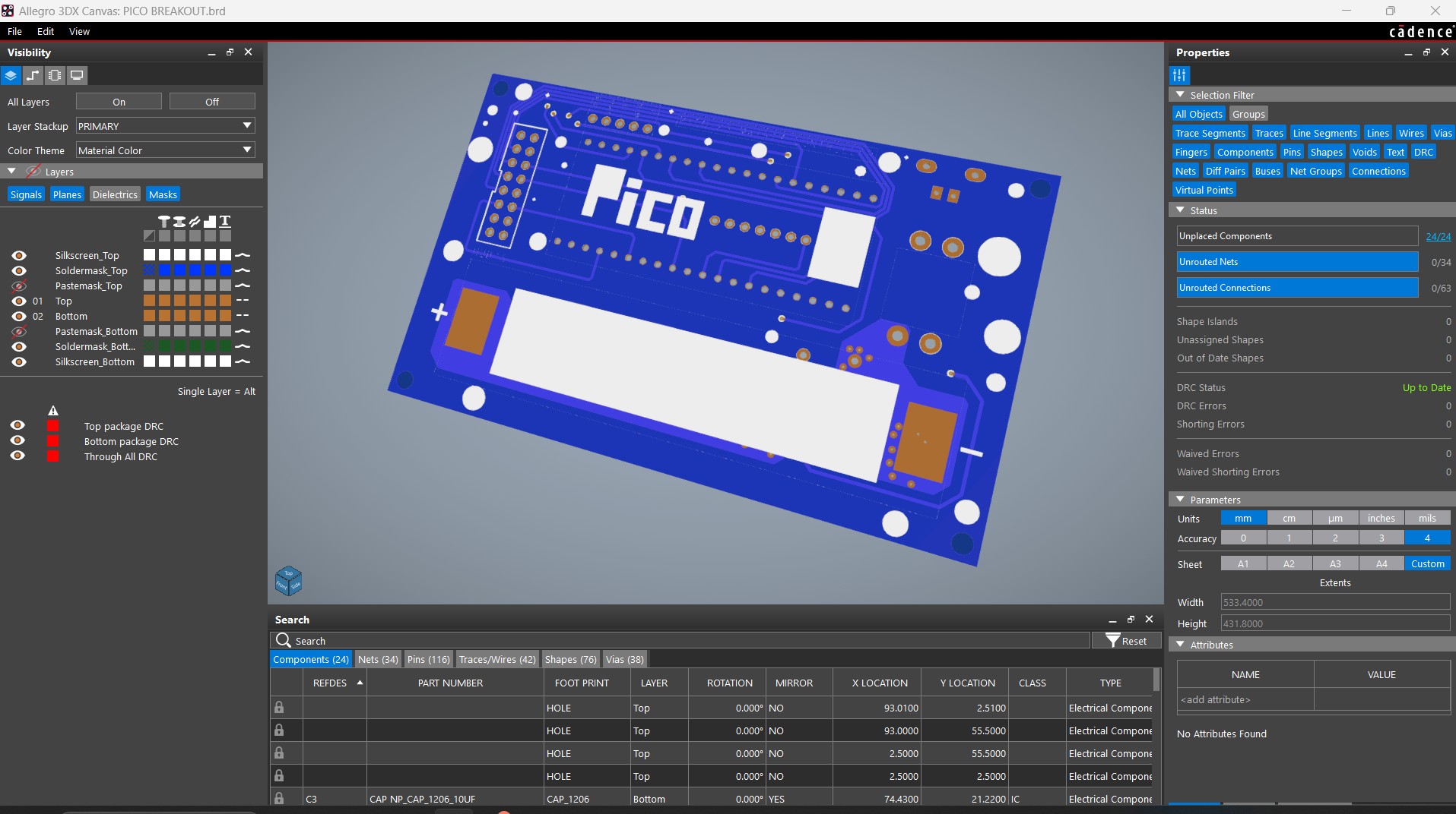
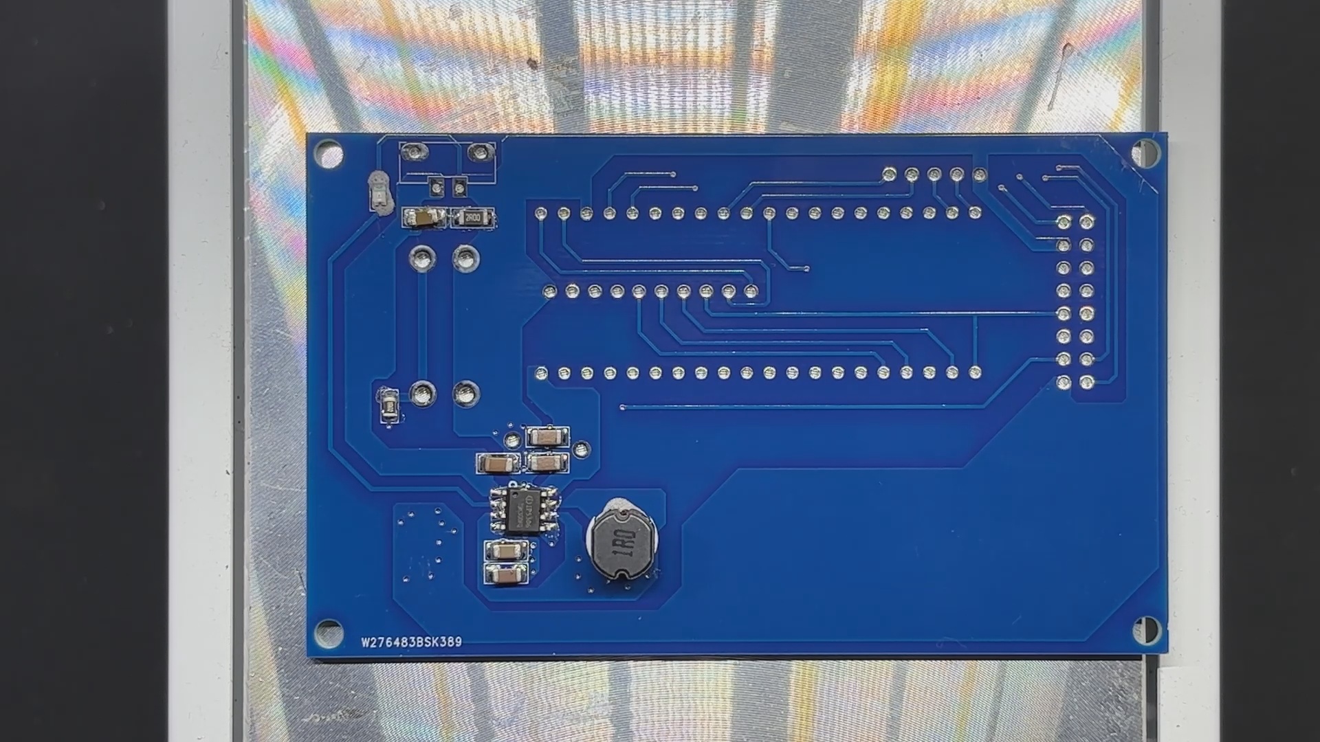
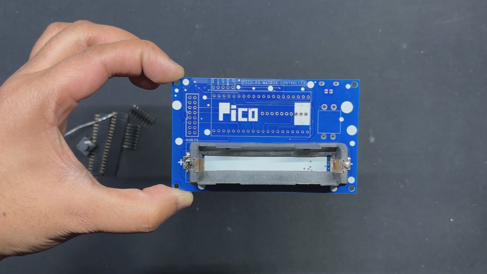
Following the schematic setup, we exported the netlist and created the board file by referring to the CAD file's board layout. The PICO 2, button, lithium cell holder, and USB mini port are all on the top side of the board, while all of the SMD components are on the bottom.
PCB Design: Button Board
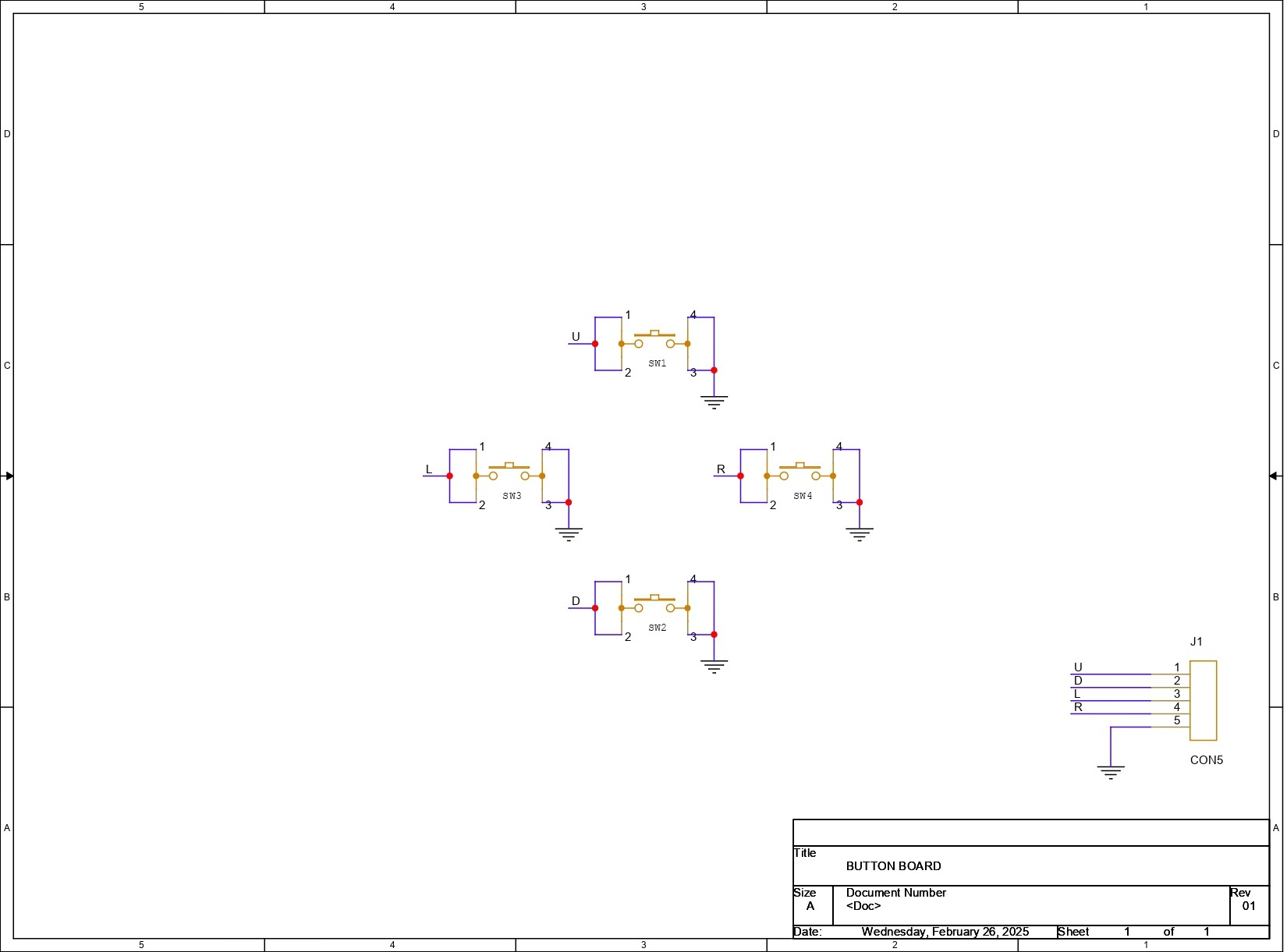
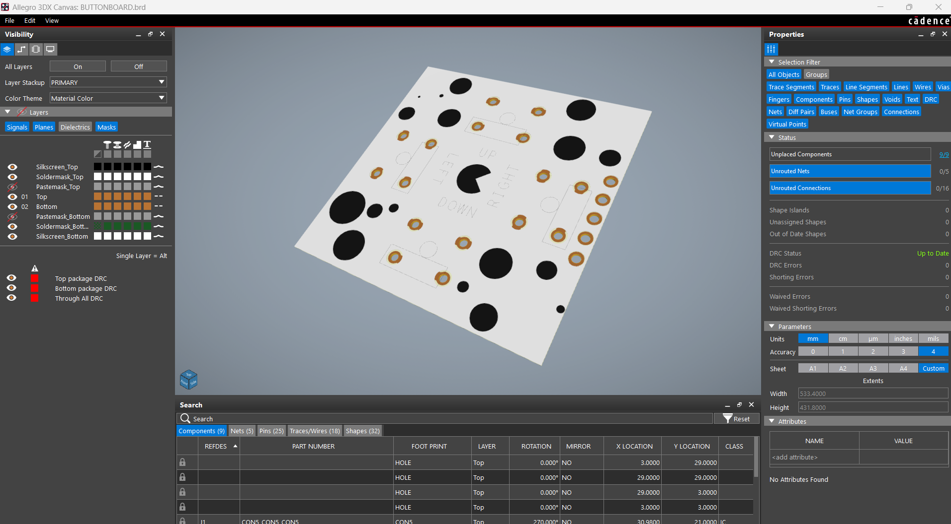
Next, we get the schematic for the button board prepared. It has four push buttons, with the 4 and 3 pins of each button connected to GND. Additionally, there is a CON5 connector that is attached to each connector's 1 and 2 for GPIO and 3 and 4 for GND.
After setting up the schematic, we used the PCB editor to prepare the board file by aligning the buttons in the proper location and following exactly to the CAD file layout.
PCB ASSEMBLY: PICO DRIVER
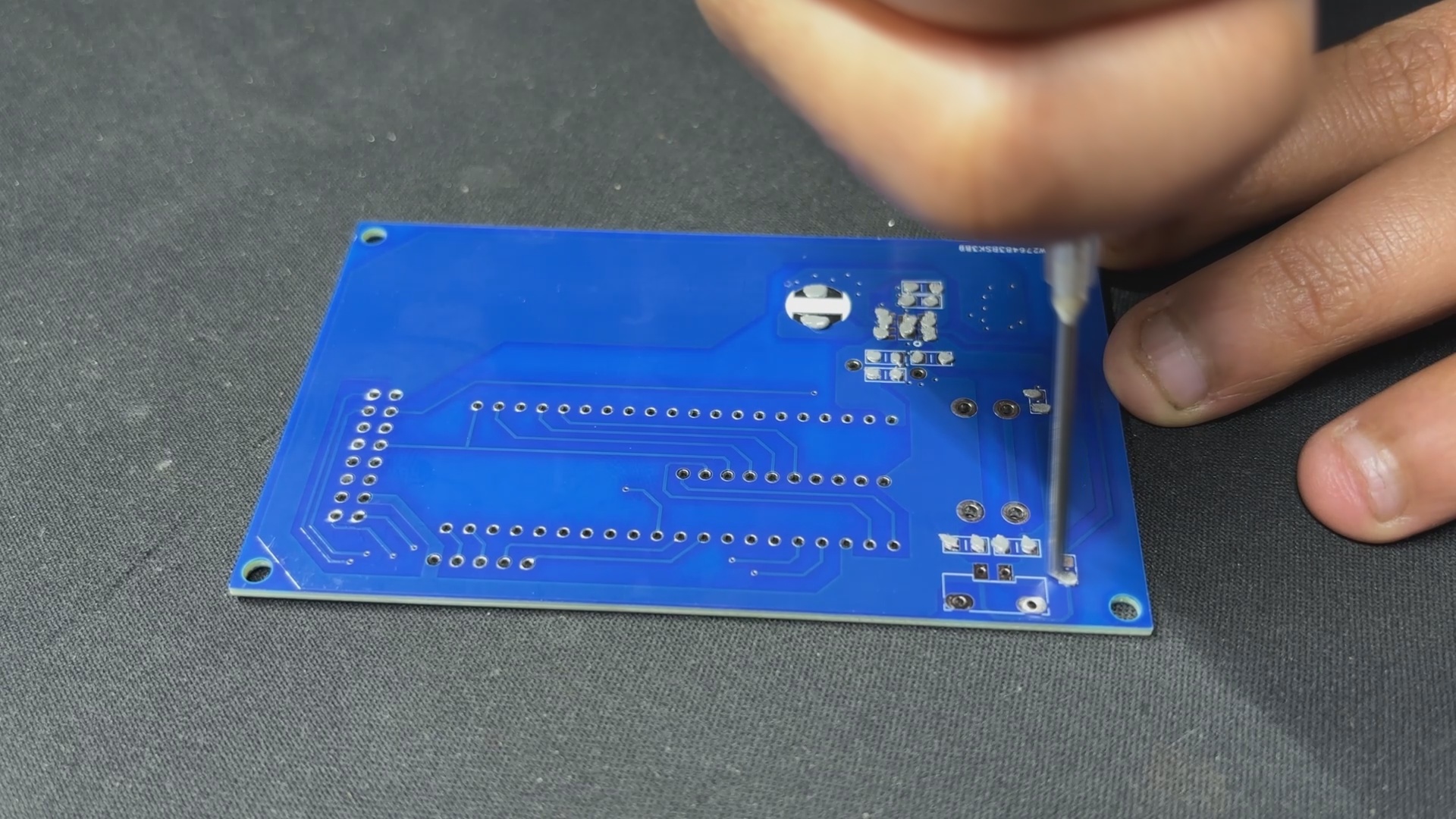

- Using a solderpaste dispencing needle, we apply solderpaste—in this case, 63/37 Sn/Pb solderpaste—on each SMD component PAD to begin the PICO Driver assembly process.
- Next, we use an ESD tweezer to select and position each SMD component on the PCB.
- Following component placement, the circuit is raised and set on the reflow hotplate, which raises the PCB's temperature from below to the melting point of solder paste. Solder paste melts and all SMD components are secure in place when the PCB hits a temperature of 190°C.
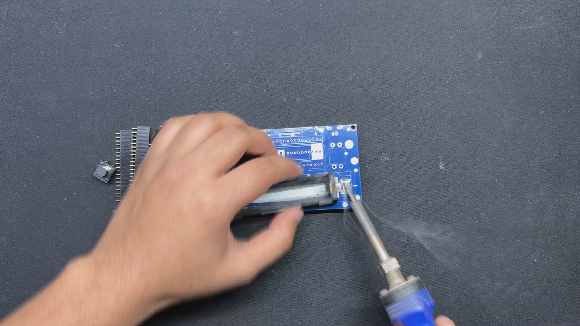
- Following the reflow procedure, we flip the board over and use a soldering iron to position the 18650 Holder.
- After the USB Micro port and Push Switch have been installed, we flip the board over and solder both of their pads.
Testing the Power Section

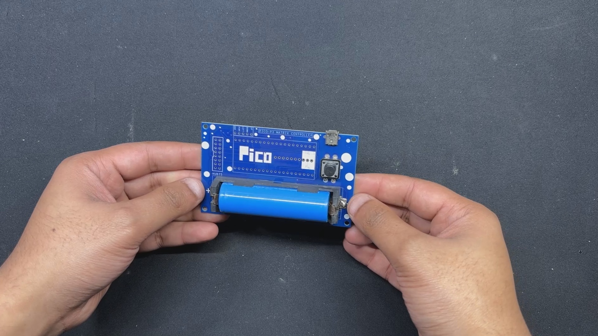
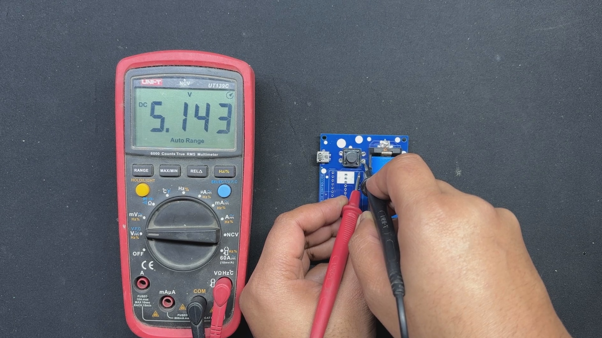
We stop our assembly process and verify the power module circuits by placing the 18650 3.7V 2600mAh lithium cell in its cell holder in the correct polarity before proceeding with the PICO DRIVER assembly process.
The device will then turn on when we press the push button. We use our multimeter to measure the device's output voltage, which should be 5V. We may now add PICO 2 to the PCB and start the assembly process.
PCB ASSEMBLY: PICO DRIVER (Rest of the Assembly)
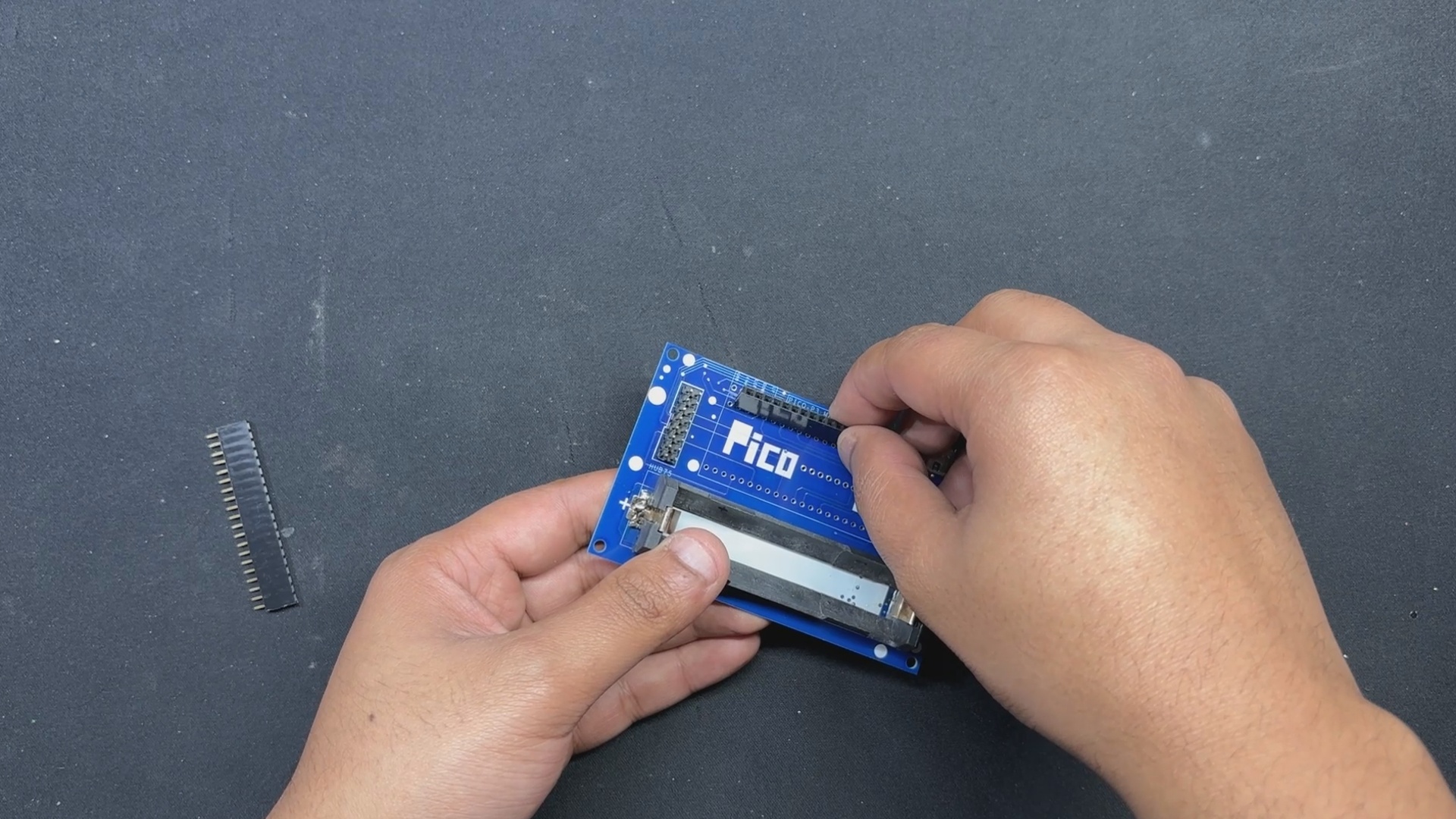
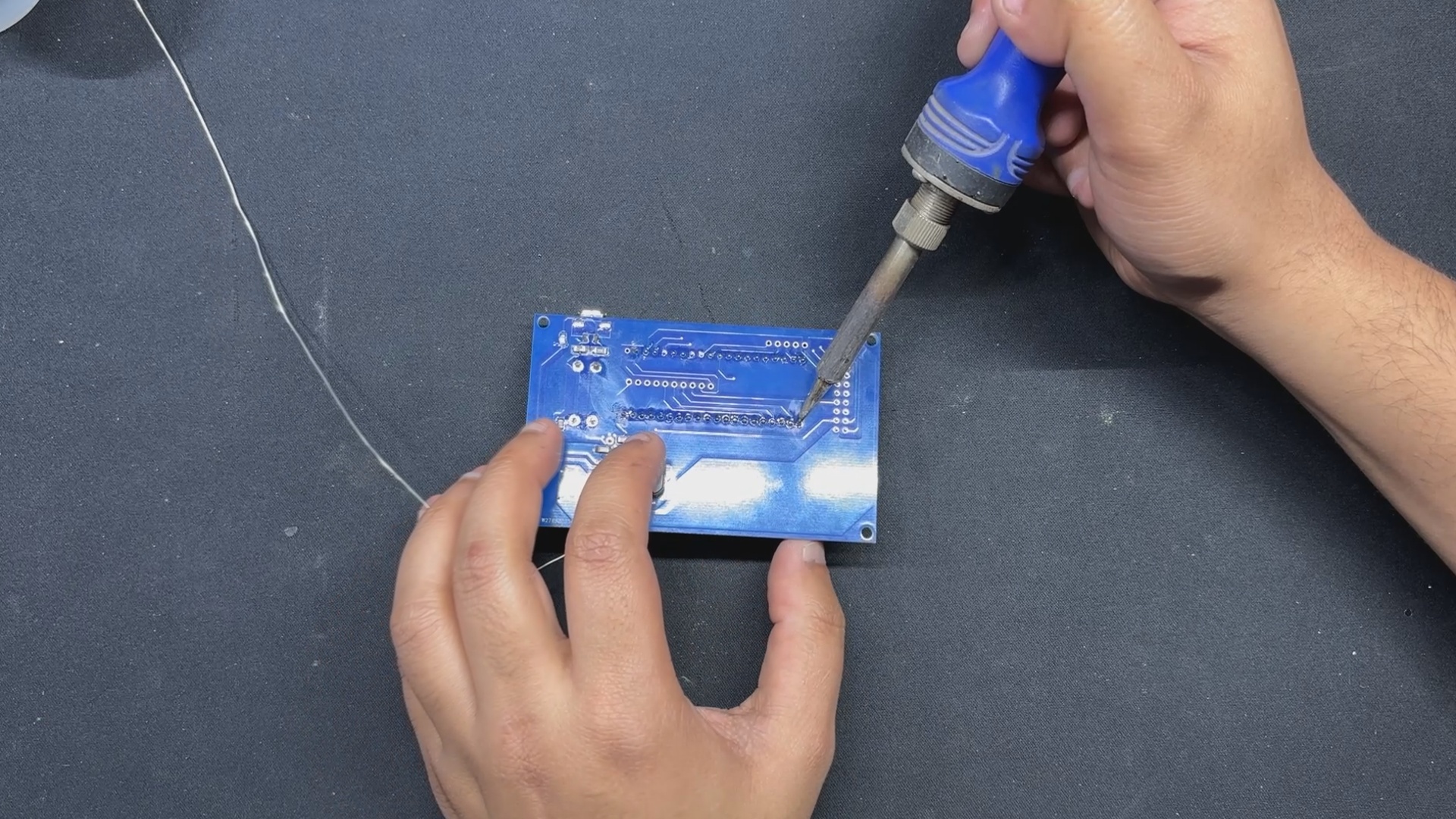


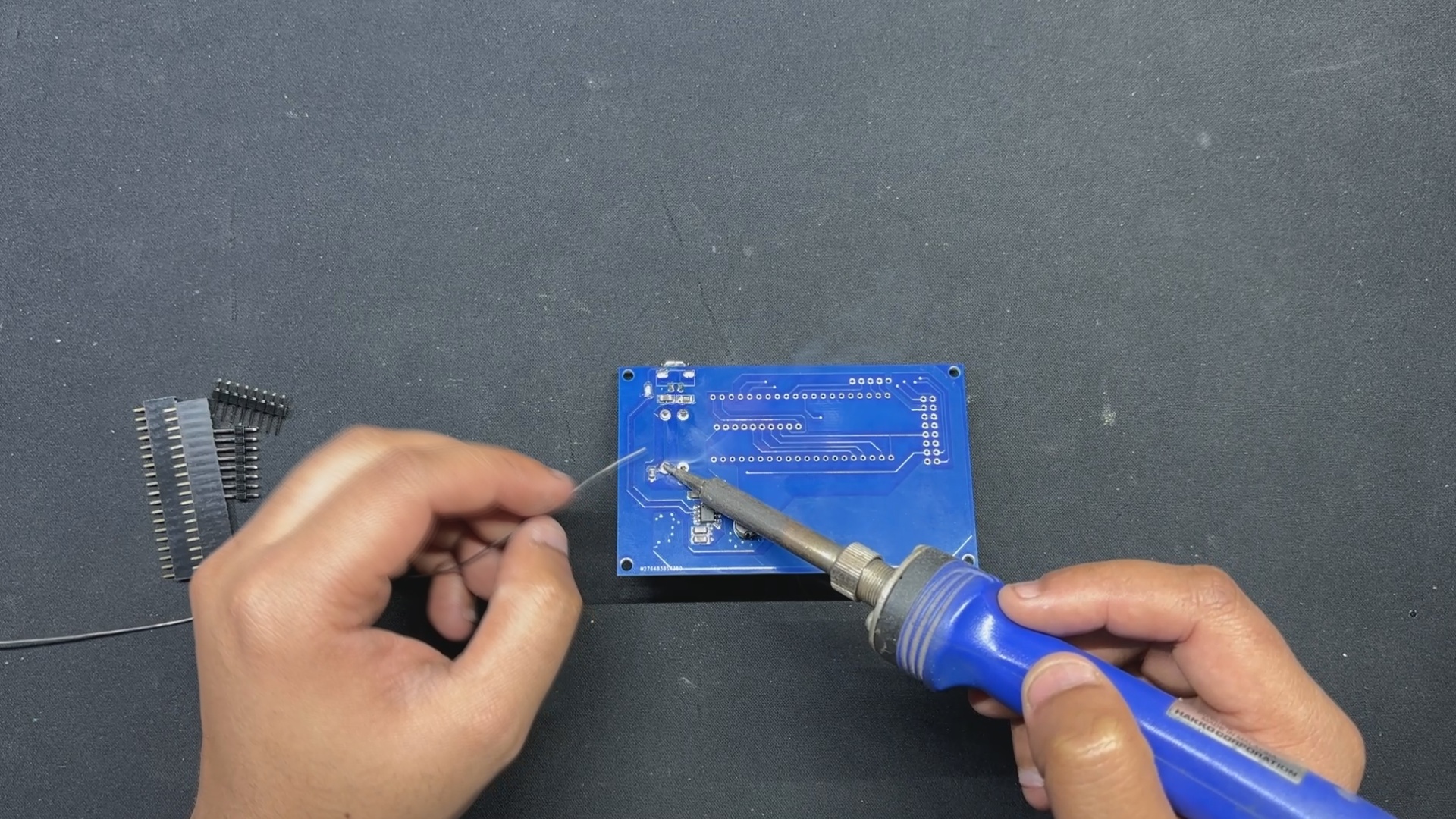
- After positioning two female CON 20 header pins on the PICO 2 footprint and two male CON 8 header pins on the HUB75 connector footprint, we flip the board over and use a soldering iron to solder their pads.
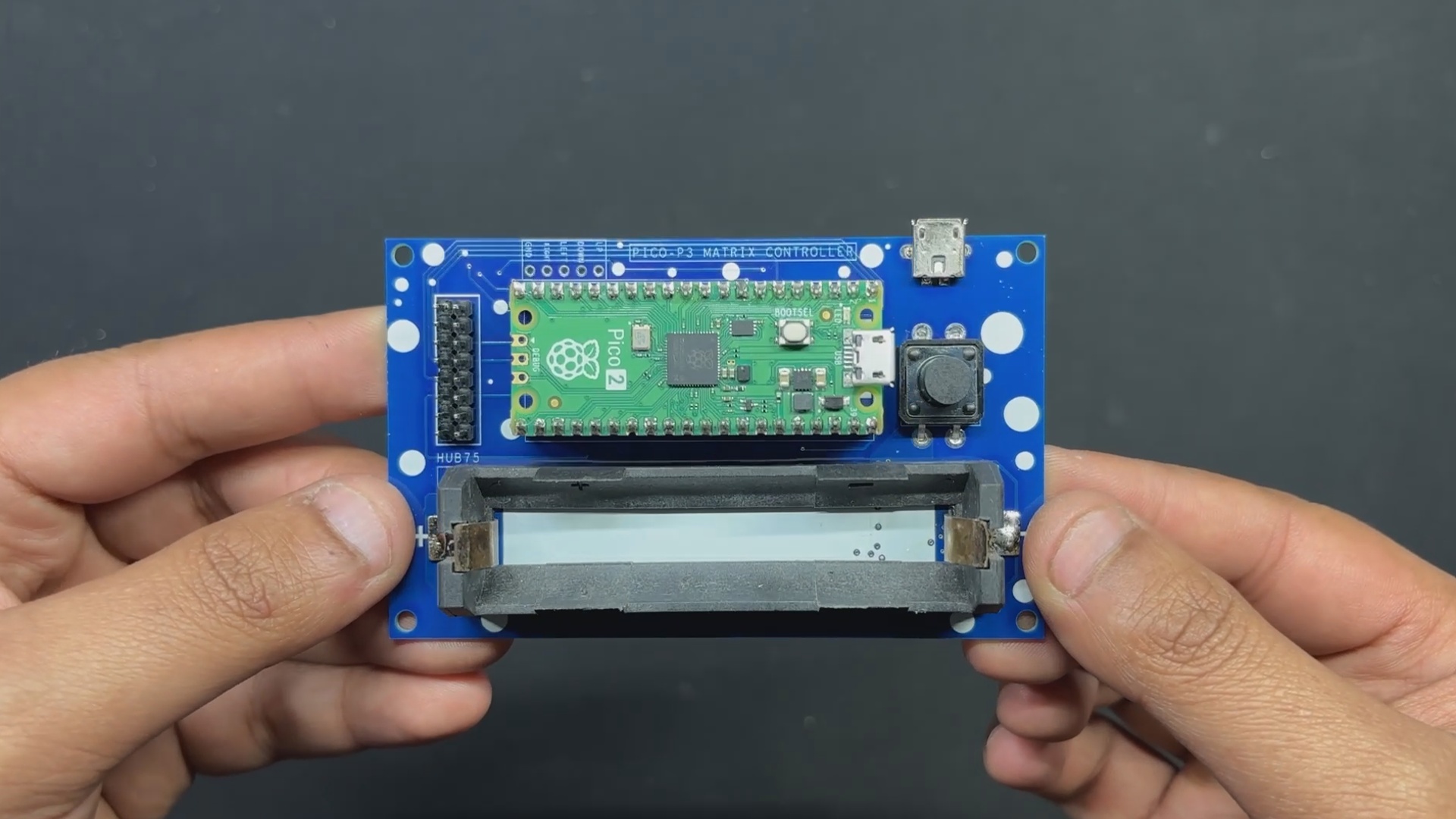
- Finally, we reinstalled the lithium cell in its cell holder and positioned the Raspberry Pi PICO over the CON 20 header pins.
The PICO DRIVER Assembly is completed.
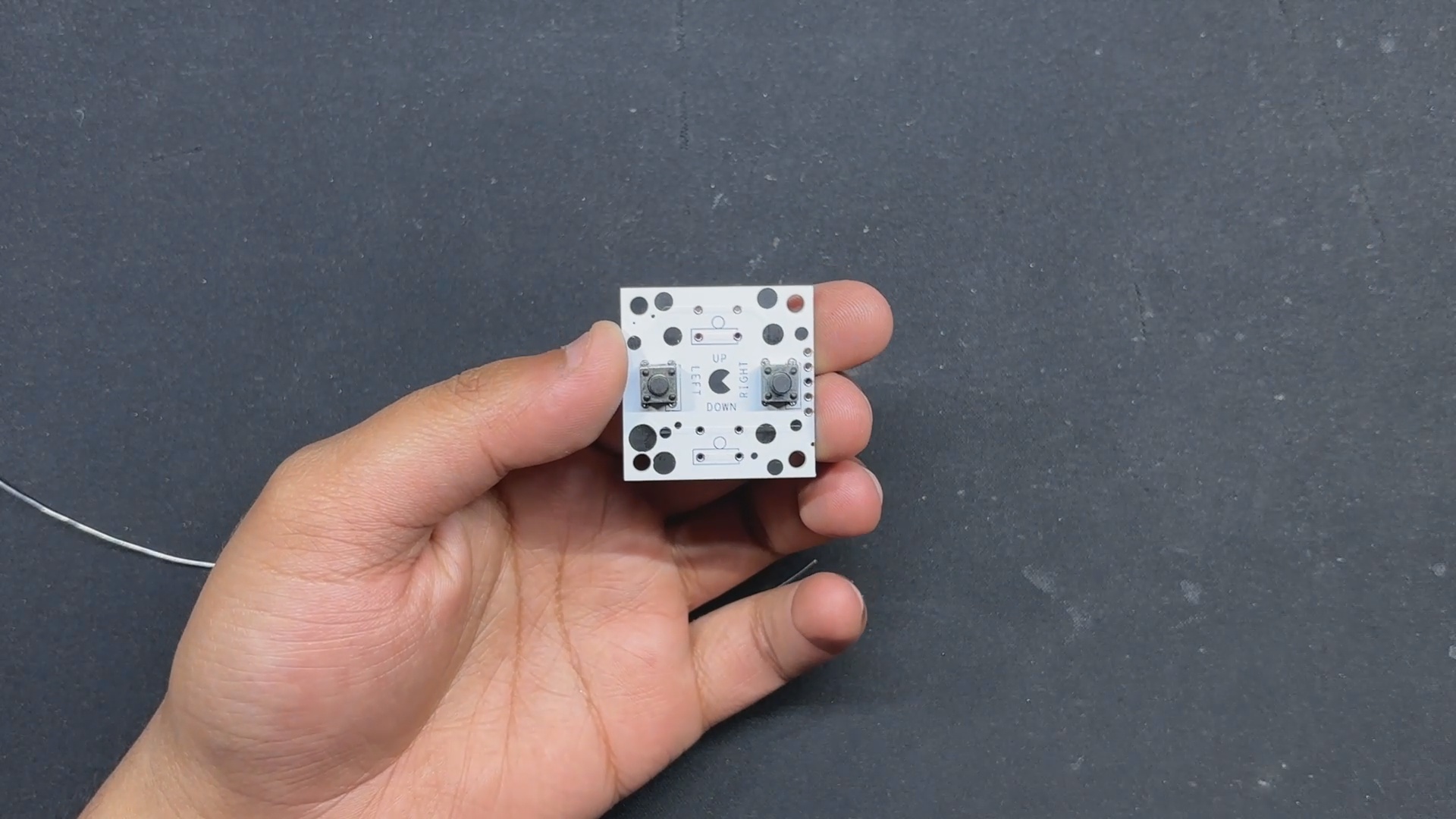
BUTTON BOARD Assembly—D PAD
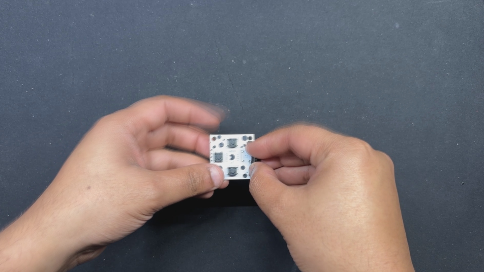
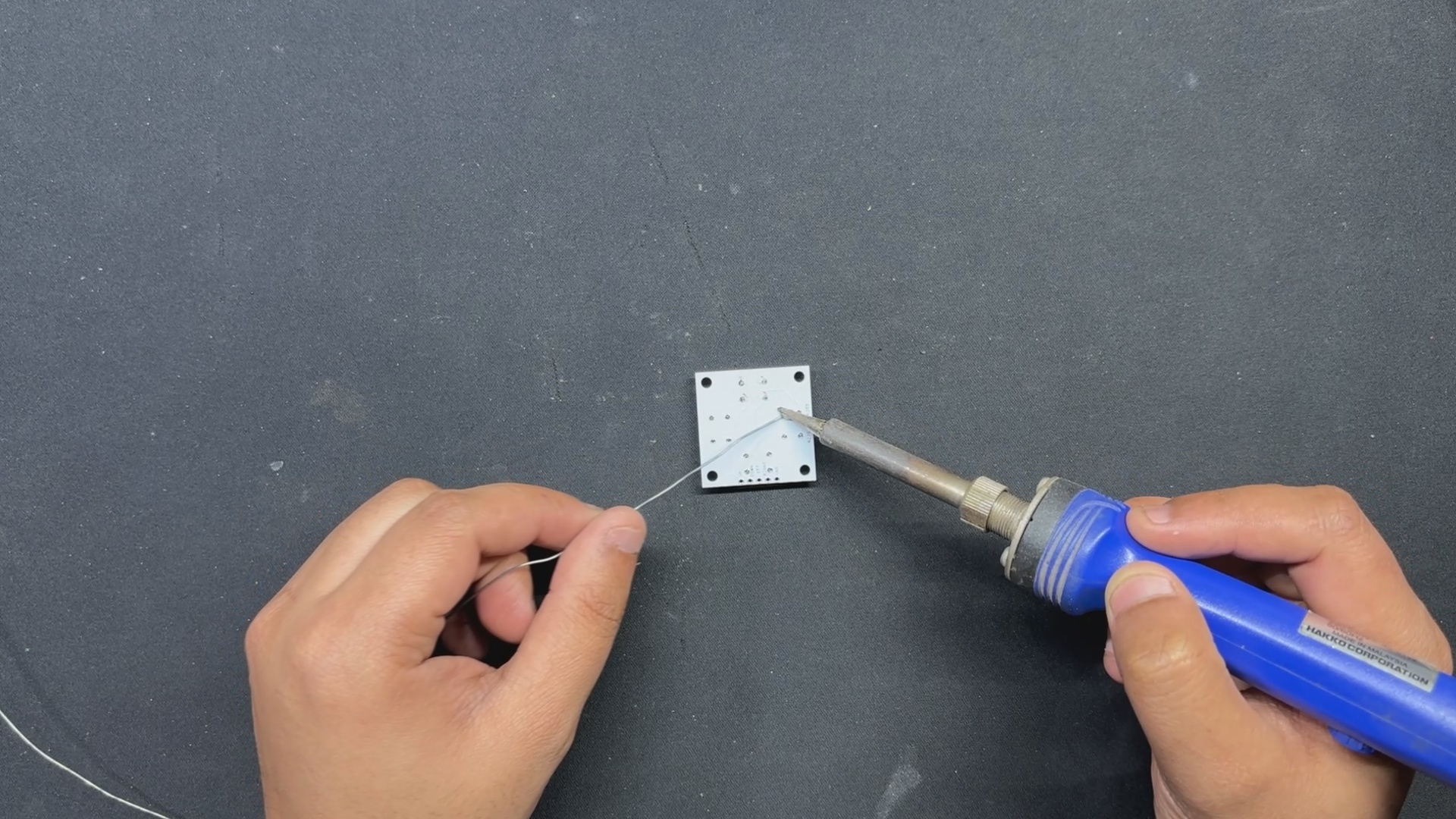
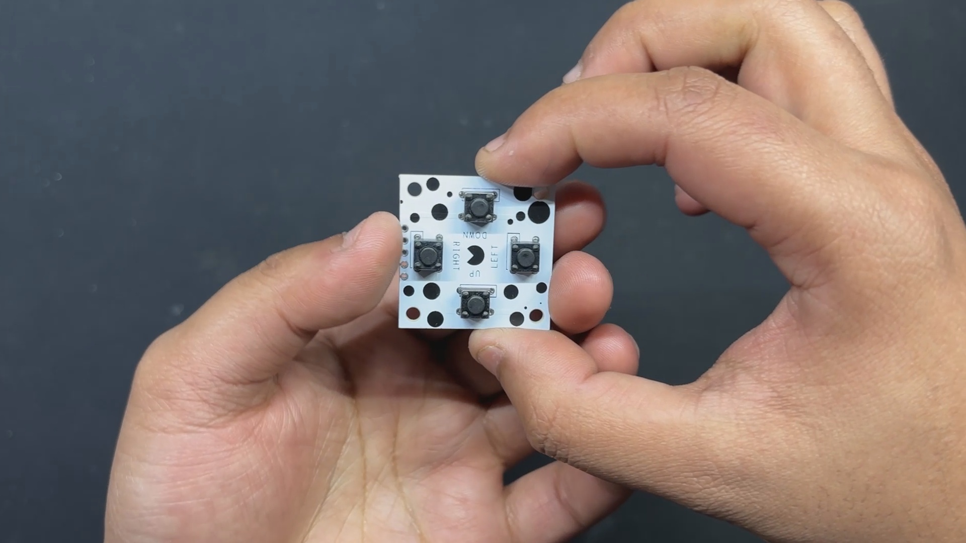
In order to begin the button board assembly process, we first position the four push buttons from the top side of the board, and then we solder their pads from the bottom side.
BUTTON BOARD Assembly- A and B
Similar to the D-PAD Assembly, we place two Push buttons from the top side of the board, and then we solder their pads from the bottom side.
PICO DRIVER and MATRIX ASSEMBLY
- Using the wire harness that was included with the Matrix Kit, we first connect the PICO driver and Matrix. We soldered the positive wire of the wire harness to the 5V output of the PICO DRIVER and the negative wire to the GND of the PICO Driver.
- Next, we attach the female wire harness connector to the matrix's male connector.
- The HUB75 wire harness is then used to connect the matrix and PICO driver GPIOs. It is plugged into the matrix connector first, and then its other end is connected to the PICO driver.
TEST SKETCH: GAME OF LIFE
We connected the Mattrix and PICO DRIVE first, then flashed the PICO using our previously converted Game of Life code that we had taken from an example sketch of the FastLED library to see if our configuration worked.
https://www.instructables.com/64x32-Matrix-Panel-Setup-With-PICO-2/
The remarkable cellular automaton known as the "Game of Life" was developed in 1970 by British mathematician John Horton Conway. Since it is a zero-player game, no extra input is required; rather, the game's progression is determined by its initial state.
Checkout more about game of life from here-
The game will start with a random configuration and restart with a new random configuration after it halts and yes this setup is Turing complete.
#include <Adafruit_Protomatter.h>

// Pin definitions
#define R1 2
#define G1 3
#define B1 4
#define R2 5
#define G2 8
#define B2 9
#define A 10
#define B 16
#define C 18
#define D 20
#define CLK 11
#define LAT 12
#define OE 13

#define WIDTH 64
#define HEIGHT 32

uint8_t rgbPins[] = { R1, G1, B1, R2, G2, B2 };
uint8_t addrPins[] = { A, B, C, D };
Adafruit_Protomatter matrix(WIDTH, HEIGHT, 1, rgbPins, 4, addrPins, CLK, LAT, OE, false);

bool grid[WIDTH][HEIGHT];
bool newGrid[WIDTH][HEIGHT];

void setup() {
  matrix.begin();
  randomSeed(analogRead(0));

  // Initialize grid with random values
  for(int x = 0; x < WIDTH; x++) {
    for(int y = 0; y < HEIGHT; y++) {
      grid[x][y] = random(2);
    }
  }
}

void loop() {
  matrix.fillScreen(0);

  // Update grid based on Game of Life rules
  for(int x = 0; x < WIDTH; x++) {
    for(int y = 0; y < HEIGHT; y++) {
      int aliveNeighbors = countAliveNeighbors(x, y);
      if(grid[x][y]) {
        // Any live cell with two or three live neighbors survives.
        if(aliveNeighbors < 2 || aliveNeighbors > 3) {
          newGrid[x][y] = false;
        } else {
          newGrid[x][y] = true;
        }
      } else {
        // Any dead cell with three live neighbors becomes a live cell.
        if(aliveNeighbors == 3) {
          newGrid[x][y] = true;
        } else {
          newGrid[x][y] = false;
        }
      }
      if(newGrid[x][y]) {
        matrix.drawPixel(x, y, matrix.color565(255, 255, 255)); // White color
      }
    }
  }

  // Copy newGrid to grid
  memcpy(grid, newGrid, sizeof(grid));
  matrix.show();
  delay(100); // Adjust the delay for speed control

  // Check if the grid is stable or empty
  if(isGridStableOrEmpty()) {
    resetGrid();
  }
}

int countAliveNeighbors(int x, int y) {
  int aliveNeighbors = 0;
  for(int dx = -1; dx <= 1; dx++) {
    for(int dy = -1; dy <= 1; dy++) {
      if(dx == 0 && dy == 0) continue;
      int nx = (x + dx + WIDTH) % WIDTH;
      int ny = (y + dy + HEIGHT) % HEIGHT;
      if(grid[nx][ny]) {
        aliveNeighbors++;
      }
    }
  }
  return aliveNeighbors;
}

bool isGridStableOrEmpty() {
  for(int x = 0; x < WIDTH; x++) {
    for(int y = 0; y < HEIGHT; y++) {
      if(grid[x][y]) {
        return false;
      }
    }
  }
  return true;
}

void resetGrid() {
  for(int x = 0; x < WIDTH; x++) {
    for(int y = 0; y < HEIGHT; y++) {
      grid[x][y] = random(2);
    }
  }
}
We are using the Adafruit_Protomatter library here, which you need to install on your Arduino IDE before using this code.
FRAME & MATRIX ASSEMBLY
By aligning the mounting holes of the two 3D-printed handgrip frames with those of the matrix, we can now attach them to the back of the matrix. Six M3 bolts are then used to connect the frame and matrix together. We can easily connect the frame and matrix with an M3 bolt thanks to the M3 brass inserts that have been added to the back of the matrix.
BUTTON BOARD—FRAME ASSEMBLY
First, we install the D Pad Button board over the 3D printed Frame and secure it with four M2 screws. Next, we position the A B button Board and secure it with four M2 screws.
WIRING
- Wiring the DPAD Button PCB and PICO DRIVER board together is the final stage in the assembly process.
- To accomplish this, we first add five connecting wires to the button board's CON5 port, and then we connect each wire to the PICO DRIVER in the correct pin order.
- The button board's UP pin is connected to GPIO7, the DOWN pin to GPIO6, the LEFT pin to GPIO15, and the RIGHT pin to GPIO14.
- For the A B Button PCB, we only need to connect both buttons to GPIO 27 and GPIO 28, with their common Ground connected to GND of PICO 2.
After the wires have been linked, we can enter the main code into our PICO and test the console.
PICO BLASTER GAME CODE
This was the code we prepared for this project, and it's a simple but Long one.
#include <Adafruit_Protomatter.h>
#include <SPI.h>
#include <stdint.h>
#include <math.h>
// Matrix configuration
#define WIDTH 64
#define HEIGHT 32
uint8_t rgbPins[] = {2, 3, 4, 5, 8, 9};
uint8_t addrPins[] = {10, 16, 18, 20};
#define CLK 11
#define LAT 12
#define OE 13
Adafruit_Protomatter matrix(WIDTH, HEIGHT, 1, rgbPins, 4, addrPins, CLK, LAT, OE, false);
// Button pins
#define BUTTON_UP 7
#define BUTTON_DOWN 6
#define BUTTON_LEFT 15
#define BUTTON_RIGHT 14
#define BUTTON_FIRE 27
#define BUTTON_MISSILE 28 // GPIO28 for missile
// Game state variable
bool gameOver = false;
unsigned long gameOverStartTime = 0;
const unsigned long gameOverDuration = 5000; // 5 seconds
// Ship parameters
#define SHIP_WIDTH 7
#define SHIP_HEIGHT 5
int shipX = 0;
int shipY = HEIGHT / 2 - SHIP_HEIGHT / 2;
// Projectile variables
#define PROJECTILE_WIDTH 2
#define PROJECTILE_HEIGHT 2
#define MAX_PROJECTILES 5
int projX[MAX_PROJECTILES];
int projY[MAX_PROJECTILES];
bool projectileActive[MAX_PROJECTILES];
const uint16_t projectileColor = matrix.color565(0, 255, 0);
int nextProjectile = 0;
// Rock variables
#define MAX_ROCKS 5
#define ROCK_SMALL_SIZE 3
#define ROCK_MEDIUM_SIZE 5
#define ROCK_LARGE_SIZE 7
int rocks[MAX_ROCKS][3]; // [x, y, size]
unsigned long lastRockSpawn = 0;
const unsigned long rockSpawnInterval = 500;
const uint16_t rockColor = matrix.color565(255, 100, 0);
const int rockSpeed = 1;
int rockHitCount[MAX_ROCKS];
bool blastActive = false; // Add blast active flag
int blastX, blastY;       // Blast coordinates
unsigned long blastStartTime;
const unsigned long blastDuration = 100; //ms
// Missile variables
#define MISSILE_WIDTH 4
#define MISSILE_HEIGHT 4
int missileX = -1;
int missileY = -1;
bool missileActive = false;
const uint16_t missileColor = matrix.color565(255, 0, 0);
unsigned long lastMissileTime = 0;
const unsigned long missileCooldown = 10000;
// Spaceship sprite data (arrow pointing right)
static const uint8_t shipSprite[SHIP_HEIGHT] = {
0b0010000,
0b0011000,
0b1111111,
0b0011000,
0b0010000
};
const uint16_t shipColor = matrix.color565(0, 255, 255);
// Variables for fire rate control
unsigned long lastFireTime = 0;
const unsigned long fireRate = 200;
// Function to draw a circle
void drawCircle(int x0, int y0, int r, uint16_t color) {
int f = 1 - r;
int ddF_x = 1;
int ddF_y = -2 * r;
int x = 0;
int y = r;
matrix.drawPixel(x0, y0 + r, color);
matrix.drawPixel(x0, y0 - r, color);
matrix.drawPixel(x0 + r, y0, color);
matrix.drawPixel(x0 - r, y0, color);
while (x < y) {
if (f >= 0) {
y--;
ddF_y += 2;
f += ddF_y;
}
x++;
ddF_x += 2;
f += ddF_x;
matrix.drawPixel(x0 + x, y0 + y, color);
matrix.drawPixel(x0 - x, y0 + y, color);
matrix.drawPixel(x0 + x, y0 - y, color);
matrix.drawPixel(x0 - x, y0 - y, color);
matrix.drawPixel(x0 + y, y0 + x, color);
matrix.drawPixel(x0 - y, y0 + x, color);
matrix.drawPixel(x0 + y, y0 - x, color);
matrix.drawPixel(x0 - y, y0 - x, color);
}
}
// Function to draw the blast animation
void drawBlast() {
if (blastActive) {
matrix.drawPixel(blastX, blastY, matrix.color565(255, 255, 255));
matrix.drawPixel(blastX + 1, blastY, matrix.color565(255, 200, 0));
matrix.drawPixel(blastX - 1, blastY, matrix.color565(255, 200, 0));
matrix.drawPixel(blastX, blastY + 1, matrix.color565(255, 200, 0));
matrix.drawPixel(blastX, blastY - 1, matrix.color565(255, 200, 0));
if (millis() - blastStartTime > blastDuration) {
blastActive = false; // Clear the blast after duration
}
}
}
// Function to draw text (using Adafruit_GFX style)
void drawText(int x, int y, const char *text, uint16_t color) {
matrix.setTextColor(color);
matrix.setCursor(x, y);
matrix.print(text);
}
// Function to draw the game over screen
void drawGameOver() {
matrix.fillScreen(0); // Clear the entire screen buffer
// Draw a big circle for the face
int centerX = WIDTH / 2;
int centerY = HEIGHT / 2;
int radius = 10;
uint16_t circleColor = matrix.color565(255, 255, 0); // Yellow
drawCircle(centerX, centerY, radius, circleColor);
// Draw the sad eyes as crosses
uint16_t eyeColor = matrix.color565(0, 0, 0); // Black
matrix.drawPixel(centerX - 5, centerY - 5, eyeColor);
matrix.drawPixel(centerX - 4, centerY - 4, eyeColor);
matrix.drawPixel(centerX - 5, centerY - 4, eyeColor);
matrix.drawPixel(centerX - 4, centerY - 5, eyeColor);
matrix.drawPixel(centerX + 4, centerY - 5, eyeColor);
matrix.drawPixel(centerX + 5, centerY - 4, eyeColor);
matrix.drawPixel(centerX + 4, centerY - 4, eyeColor);
matrix.drawPixel(centerX + 5, centerY - 5, eyeColor);
// Draw the sad mouth
for (int x = centerX - 4; x <= centerX + 4; x++) {
matrix.drawPixel(x, centerY + 3, eyeColor);
}
matrix.show();
}
// Setup function
void setup() {
matrix.begin();
matrix.fillScreen(0);
Serial.begin(9600);
pinMode(BUTTON_UP, INPUT_PULLUP);
pinMode(BUTTON_DOWN, INPUT_PULLUP);
pinMode(BUTTON_LEFT, INPUT_PULLUP);
pinMode(BUTTON_RIGHT, INPUT_PULLUP);
pinMode(BUTTON_FIRE, INPUT_PULLUP);
pinMode(BUTTON_MISSILE, INPUT_PULLUP);
// Initialize rocks
for (int i = 0; i < MAX_ROCKS; i++) {
rocks[i][0] = -ROCK_LARGE_SIZE * 2; // Initialize off-screen
rocks[i][1] = 0;
rocks[i][2] = ROCK_LARGE_SIZE; // Start with largest size
rockHitCount[i] = 0;
}
// Initialize projectiles
for (int i = 0; i < MAX_PROJECTILES; i++) {
projX[i] = -PROJECTILE_WIDTH;
projY[i] = -PROJECTILE_HEIGHT;
projectileActive[i] = false;
}
missileX = -MISSILE_WIDTH;
missileY = -MISSILE_HEIGHT;
missileActive = false;
gameOver = false;
gameOverStartTime = 0; // Initialize
Serial.println("Starting up...");
}
// Function to draw the spaceship
void drawShip() {
if (!gameOver) { // Only draw if game is not over
for (int y = 0; y < SHIP_HEIGHT; y++) {
for (int x = 0; x < SHIP_WIDTH; x++) {
if (bitRead(shipSprite[y], 6 - x)) {
matrix.drawPixel(shipX + x, shipY + y, shipColor);
}
}
}
}
}
// Function to draw the projectiles
void drawProjectiles() {
for (int i = 0; i < MAX_PROJECTILES; i++) {
if (projectileActive[i]) {
matrix.fillRect(projX[i], projY[i], PROJECTILE_WIDTH, PROJECTILE_HEIGHT, projectileColor);
}
}
}
// Function to draw the missile
void drawMissile() {
if (missileActive) {
matrix.fillRect(missileX, missileY, MISSILE_WIDTH, MISSILE_HEIGHT, missileColor);
}
}
// Function to reset the game state
void resetGame() {
gameOver = false;
gameOverStartTime = 0;
shipX = 0;
shipY = HEIGHT / 2 - SHIP_HEIGHT / 2;
for (int i = 0; i < MAX_PROJECTILES; i++) {
projX[i] = -PROJECTILE_WIDTH;
projY[i] = -PROJECTILE_HEIGHT;
projectileActive[i] = false;
}
for (int i = 0; i < MAX_ROCKS; i++) {
rocks[i][0] = -ROCK_LARGE_SIZE * 2; // Reset all rocks offscreen
rocks[i][1] = 0;
rocks[i][2] = ROCK_LARGE_SIZE;
rockHitCount[i] = 0;
}
missileX = -MISSILE_WIDTH;
missileY = -MISSILE_HEIGHT;
missileActive = false;
lastRockSpawn = 0;
lastFireTime = 0;
lastMissileTime = 0;
blastActive = false;
}
// Main loop
void loop() {
if (gameOver) {
drawGameOver();
if (millis() - gameOverStartTime >= gameOverDuration) {
resetGame();
}
return; // Stop updating the game
}
matrix.fillScreen(0);
// Movement handling
if (!digitalRead(BUTTON_UP)) {
shipY = max(shipY - 1, 0);
}
if (!digitalRead(BUTTON_DOWN)) {
shipY = min(shipY + 1, HEIGHT - SHIP_HEIGHT); // Corrected variable name here
}
if (!digitalRead(BUTTON_LEFT)) {
shipX = max(shipX - 1, 0);
}
if (!digitalRead(BUTTON_RIGHT)) {
shipX = min(shipX + 1, WIDTH - SHIP_WIDTH);
}
// Firing projectiles
if (!digitalRead(BUTTON_FIRE) && (millis() - lastFireTime >= fireRate)) {
int projectileIndex = -1;
for (int i = 0; i < MAX_PROJECTILES; i++) {
if (!projectileActive[i]) {
projectileIndex = i;
break;
}
}
if (projectileIndex != -1) {
projX[projectileIndex] = shipX + SHIP_WIDTH;
projY[projectileIndex] = shipY + SHIP_HEIGHT / 2 - PROJECTILE_HEIGHT / 2;
projectileActive[projectileIndex] = true;
lastFireTime = millis();
Serial.println("Fire!");
}
}
// Fire Missile
if (!digitalRead(BUTTON_MISSILE) && (millis() - lastMissileTime >= missileCooldown) && !missileActive) {
missileX = shipX + SHIP_WIDTH;
missileY = shipY + SHIP_HEIGHT / 2 - MISSILE_HEIGHT / 2;
missileActive = true;
lastMissileTime = millis();
Serial.println("Missile Fire!");
}
// Projectile movement
for (int i = 0; i < MAX_PROJECTILES; i++) {
if (projectileActive[i]) {
projX[i] += 3;
if (projX[i] >= WIDTH) {
projectileActive[i] = false;
projX[i] = -PROJECTILE_WIDTH;
projY[i] = -PROJECTILE_HEIGHT;
}
}
}
// Missile movement
if (missileActive) {
missileX += 2;
if (missileX >= WIDTH) {
missileActive = false;
missileX = -MISSILE_WIDTH;
missileY = -MISSILE_HEIGHT;
}
}
// Rock spawning
if (millis() - lastRockSpawn > rockSpawnInterval) {
int availableRockSlot = -1;
for (int i = 0; i < MAX_ROCKS; i++) {
if (rocks[i][0] <= -ROCK_LARGE_SIZE * 2) { // Check if rock is off-screen
availableRockSlot = i;
break;
}
}
if (availableRockSlot != -1) {
rocks[availableRockSlot][0] = WIDTH;
rocks[availableRockSlot][1] = random(HEIGHT - ROCK_LARGE_SIZE * 2 + 1) + ROCK_LARGE_SIZE;
rocks[availableRockSlot][2] = random(3) == 0 ? ROCK_SMALL_SIZE : (random(2) == 0 ? ROCK_MEDIUM_SIZE : ROCK_LARGE_SIZE); // Random size
lastRockSpawn = millis();
}
}
// Rock handling and collision
for (int i = 0; i < MAX_ROCKS; i++) {
if (rocks[i][0] >= 0) {
rocks[i][0] -= rockSpeed;
int rockSize = rocks[i][2];
uint16_t drawColor = rockColor;
if (rockSize == ROCK_SMALL_SIZE) {
drawColor = matrix.color565(255, 140, 0); // Darker Orange #FF8C00
} else if (rockSize == ROCK_MEDIUM_SIZE) {
drawColor = matrix.color565(255,255,0); // Yellow
} else {
drawColor = matrix.color565(255, 0, 0); // Red
}
drawCircle(rocks[i][0], rocks[i][1], rockSize, drawColor);
// Game over check
if (shipX < rocks[i][0] + rockSize &&
shipX + SHIP_WIDTH > rocks[i][0] - rockSize &&
shipY < rocks[i][1] + rockSize &&
shipY + SHIP_HEIGHT > rocks[i][1] - rockSize) {
gameOver = true;
gameOverStartTime = millis(); // Record start time
Serial.println("Game Over - Ship hit by rock!");
break; // Exit the loop
}
// Check collision with projectiles
for (int j = 0; j < MAX_PROJECTILES; j++) {
if (projectileActive[j] &&
projX[j] < rocks[i][0] + rockSize &&
projX[j] + PROJECTILE_WIDTH > rocks[i][0] - rockSize &&
projY[j] < rocks[i][1] + rockSize &&
projY[j] + PROJECTILE_HEIGHT > rocks[i][1] - rockSize) {
rockHitCount[i]++;
projectileActive[j] = false;
projX[j] = -PROJECTILE_WIDTH;
projY[j] = -PROJECTILE_HEIGHT;
Serial.println("Hit Rock!");
if ((rocks[i][2] == ROCK_SMALL_SIZE && rockHitCount[i] >= 1) ||
(rocks[i][2] == ROCK_MEDIUM_SIZE && rockHitCount[i] >= 2) ||
(rocks[i][2] == ROCK_LARGE_SIZE && rockHitCount[i] >= 3)) { // 3 hits for large
rocks[i][0] = -ROCK_LARGE_SIZE * 2;
rockHitCount[i] = 0;
blastX = rocks[i][0]; // Store blast coordinates
blastY = rocks[i][1];
blastActive = true;    // Trigger blast
blastStartTime = millis();
}
break;
}
}
// Check collision with missile
if (missileActive &&
missileX < rocks[i][0] + rockSize &&
missileX + MISSILE_WIDTH > rocks[i][0] - rockSize &&
missileY < rocks[i][1] + rockSize &&
missileY + MISSILE_HEIGHT > rocks[i][1] - rockSize) {
rocks[i][0] = -ROCK_LARGE_SIZE * 2;
rockHitCount[i] = 0;
missileActive = false;
missileX = -MISSILE_WIDTH;
missileY = -MISSILE_HEIGHT;
Serial.println("Missile Hit Rock!");
blastX = rocks[i][0]; // Store blast coordinates
blastY = rocks[i][1];
blastActive = true;    // Trigger blast
blastStartTime = millis();
}
}
}
drawShip();
drawProjectiles();
drawMissile();
drawBlast(); // Draw blast
matrix.show();
delay(50);
}
Setup for the LED Matrix Display
#define WIDTH 64
#define HEIGHT 32
uint8_t rgbPins[] = {2, 3, 4, 5, 8, 9};
uint8_t addrPins[] = {10, 16, 18, 20};
#define CLK 11
#define LAT 12
#define OE 13

Adafruit_Protomatter matrix(WIDTH, HEIGHT, 1, rgbPins, 4, addrPins, CLK, LAT, OE, false);
This Section Configures pins to control the 64x32 RGB LED matrix. the Adafruit_Protomatter initializes the matrix library for displaying pixels, text, or graphics and Control pins (CLK, LAT, OE) handle data timing and refresh rates.
Spaceship Setup
#define SHIP_WIDTH 7
#define SHIP_HEIGHT 5
int shipX = 0;
int shipY = HEIGHT / 2 - SHIP_HEIGHT / 2;
This Section Defines the spaceship's size and starting position (shipX, shipY) on the screen. Initially, the ship is centered vertically.
static const uint8_t shipSprite[SHIP_HEIGHT] = {
    0b0010000,
    0b0011000,
    0b1111111,
    0b0011000,
    0b0010000
};
This is a binary representation of the spaceship sprite. Each row represents one horizontal layer of the ship (an arrow-like shape pointing right).
Projectile Handling
#define PROJECTILE_WIDTH 2
#define PROJECTILE_HEIGHT 2
#define MAX_PROJECTILES 5
int projX[MAX_PROJECTILES];
int projY[MAX_PROJECTILES];
bool projectileActive[MAX_PROJECTILES];
const uint16_t projectileColor = matrix.color565(0, 255, 0);
int nextProjectile = 0;
This Sets up an array to track projectiles' positions and activation state (projX, projY, projectileActive) and Defines a maximum of 5 active projectiles (MAX_PROJECTILES)
Firing Logic
if (!digitalRead(BUTTON_FIRE) && (millis() - lastFireTime >= fireRate)) {
    int projectileIndex = -1;
    for (int i = 0; i < MAX_PROJECTILES; i++) {
        if (!projectileActive[i]) {
            projectileIndex = i;
            break;
        }
    }
    if (projectileIndex != -1) {
        projX[projectileIndex] = shipX + SHIP_WIDTH;
        projY[projectileIndex] = shipY + SHIP_HEIGHT / 2 - PROJECTILE_HEIGHT / 2;
        projectileActive[projectileIndex] = true;
        lastFireTime = millis();
        Serial.println("Fire!");
    }
}
This Section Checks button input (BUTTON_FIRE) and ensures firing respects the cooldown (fireRate) and then Activates the next available projectile and positions it to fire from the center-right of the ship.
Missile Initialization
#define MISSILE_WIDTH 4
#define MISSILE_HEIGHT 4
int missileX = -1;
int missileY = -1;
bool missileActive = false;
const uint16_t missileColor = matrix.color565(255, 0, 0);
unsigned long lastMissileTime = 0;
const unsigned long missileCooldown = 10000;
This part Creates variables for missile position and activity. Initially, the missile is inactive (missileActive = false).
It also sets a longer cooldown compared to projectiles (missileCooldown = 10 seconds).
Missile Firing
if (!digitalRead(BUTTON_MISSILE) && (millis() - lastMissileTime >= missileCooldown) && !missileActive) {
    missileX = shipX + SHIP_WIDTH;
    missileY = shipY + SHIP_HEIGHT / 2 - MISSILE_HEIGHT / 2;
    missileActive = true;
    lastMissileTime = millis();
    Serial.println("Missile Fire!");
}
This Fires a missile with a cooldown. The missile starts from the center-right edge of the ship.
Rock Initialization (Obstacle)
#define MAX_ROCKS 5
#define ROCK_SMALL_SIZE 3
#define ROCK_MEDIUM_SIZE 5
#define ROCK_LARGE_SIZE 7
int rocks[MAX_ROCKS][3]; // [x, y, size]
unsigned long lastRockSpawn = 0;
const unsigned long rockSpawnInterval = 500;
const uint16_t rockColor = matrix.color565(255, 100, 0);
const int rockSpeed = 1;
This part Sets up rock attributes: position (rocks[i][0], rocks[i][1]), size (rocks[i][2]), and movement speed (rockSpeed = 1). Also, Rocks spawn every 500ms.
Rock Movement
for (int i = 0; i < MAX_ROCKS; i++) {
    if (rocks[i][0] >= 0) {
        rocks[i][0] -= rockSpeed;
    }
}
This part Moves rocks leftward by subtracting their position (rocks[i][0] -= rockSpeed). Rocks off-screen are reset for reuse.
Collision Detection—Projectile vs Rock
if (projectileActive[j] &&
    projX[j] < rocks[i][0] + rockSize &&
    projX[j] + PROJECTILE_WIDTH > rocks[i][0] - rockSize &&
    projY[j] < rocks[i][1] + rockSize &&
    projY[j] + PROJECTILE_HEIGHT > rocks[i][1] - rockSize) {
        rockHitCount[i]++;
        projectileActive[j] = false;
        projX[j] = -PROJECTILE_WIDTH;
        projY[j] = -PROJECTILE_HEIGHT;
        Serial.println("Hit Rock!");
}
This Checks if a projectile intersects a rock. If true:
- Marks the projectile inactive.
- Tracks the number of hits the rock has taken.
Game Over Logic - When Ship Collides
if (shipX < rocks[i][0] + rockSize &&
    shipX + SHIP_WIDTH > rocks[i][0] - rockSize &&
    shipY < rocks[i][1] + rockSize &&
    shipY + SHIP_HEIGHT > rocks[i][1] - rockSize) {
    gameOver = true;
    gameOverStartTime = millis();
    Serial.println("Game Over - Ship hit by rock!");
}
This section ends the game when the ship collides with a rock and then displays the "Game Over" screen.
RESULT
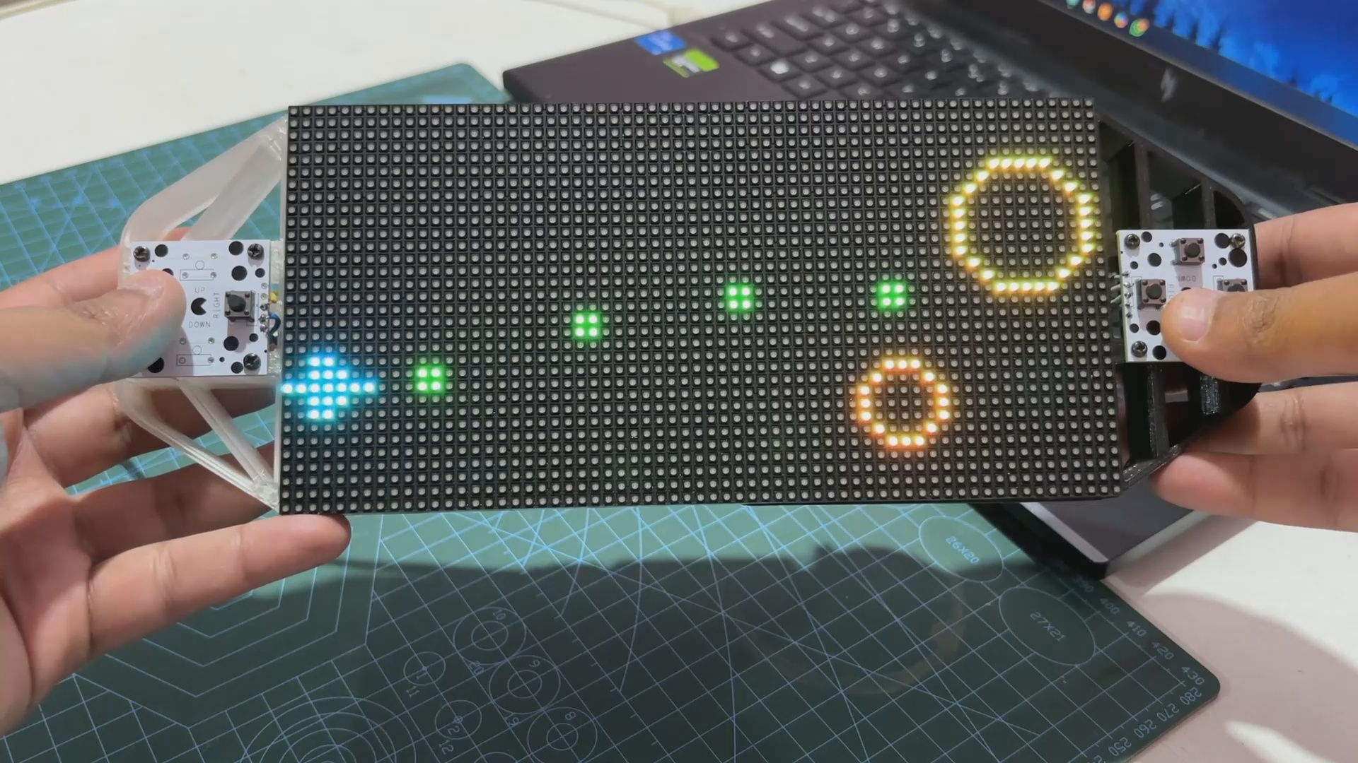
Here's the end result of this simple build: a working same invaders game that we built from scratch running on our CUSTOM GAME CONSOLE, which was also built from the ground up. The entire system is a DIY game console setup that can currently play two games: Snake and this new PICO BLASTER.
We can maneuver our spacecraft up, down, left, and right using the Direction Buttons, and we can fire bullets or blasts using the Weapon Buttons.
The screen refresh rate is super smooth and PICO 2 is handling this task quite well. If our spacecraft hits any projectile, we are greeted with a game over screen that shows a whole yellow circle showing that the circles WON. this splash screen stays for 5 seconds, and then the whole game resets.
This game is currently very basic and made up of simple geometrical shapes. We may further change this code by adding sprites to the game file, which are created using a pixel art generator and then turned into .H files. We can add more adversaries and objects to our game to improve its overall functionality.
Reach out to me if you require any extra assistance.
This game code, as well as the build instructions for this project or the snake game console, are accessible in this article, and it was previously published, so feel free to tweak the code and create your own game console.
Thanks for reaching this far, and I will be back with a new project pretty soon.
Peace.