Currency
Toggle Nav

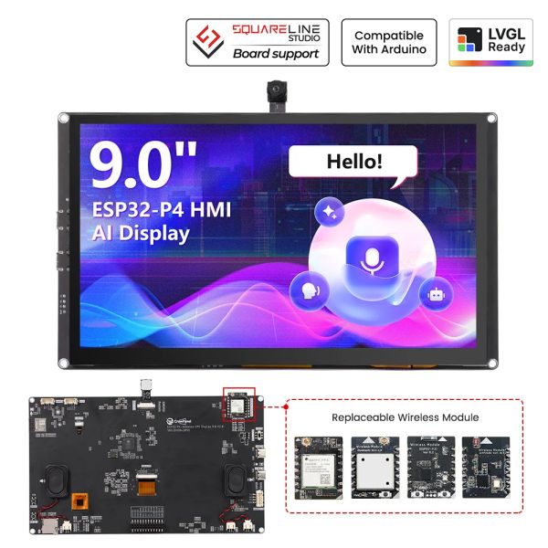


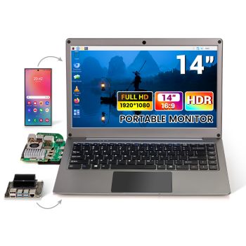
CrowPanel Advanced 9inch |ESP32-P4 HMI AI Display 1024x600 IPS Touch Screen | WiFi 6 Support |Compatible with Arduino/LVGL
As low as
$50.90
Availability:
In stock
Only %1 left
SKU
DHE04209D
Brand
elecrow
Weight
700g
Related Products:


[ESP32 HMI 9-inch display] ESP32-P4 RISC-V architecture, large memory configuration, and powerful performance;
[Dedicated wireless connectivity] EDedicated ESP32-C6 module, Wi-Fi 6 + Bluetooth 5.3, stable and low-power;
[9-inch HD IPS screen] 1024*600 resolution, IPS capacitive touchscreen, and multi-touch support;
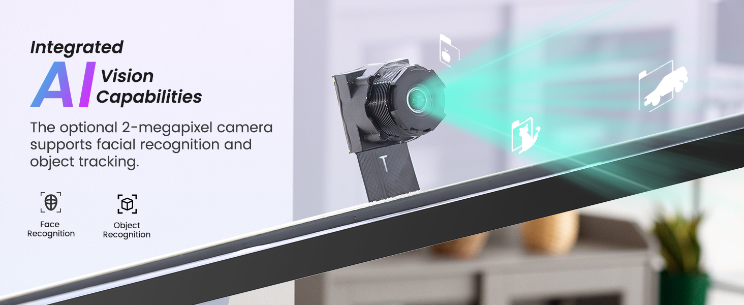
[Integrated AI vision capabilities] Optional 2-megapixel camera supports facial recognition and object tracking.
[Fully functional expansion interfaces] Dual Type-C, 11pin GPIO, UART/I2C, and other interfaces support flexible external connections.
[Interchangeable wireless modules] Supports Wi-Fi 6, Zigbee, WiFi Halow, and other wireless modules, allowing for easy switching between multiple protocols.
[AI acceleration] Powerful computing power supports machine learning and real-time analysis, suitable for high-performance scenarios such as smart home appliances and industrial control.
Note: The ESP32 P4 Official is not supported by the PlatformIO platform.
Frequently Bought Together


CrowPanel Advanced 9" ESP32-P4 Flagship HMI Display
The CrowPanel Advance ESP32-P4 HMI series is a high-performance AI-powered intelligent interactive terminal designed for demanding applications. It employs an innovative dual-chip architecture, combining powerful computing capabilities, rich multimedia functions, and extreme scalability, making it the ideal core for driving next-generation intelligent devices.
This 9-inch screen is powered by the RISC-V-based ESP32-P4 SoC, featuring high-performance and low-power cores operating at frequencies up to 400MHz. Combined with 16MB of Flash and 32MB of PSRAM, it provides ample power for complex graphical interfaces and real-time AI tasks.
The onboard ESP32-C6-MINI-1 module supports 2.4GHz Wi-Fi 6 and Bluetooth 5.3, ensuring stable and reliable connectivity and excellent power consumption control.
The 9inch IPS touchscreen integrates capacitive touch technology and has a resolution of 1024*600, providing users with an intuitive interactive experience. Integrated with a 2MP MIPI-CSI camera (optional), it not only supports high-definition image acquisition but also efficiently runs edge AI applications, such as real-time face recognition and dynamic target tracking.
Professional audio system. Onboard NS4168 audio codec and single microphone array provide high-fidelity playback and accurate far-field speech recognition capabilities. A dual-channel speaker laying a solid foundation for voice interaction and suitable for voice assistants, smart home control, and other scenarios
The 9-inch screen also boasts exceptional expandability. Equipped with dual USB-C ports (UART adapter/USB 2.0 Device), 11pin GPIO, multiple Crowtail interfaces (supporting I2C/UART protocols), and a replaceable wireless module slot (supporting Thread, Zigbee, Halow, etc.), it easily adapts to various sensors and communication protocols.
Why choose the P4 HMI series?
Compared to previous generations(Basic/Advanced ESP32-S3), the ESP32-P4 HMI series achieves a significant leap in machine learning inference and real-time data processing performance through an upgraded processor and AI instruction set. Whether it's a smart home central control, an industrial control panel, a commercial display device, or an AIoT application in Industry 4.0, its comprehensive peripheral support can provide excellent solutions to help you quickly build powerful and interactive smart products.
Quick Click to where you are interested: #Feature, #Specification, #Wireless Module Details, #Documents, #Review
Note: The ESP32 P4 Official is not supported by the PlatformIO platform.
Designed & manufactured by Elecrow, customized requests can be discussed(based on MOQ), you can contact us at service@elecrow.com.
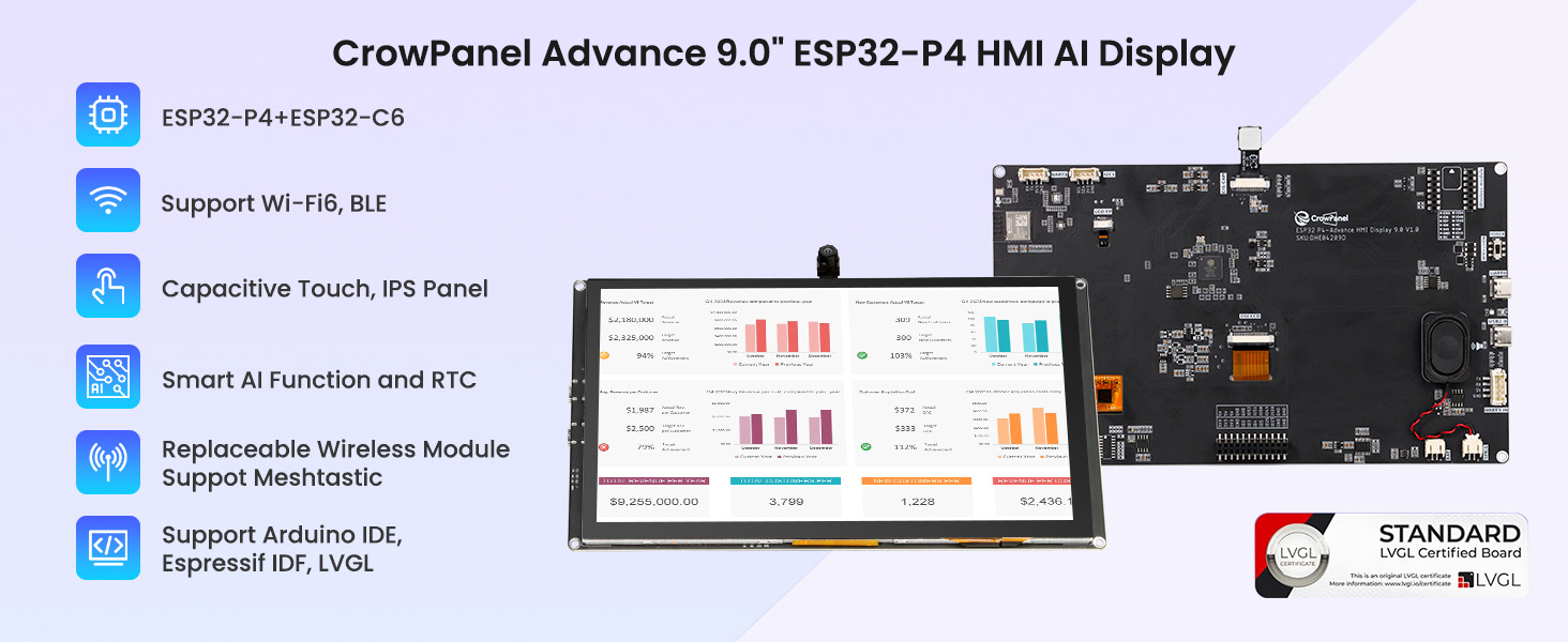
ESP32-P4+ ESP32-C6 dual chips

Integrated Intelligent AI Functions
Voice interaction is achieved through the microphone and speaker, allowing seamless conversations with the smart assistant and easy access to information. 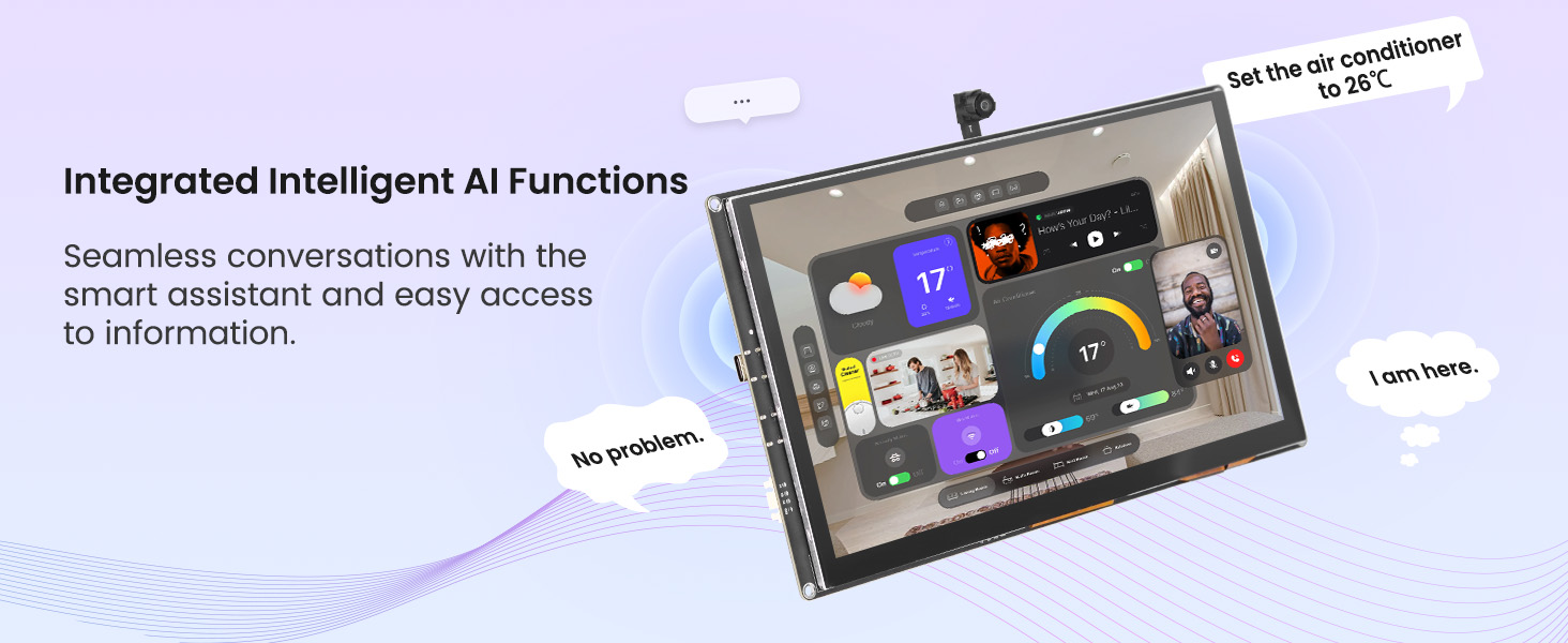
The optional Camera provides AI Vision capabilities
Replaceable Wireless module design, easy to replace multiple protocols

Human-Machine Interface

Support the LVGL development

Support multiple development environments

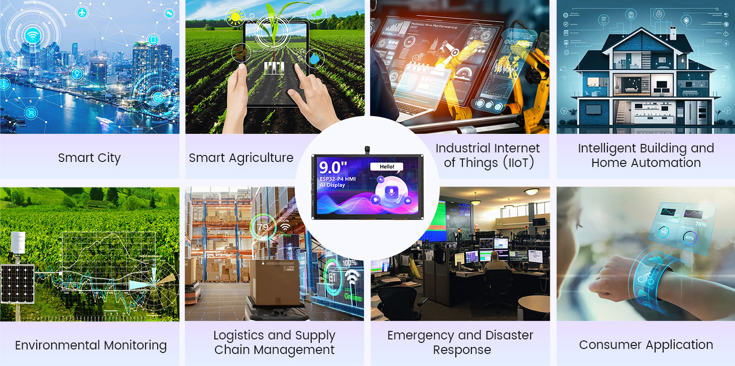
Application Scenario

Feature
✅ Powerful dual-core architecture, enhanced performance
- Equipped with the RISC-V architecture ESP32-P4 dual-core processor (400MHz high-performance core + low-power core), equipped with 16MB Flash and 32MB PSRAM, it easily handles complex graphical interfaces and real-time AI calculations.
- An independent ESP32-C6-MINI-1 wireless module supports Wi-Fi 6 and Bluetooth 5.3, balancing stable connectivity with low power consumption.
✅ AI acceleration, fully upgraded performance
- Significantly improved computing power compared to previous generations, suitable for high-load tasks such as real-time data analysis, and suitable for high-performance applications such as smart home appliances and industrial control.
- Features with dual-channel speakers, making it suitable for scenarios such as voice assistants and smart home control.
✅ High-definition IPS touchscreen for smooth and natural interaction
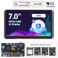
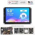
- Available in multiple sizes: 5.0/7.0/9.0/10.1 inches, IPS TFT screens support capacitive touch, wide viewing angles, and smoother interaction.
✅ Integrated intelligent vision, empowering AI applications
- An integrated 2-megapixel MIPI-CSI camera smoothly runs AI vision algorithms like facial recognition and object tracking.
✅ Rich and comprehensive interfaces for flexible expansion
- Dual USB-C (supporting UART debugging and USB 2.0 Device), 11pin GPIO, and Crowtail (I2C/UART) interfaces facilitate connection to various peripherals and sensors.
- A replaceable wireless module slot supports multiple communication protocols, including Wi-Fi 6, Thread, Zigbee, and Wi-Fi Halow, allowing a single board to accommodate diverse IoT scenarios.
Application scenarios
- Industrial automation
- Smart city
- Smart home
- Medical equipment
- Agricultural technology
- Environmental monitoring
- Energy management
- Logistics and warehousing
- Retail and catering
- Education and research
Target Group:
Engineers and technicians, system integrators, facility managers, R&D personnel, agricultural workers, environmental scientists, medical professionals, retailers and restaurant owners, educational institutions, energy companies, etc.
Specification
|
Main Chip-ESP32-P4NRW32 |
|
|
CPU/SoC |
ESP32-P4 RISC-V 32-bit dual-core processor for HP systems, running at up to 400 MHz; RISC-V 32-bit single-core processor for LP systems, running at up to 40 MHz |
|
System Memory |
|
|
Memory |
|
|
Development Environment |
ESP-IDF、Arduino IDE |
|
Screen |
|
|
Size |
9.0 inch |
|
Resolution |
1024*600 |
|
Display Panel |
IPS Panel |
|
Touch Panel |
Capacitive Touch, Single/5-point Touch |
|
Viewing Angle |
178° |
|
Brightness |
400 cd/m²(Typ.) |
|
Color Depth |
16.7M (8-bit) |
|
Wireless Communication - Onboard Antenna |
|
|
WiFi |
Support 2.4GHz(Wi-Fi6), 802.11a/b/g/n |
|
Bluetooth |
Support Bluetooth 5.3 and BLE |
|
Other |
Zigbee、LoRa、nRF2401、Matter、Thread and Wi-Fi Halow (Optional) |
|
Interface/Function |
|
|
Interface |
USB2.0, UART, I2C, GPIO female headers, SD card holder, battery socket, speaker jack, camera header, module female headers, etc. |
|
Function |
Audio amplifier, battery charge management, USB to UART, microphones, dual speakers, etc. |
|
Speaker Connector |
|
|
Model |
BX-PH 2.0-2PWT |
|
Number of Pins |
1x2P |
|
Pin Pitch |
2mm |
|
Dimensions(L*W*H) |
8*8.5*5.6mm |
|
Monting Type |
SMT Right Angle |
|
Button/LED Indicator |
|
|
Reset Button |
Yes, press to reset device |
|
Boot Button |
Yes, press and hold the power button to burn the program |
|
Power Button |
Switch On/Off |
|
PWR |
Device power on/off indication |
|
CHG |
Lithium battery charging status, Low battery state |
|
Other |
|
|
Installation method |
All around mounting holes(M3 3.2mm), embedded, shell assembly |
|
Operating temperature |
-20~70 °C |
|
Storage temperature |
-30~80 °C |
|
Power Input |
5V/2A, USB or UART terminal |
|
Dimensions |
222*130*16mm |
Three Wireless Module Details
- ESP32-H2 Wireless Module
|
Pin |
Pin Direction |
Note |
|
U1RXD |
Input |
Serial port 0 receiving pin |
|
U1TXD |
Output |
Serial port 0 receiving pin |
|
GPIO12 |
Input/Output |
GPIO |
|
GPIO13 |
Input/Output |
GPIO |
|
GPIO14 |
Input/Output |
GPIO |
|
3V3 |
|
Power supply |
|
GND |
|
Ground wire, connected to the power reference ground |
|
GPIO1 |
Input/Output |
GPIO |
|
GPIO0 |
Input/Output |
GPIO |
|
GPIO2 |
Input/Output |
GPIO |
|
GPIO22 |
Input/Output |
GPIO |
|
GPIO10 |
Input/Output |
GPIO |
|
GPIO11 |
Input/Output |
GPIO |
|
BOOT |
Press and then tap the RST key to enter the burning mode |
|
|
RST |
Press it to re-run the program and also to burn the program. |
|
Chip performance
|
Chip Model |
ESP32-H2FH4 |
|
|
FLASH |
4MB Quad SPI |
|
|
SRAM |
320KB |
|
|
ROM |
128KB |
|
|
LP memory |
4KB |
|
|
Ambient temperature |
-40℃~105℃ |
|
|
Voltage |
3.3V |
|
|
Bluetooth Low Energy Radio Specifications |
||
|
Working channel center frequency range |
2402~2480MHz |
|
|
RF transmission power range |
-24.0~20.0dBm |
|
Patch Antenna Performance
|
Gain and efficiency |
Bandwidth 2.4G~2.5GHz |
|
Peak Gain |
4.33dBi |
|
Average Gain across the band |
4.0dBi |
|
Gain Range across the band |
3.59dBi~4.33dBi |
|
Peak Efficiency |
62.5% |
|
Average Efficiency across the band |
57.5% |
|
Efficiency Range across the band |
51.3%~62.5% |
- nRF2401 Wireless Module
|
Pin |
Pin Direction |
Note |
|
CE |
Input |
Module control pin |
|
SCK |
Output |
SPI Data Pin |
|
MISO |
Input |
SPI Data Pin |
|
MOSI |
Output |
SPI Data Pin |
|
3V3 |
|
Power Supply |
|
GND |
|
Ground wire, connected to the power reference ground |
|
CSN |
Input |
Module chip select pin, used to start an SPI communication |
|
IRQ |
Input |
Module interrupt signal output, low level is effective |
Chip performance
- Chip Model: nRF24L01+
- Worldwide 2.4GHz ISM band operation
- 250kbps, 1Mbps and 2Mbps on air data rates
- Ultra low power operation
- 11.3mA TX at 0dBm output power
- 13.5mA RX at 2Mbps air data rate
- 900nA in power down
- On chip voltage regulator
- 1.9 to 3.6V supply range
Patch Antenna Performance
|
Gain and efficiency |
Bandwidth 2.4G~2.5GHz |
|
Peak Gain |
3.74dBi |
|
Average Gain across the band |
3.66dBi |
|
Gain Range across the band |
3.45dBi~3.74dBi |
|
Peak Efficiency |
58.9% |
|
Average Efficiency across the band |
55.9% |
|
Efficiency Range across the band |
53.0%~58.9% |
- SX1262 Wireless Module
|
Pin |
Pin Direction |
Note |
|
DIO1 |
Input/Output |
Configurable general purpose IO ports |
|
SCK |
Input |
SPI Data Pin |
|
MISO |
Input |
SPI Data Pin |
|
MOSI |
Output |
SPI Data Pin |
|
3V3 |
|
Power supply |
|
GND |
|
Ground wire, connected to the power reference ground |
|
NRESET |
Output |
Chip reset trigger input pin, low level is effective |
|
DIO2 |
Input |
RF switch send/receive control pin, low level is receiving, high level is sending |
|
BUSY |
Output |
Used for status indication |
|
NSS |
Input |
Module chip select pin, used for SPI communication |
|
DIO3 |
Input/Output |
Configurable general purpose IO ports |
Antenna Performance
|
Gain(dBi) |
3.5dBi |
|
VSWR |
<=1.9 |
|
Input impedance(Ω) |
50 |
|
Polarization |
Vertical |
|
Lightning Protection |
DC Ground |
|
Mechanical Specification |
|
|
Wire Spec |
RF1.13 |
|
Wire length(cm) |
10cm |
|
Input connector type |
IPEX-1 |
|
Antenna weight(kg) |
0.01 |
|
Operating temperature |
-40℃~85℃ |
Display Pin Definition
|
Pin |
Description |
Connector Type |
|
SPK |
Output audio signal and connect to speakers. The mainboard has a power amplifier chip circuit. |
PH2.0-2P |
|
PWR |
Power LED |
|
|
RST |
Reset button. Press it to reset the system. |
|
|
BOOT |
|
|
|
UART0-OUT |
Build communication between Logic modules, including serial communication module and printing module. |
HY2.0-4P |
|
UART1-OUT |
Build communication between Logic modules, including serial communication module and printing module. |
HY2.0-4P |
|
UART1-IN |
|
HY2.0-4P |
|
I2C-OUT |
Establish communication between microcontroller and peripheral devices. |
HY2.0-4P |
|
BAT |
Connect lithium battery. (With battery charging circuit) |
PH2.0-2P |
For more pin functions, see Wiki.
Package List
- 1x CrowPanel Advance ESP32-P4 Display-9.0 inch
- 1x USB-A to Type-C Cable
- 1x Crowtail/Grove 4pin DuPont cable
- 1x Wireless Module-ESP32-H2 Optional
- 1x Wireless Module-nRF2401 Optional
- 1x Wireless Module-WiFi Halow Optional
- 1x Wireless Module-LoRa( with 868Mhz/915MHz Copper Tube Spring antenna) Optional
Wiki & External links
- Wiki of ESP32-P4 9inch HMI Display
- User Manual of ESP32-P4 9inch HMI Display
- CE Report of ESP32-P4 9inch HMI Display
- RoHS Report of ESP32-P4 9inch HMI Display
- FCC Report of ESP32-P4 9inch HMI Display
- ESP32-P4 Datasheet of ESP32-P4 9inch HMI Display
- IDF User Lessons of ESP32-P4 9inch HMI Display
- Arduino User Lessons of ESP32-P4 9inch HMI Display
- ESP Home Tutorial of ESP32-P4 9inch HMI Display
- Guide to Upgrading the C6 Firmware Using the ESP32-P4 Chip
What do they say?
| Cambio PROGETTO ???? Riprendo il CRUSCOTTO DIGITALE ma FINISCE in un modo che davvero non CREDEVO! |
|
| Youtuber: STEPSOVER EXTRA | |
| Sain 9” AI-näytön testiin – tein siitä Home Assistant -kojetaulun | |
| Youtuber: Protoboksi |
Write Your Own Review
-
 A reusable template for makers: touch UI, instant reaction, and MCU-based neural speech. CrowPanel UI + TinyTTS voice: instant offline speech on the MCU, ready to extend and remake.
Build a Talking Quiz About Animals
14868180 -
 A weather station that talks, powered by real on-device neural speech. Build it once — then make anything you want speak.
Hear Your Weather — Build a Talking Weather Station
1398181 -
 Beyond Beeps and MP3 Clips: Real Voice on MCUs.
The First Neural Speech Module for Makers: tinyTTS kit
175805310 -
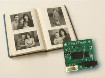 Your pictures don’t just sit there anymore — they speak. Add short captions to your family album, and turn them into natural voice
TinyTTS — The Neural Module That Makes Photos Talk
1337180 -
 Connect your device via USB, launch the app, paste Wi-Fi and keys, click "Send" — done in 10 seconds.
Send Wifi, Keys & Initial Data over USB from PC to CrowPanel
11745200 -
 An interactive English learning game enhanced with CrowPanel, adding voice recognition, scoring, and real-time visual feedback for kids.
CrowPanel Game Interface for AI Learning
1561180 -
 Displays real-time indoor data (temperature, humidity, pressure, IAQ, CO₂, VOC) and live weather forecasts. Easy setup with prebuilt firmware. Fully open-source and customizable.
Weather & Air Quality Station (EnSens Add-on & CrowPanel)
15263191 -
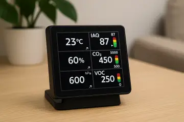 Turn your CrowPanel Advance into a smart indoor air monitor with the EnSens Add-on. Get real-time data on temperature, humidity, pressure, IAQ, CO₂, and VOCs—visualized with trend arrows and color alerts. Easy plug-in setup, open-source firmware, and instant installation.
MiniMeteo: Compact Indoor Air Quality Station for CrowPanel
9503180 -
 Voice-controlled robot interface using CrowPanel Advance and OpenAI. Spoken commands are interpreted via API and sent over Bluetooth to a robot. Works with CrowBot and can be adapted for other devices.
Natural Language Robot Control via CrowPanel + OpenAI
3727407 -
 A ready-to-use weather station. Quick setup: flash the prebuilt firmware and start testing in under a minute, no coding required. Open-source and customizable for your own weather-based projects. Firmware and source code available on GitHub.
Simple Weather Station on CrowPanel Advance
5252342 -
 OpenAI Terminal is an AI-powered voice assistant designed for the Elecrow CrowPanel Advance. It enables real-time communication with OpenAI models via WebRTC, providing hands-free interactions. Users connect via Wi-Fi, authenticate with an OpenAI API key, and access features like live transcriptions and model responses.
Open AI Terminal
4711335 -
 Turn the Elecrow CrowPanel on ESP32-P4 into an interactive AI storybook with animated scenes, local voice playback, and touch interaction
Magic Talking Storybook on ESP32-P4
7021160

Bestselling Products You May Like


New Products You May Want

Warranty
Service
VIP Distributor
Discount
Professional
Tech Support
Fast
Delivery
×
 Add to cart successfully!


Customers Who View This Item Also Bought