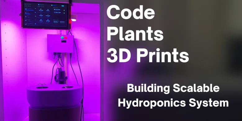


Story
It all started with my wife's impressive talent for turning our apartment into a botanical graveyard. Despite her superhuman ability to remember every anniversary and organize our entire social calendar, she somehow managed to kill plants with the efficiency of a natural disaster. Between her busy schedule and our tiny apartment space, our poor plants were either drowning in guilt-watering sessions or dying of neglect. The situation reached a breaking point when she discovered a succulent that had somehow managed to both drown AND dehydrate simultaneously. Meanwhile, I was already on thin ice after my Anycubic Vyper 3D printer had claimed half the living room, producing nothing but an army of benchy boats and one very sad Baby Yoda that looked like a melted green candle. With the printer now living in shame under a sheet and my wife's firm "NO MORE LARGE DEVICES" decree, I found myself in desperate need of a new hobby.
What if I could solve multiple problems with one elegant solution? I needed to build a cheap, compact hydroponic system that could keep my wife's plants alive without taking over our living space, grow plants faster than traditional methods, and be scalable enough to expand into a full vegetable garden when we eventually move to a bigger place.
Initial Requirements:
- The 3D Printed parts must fit within my 3D printer's build volume (245 x 245 x 260 mm)
- Incorporate wood into structural elements - for that "I'm a sophisticated maker, not just a guy with a plastic addiction" aesthetic.
- Design a neat control board capable of managing both 5V DC (USB) devices and 12V DC devices
- Include WiFi and ESP-NOW capabilities - because if my plants can't communicate wirelessly, what's even the point?
- Add RS485 for wired communication - because sometimes you need a backup plan when wireless decides to have a bad day
- Control exactly three devices: grow lights, aerator pump, and main irrigation pump - the holy trinity of hydroponic automation
- Provide 3x USB outputs and 3x 12V outputs - because flexibility is key when you're not entirely sure what voltage your future plant gadgets will demand
- Keep total power consumption between 10W and 35W with all devices running - my electric bill was already questionable thanks to the 3D printer
- Enable 24/7 operation with 24-48 hour power outage survival - because plants don't care about power grid failures, and neither should my system
- Use only easily sourceable and cheap components - because explaining expensive failures would be harder than keeping the plants alive
Section 1 : Building the Hydroponic Setup.
Please downaload and print all the STL files in the repository
-
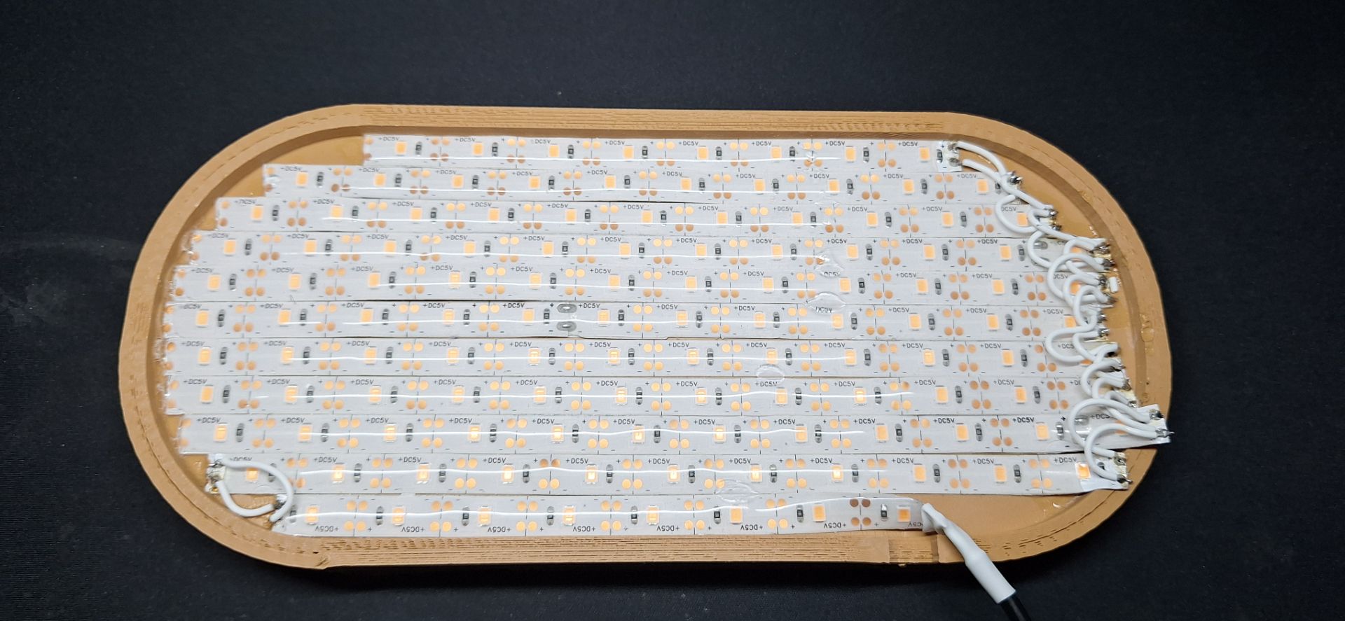
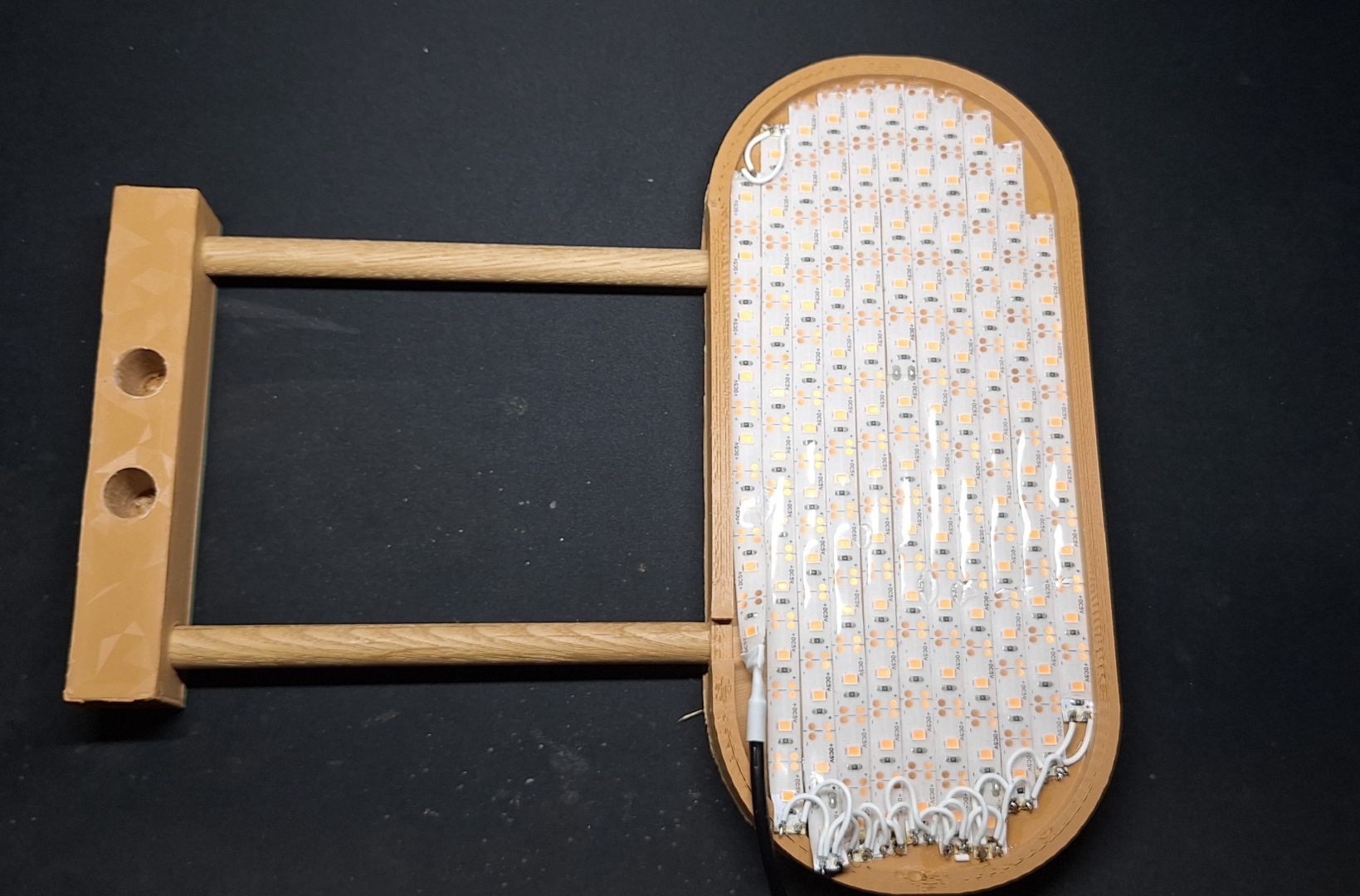
Cut the LED grow light strip into small segments and stick them onto the light_strip_holder 3D printed part and solder them as shown in the picture.
-
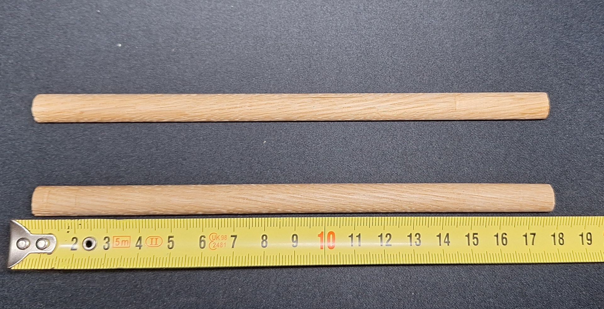
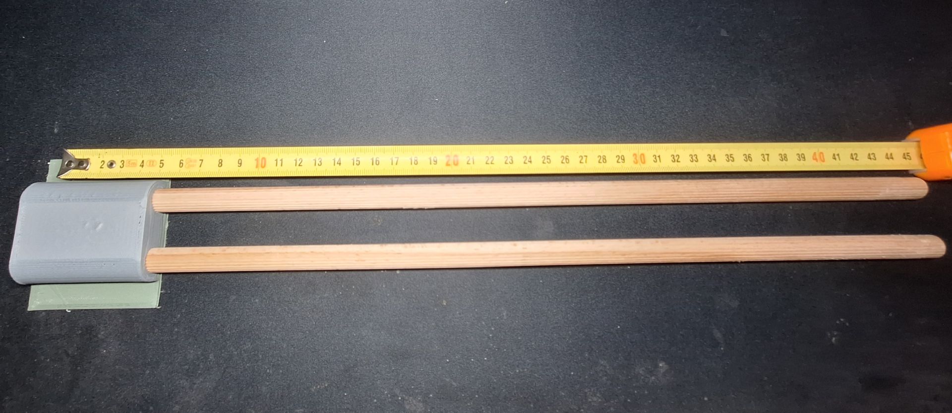
Cut 2 segments of 18cm from the 1 meter 8mm wooden rod.
-
Insert the rods into the holes of the light_strip_holder 3D printed part.

-
Insert the other end of the rods into the matching holes of the light_holder_elbow 3D printed part as shown in the image below.
-
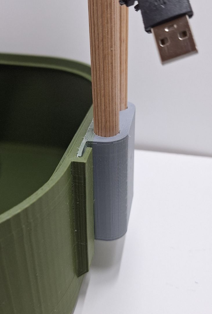
Cut 2 segments of 45cm from the 1 meter 12mm wooden rod and insert them into the holes in the light_holder_support 3D printed part as shown in the image below.
-
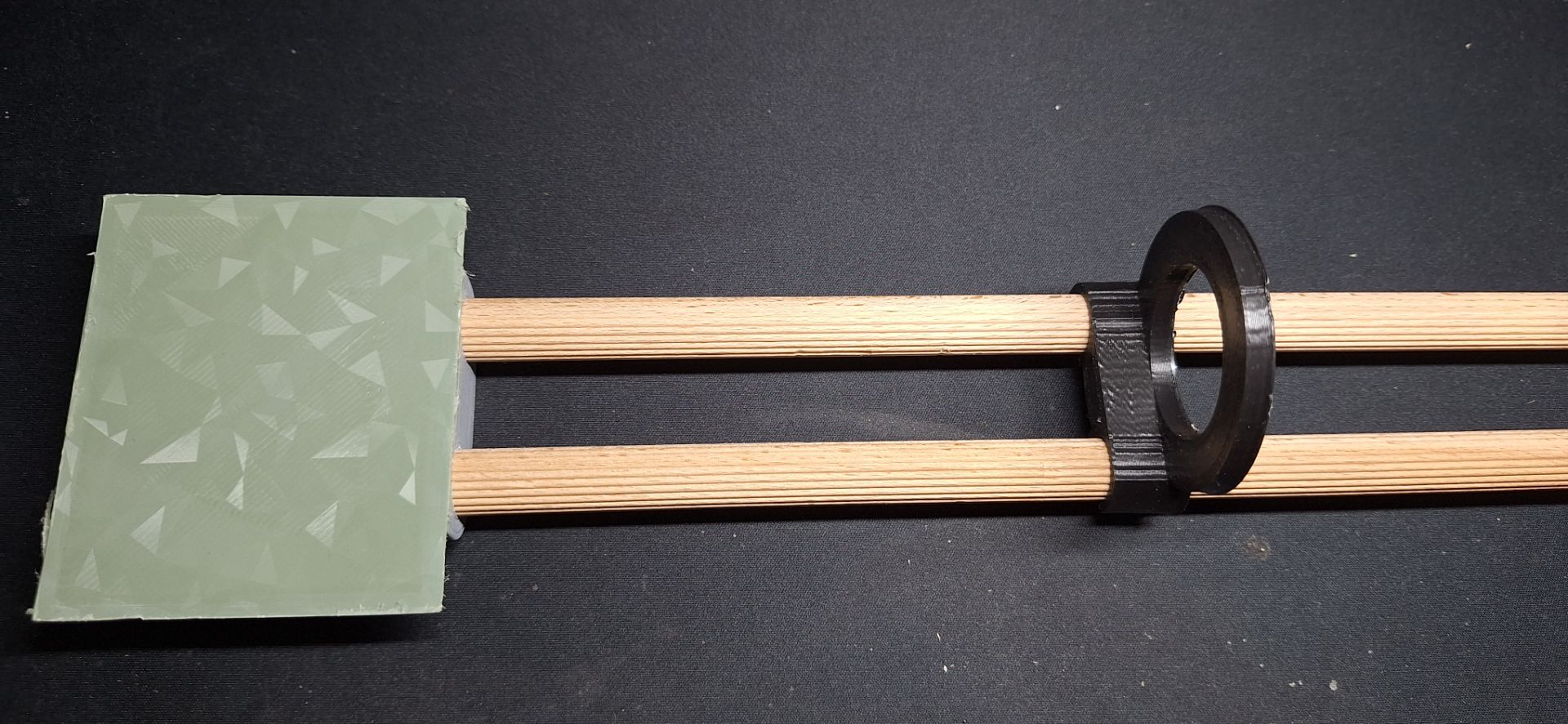
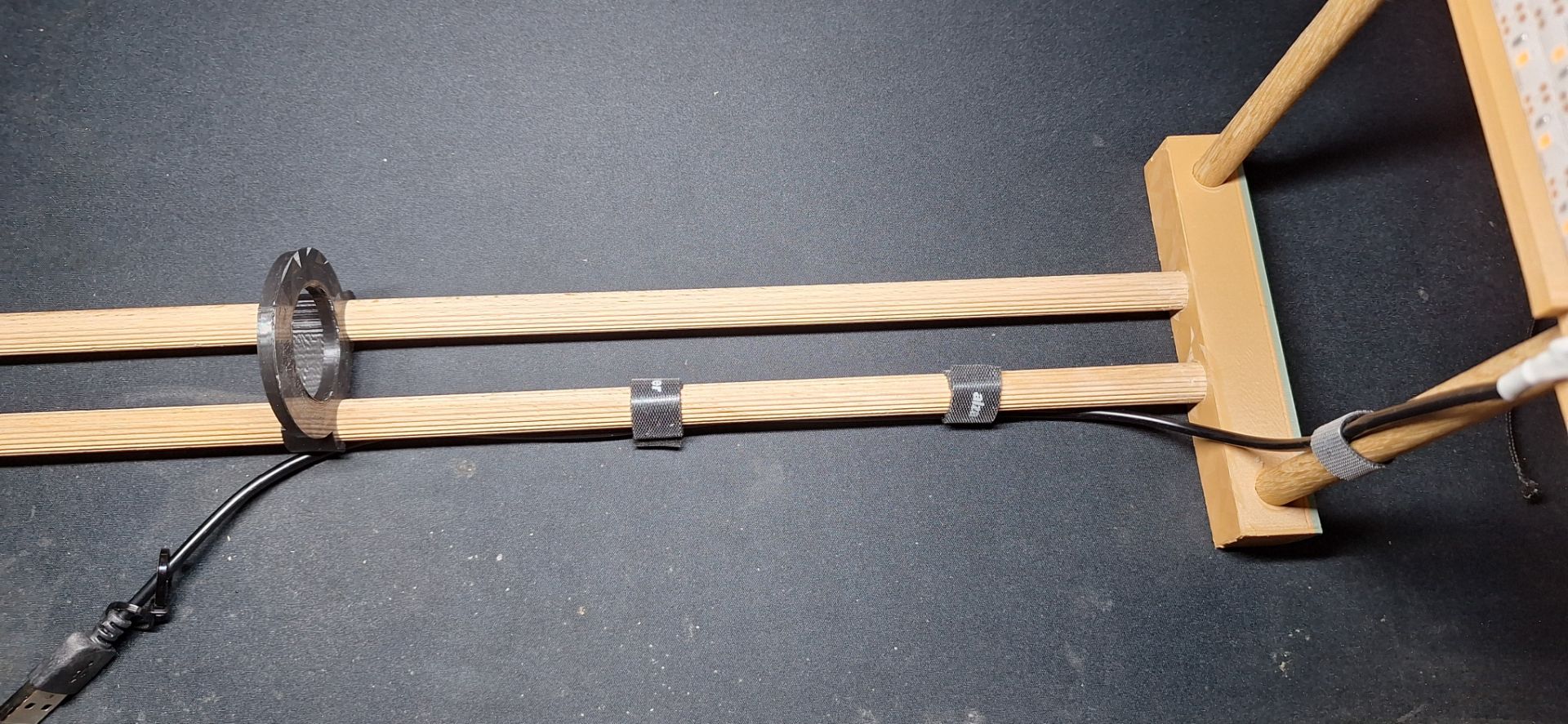
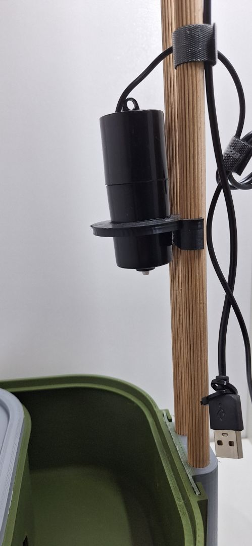
Clip on the aerator_clamp 3D printed part to the 12mm wooden rods as shown in the image below.
-
Your assembled part should look like the image below.
-
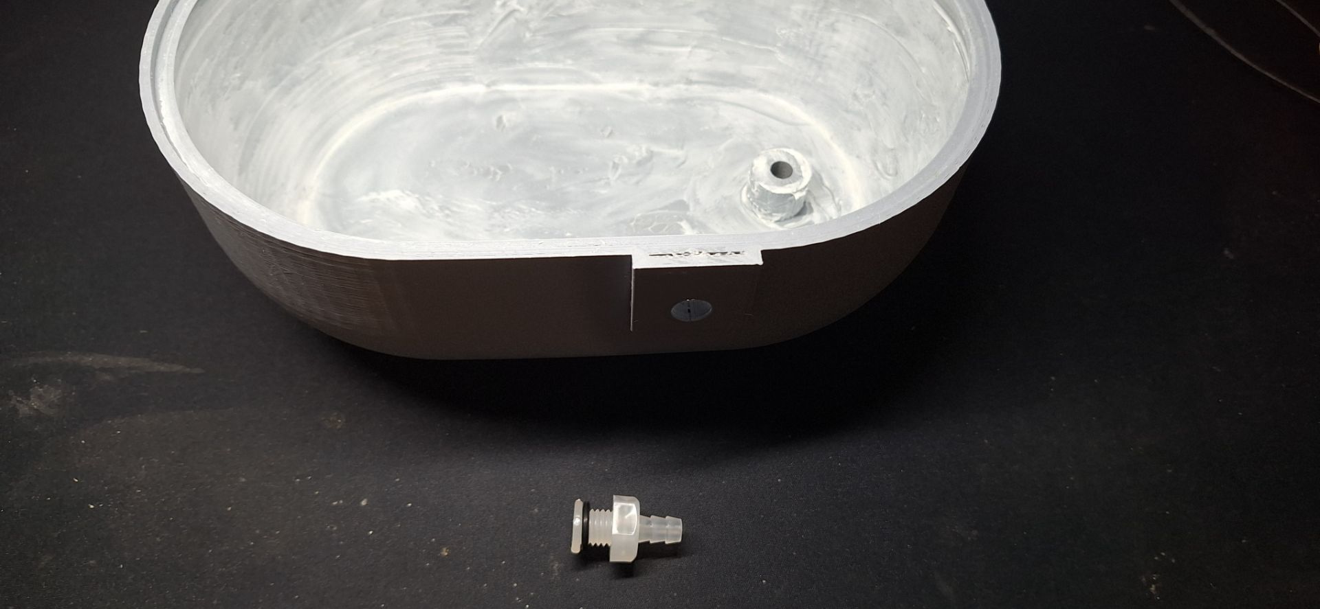
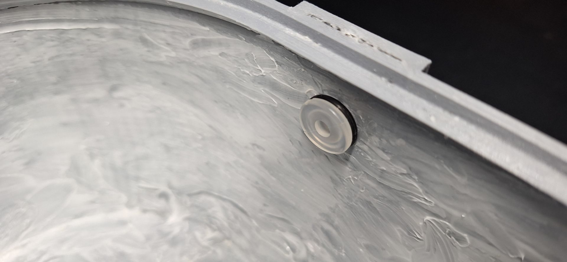
Insert the M10-6mm Pagoda connector through the hole in the grow_pot 3D printed part as shown in the image below.
-
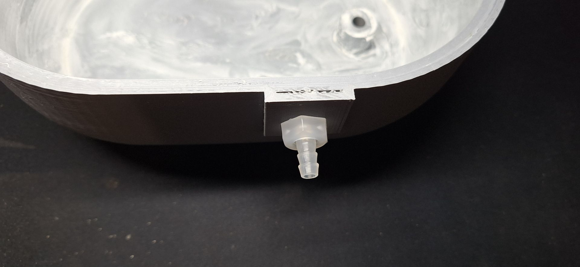
Screw on the pagoda connector as shown in the image below.
-
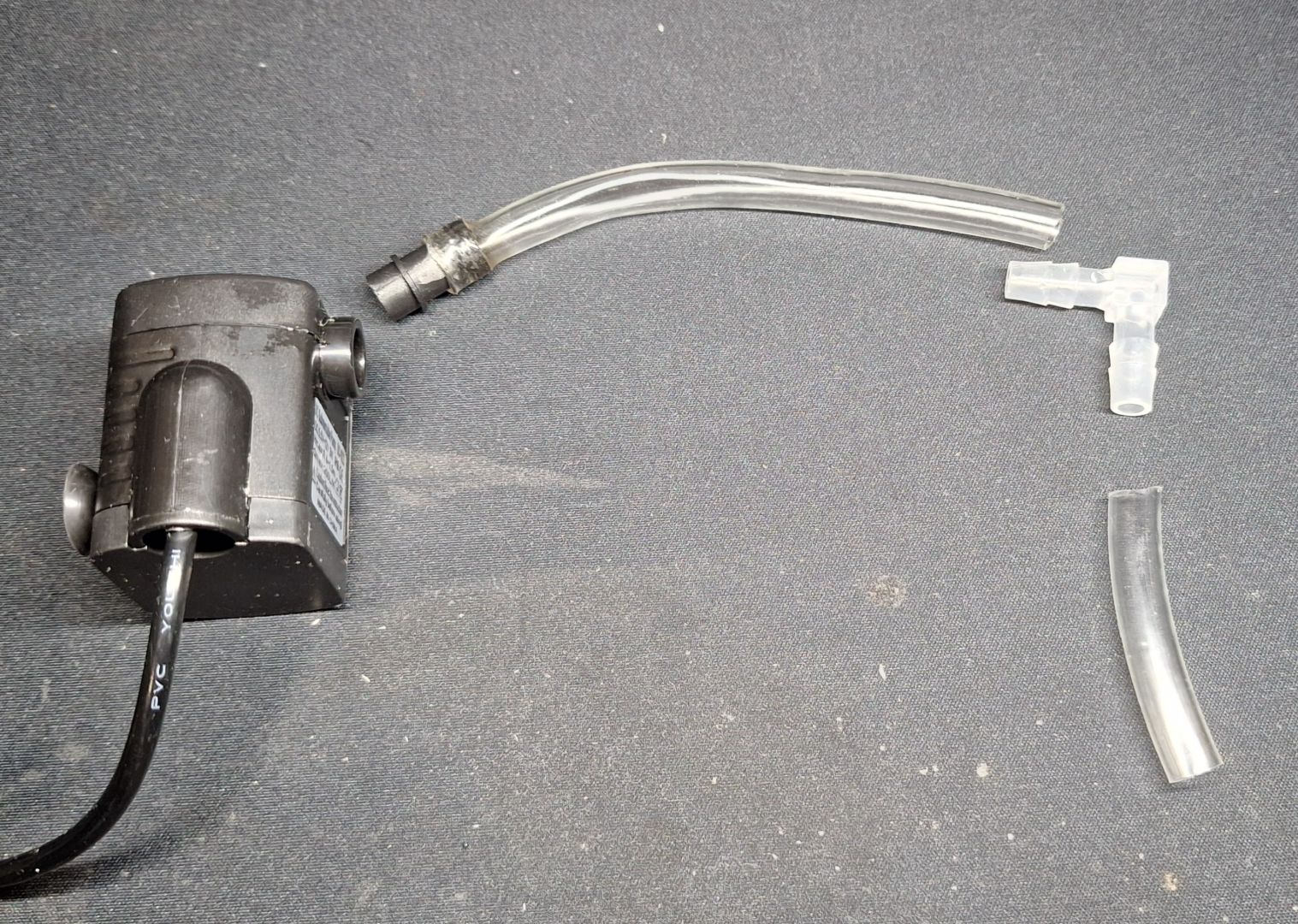
Cut the "6mm ID / 8mm OD" tube into segments of 10cm and 4cm as shown in the image below.
-
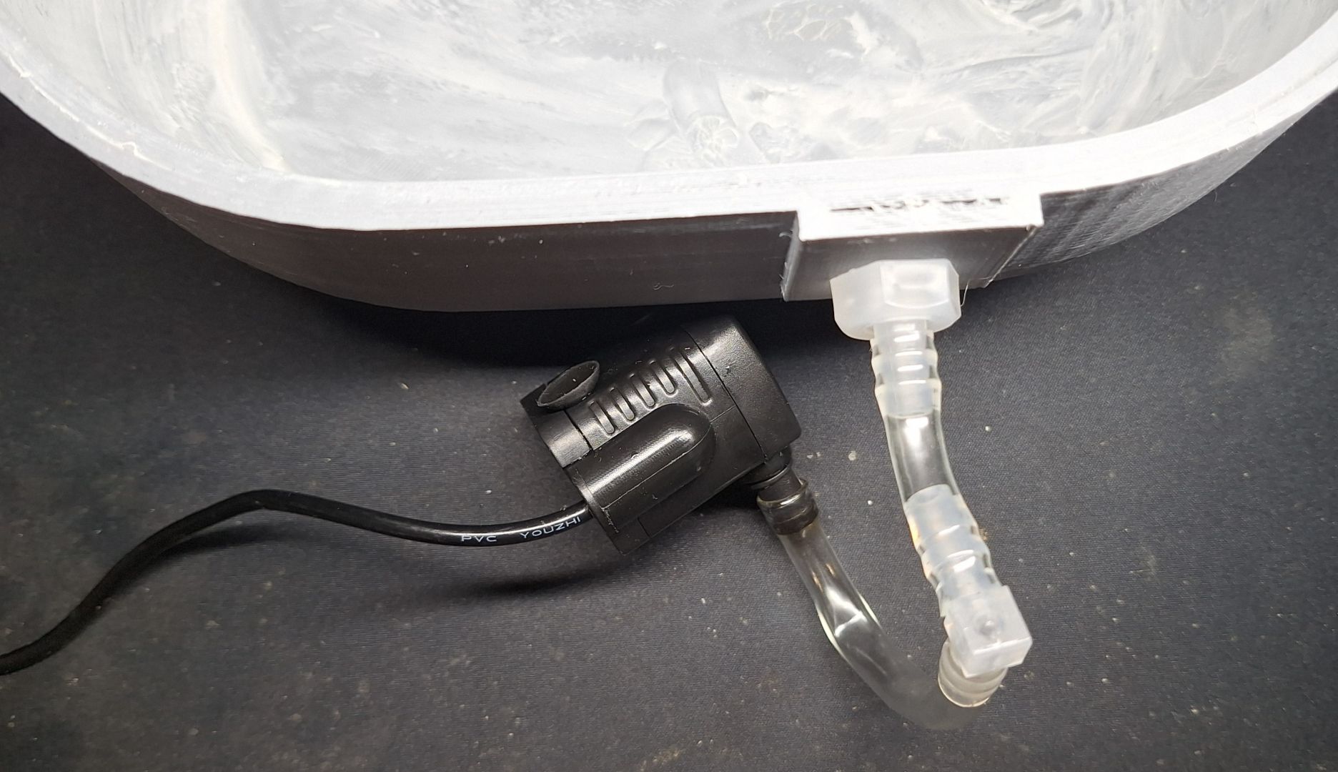
Connect the tubes to the pump and pagoda elbow connector as shown in the image below.
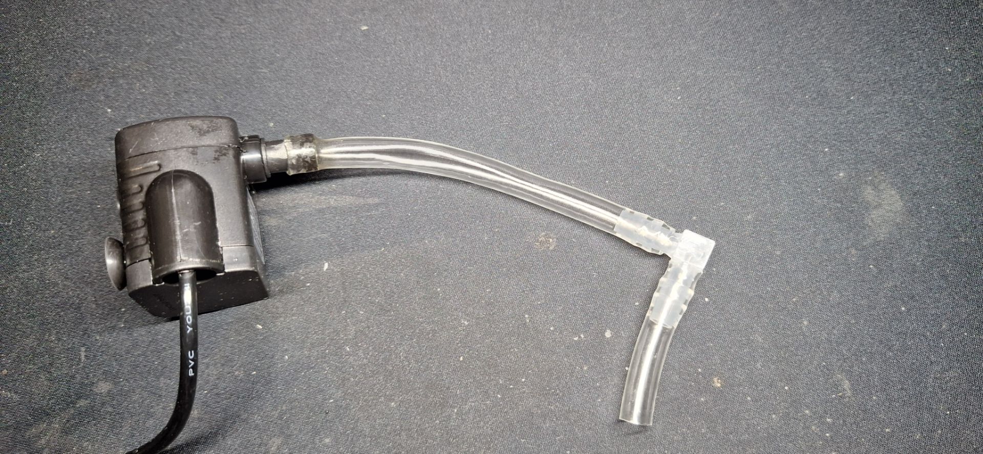
-
Connect the other end of the pipe to the pagoda connector sticking out of the grow_pot 3D printed part.
-
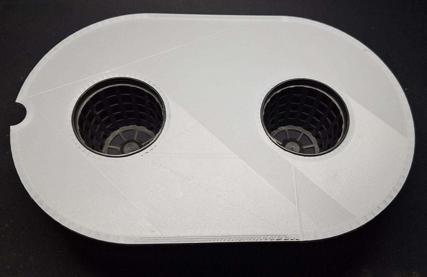
Insert the net pots into the holes of the net_pot_holder 3D printed part as shown in the picture below.

-
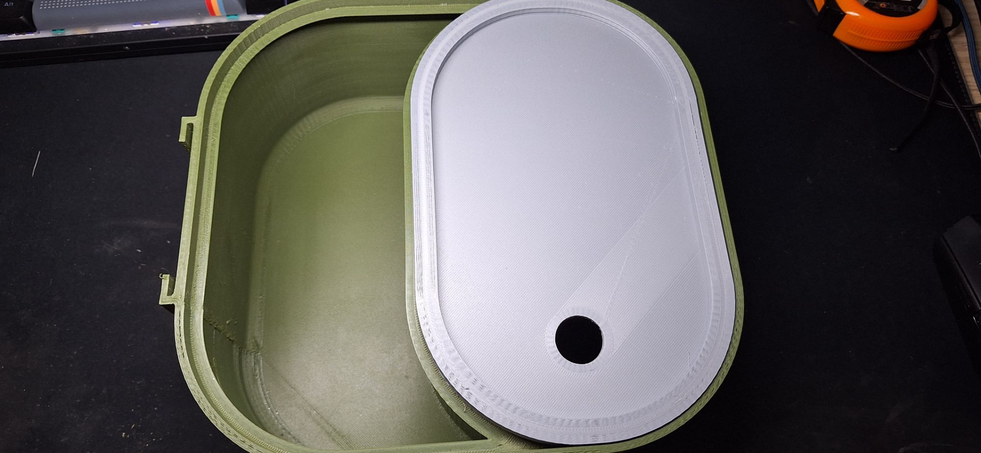
Place the front_middle_plate 3D printed part on top of the reservoir 3D printed part as shown in the image below.
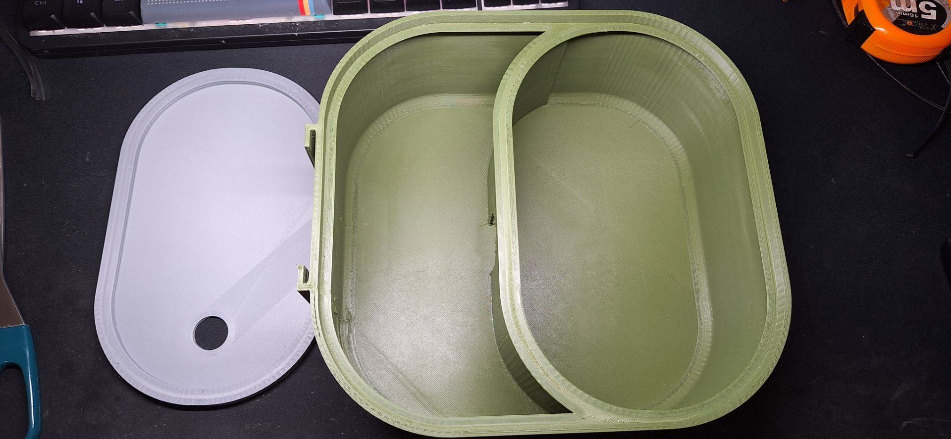
-
Slide the top assembly which we made in steps 1 to 7 into the slot behind the reservoir 3D printed part as shown in the image below.
-
Insert the aerator into the aerator clamp as shown in the picture below.
-
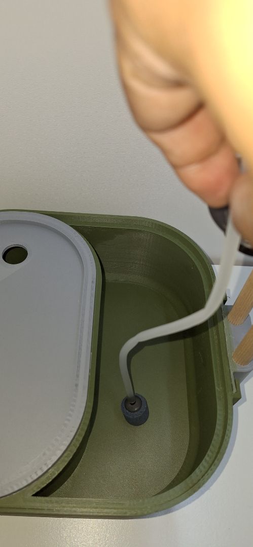
Measure and cut the air tube so that the stone diffuser touches the bottom of the reservoir as shown in the picture below. Then attach the tube to the aerator.
-
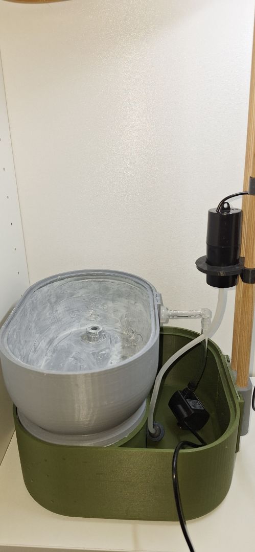
Place the grow_pot assembly on top of the front_middle_plate part on top of the reservoir as shown in the picture below.
-
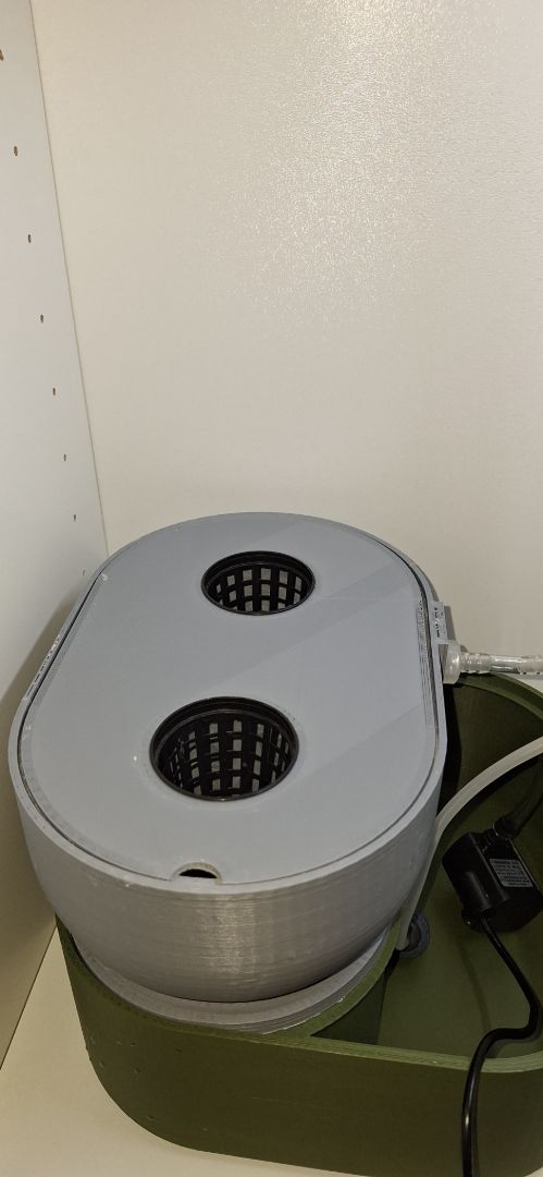
Place the net_pot_holder assembly which we made in step 13 on top of the grow_pot as shown in the picture below.
-
Install the reservoir_splash_cover part on the reservoir as shown in the image below.

-
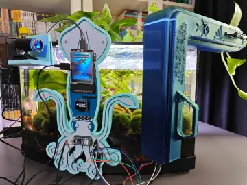
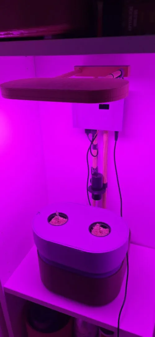
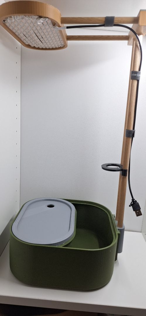
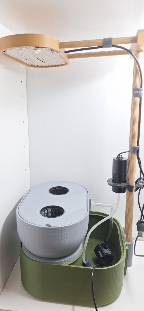
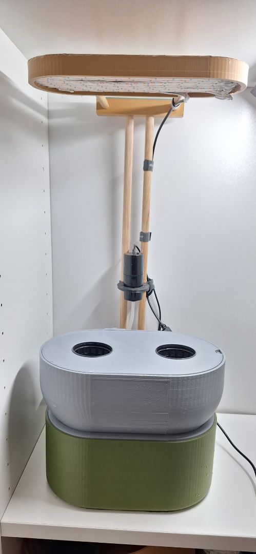
Congratulations! You have successfully built the setup and it should look like the image below.
Section 2 : Irrigation Node.
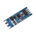
You can wire up the parts like the diagram below for the DIY version.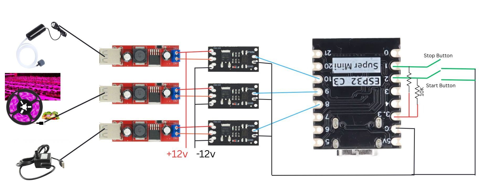
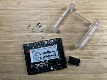
or you can download the gerbers from the github repository and fabricate and assemble PCB for the PCB version.
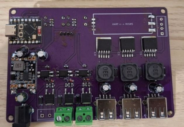
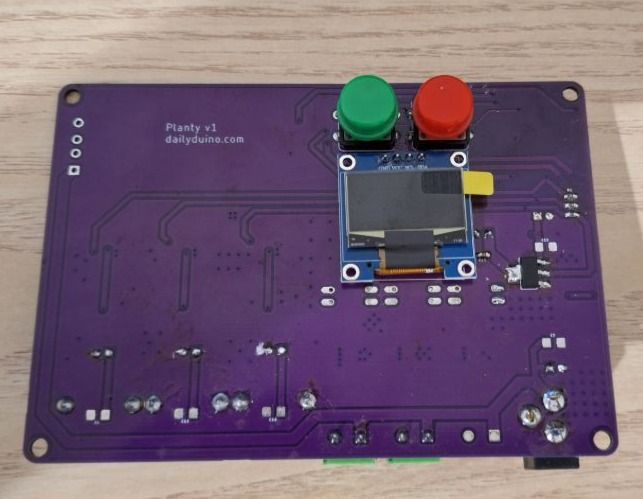
( forgot to clean the board before taking pictures)
Then you can flash the firmware using Arduino for both DIY version and PCB version from HydroControl-Irrigation-Node-Firmware
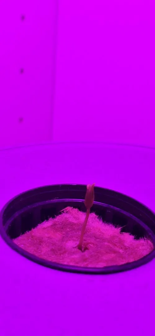
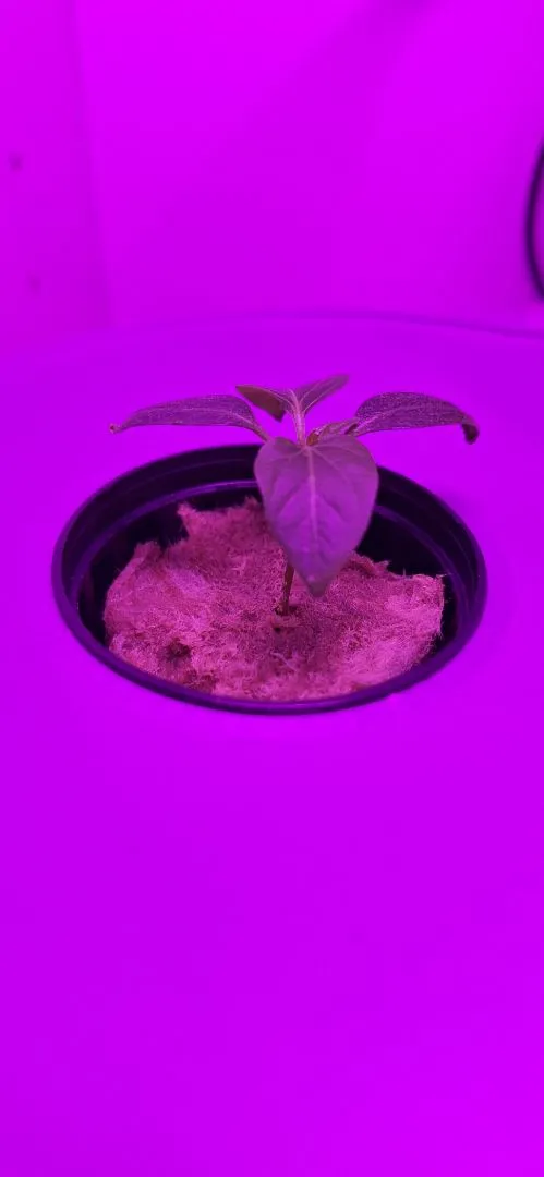
After flashing the firmware all you have to do is press the start button and see the device come to life.
Then you can fill the reservoir and seed the netpot with grow medium.
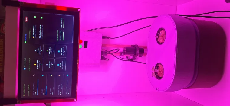
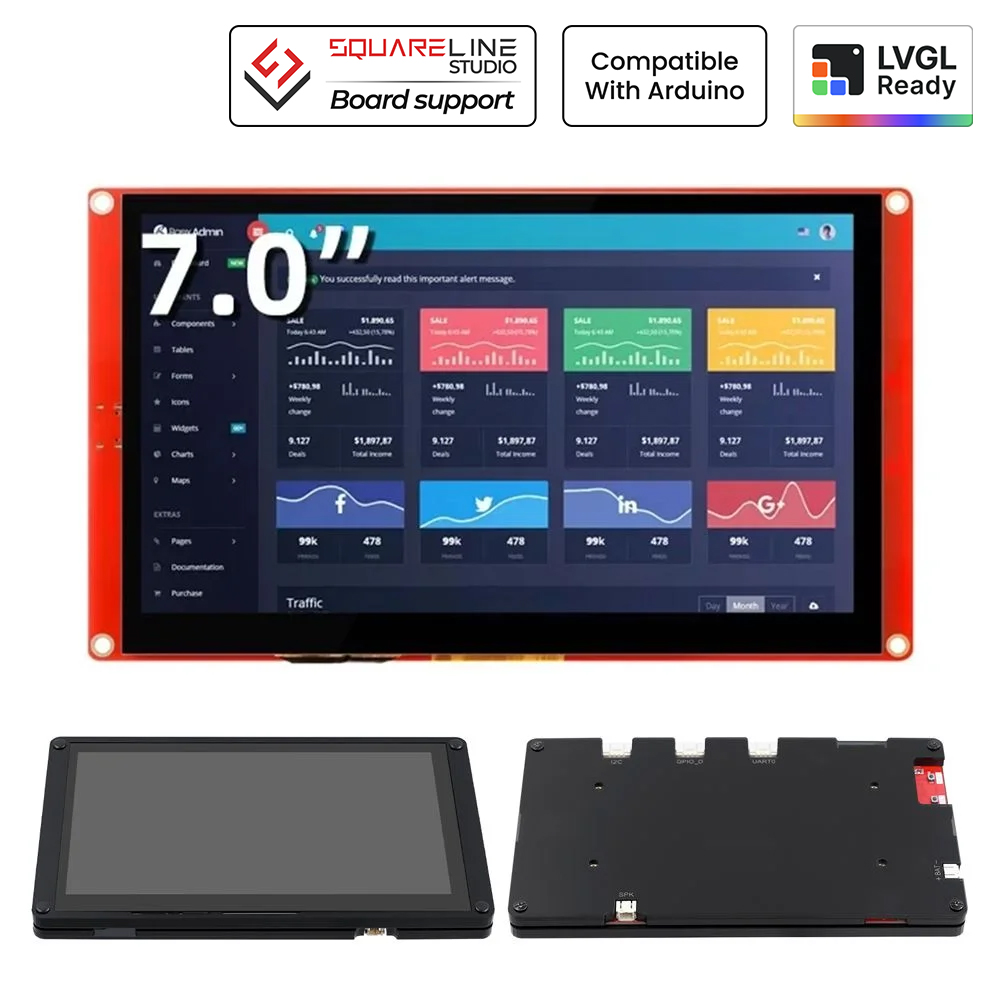
Section 3 : HMI with CrowPanel 7"
It is nice to have an Interface to know how my plants are doing and also from where i can control all my connected nodes. So, CrowPanel was my first choice because it has ESP32-S3 and LVGL Support.
Download Code from HydroControl-Crowpanel-Hydroponics-Firmware
Open it in PlatformIO + VSCode
Edit the Mac address of your Climate node and Irrigation node
Connect your crowpanel to usb
Then upload the code.
Then you should see a display like below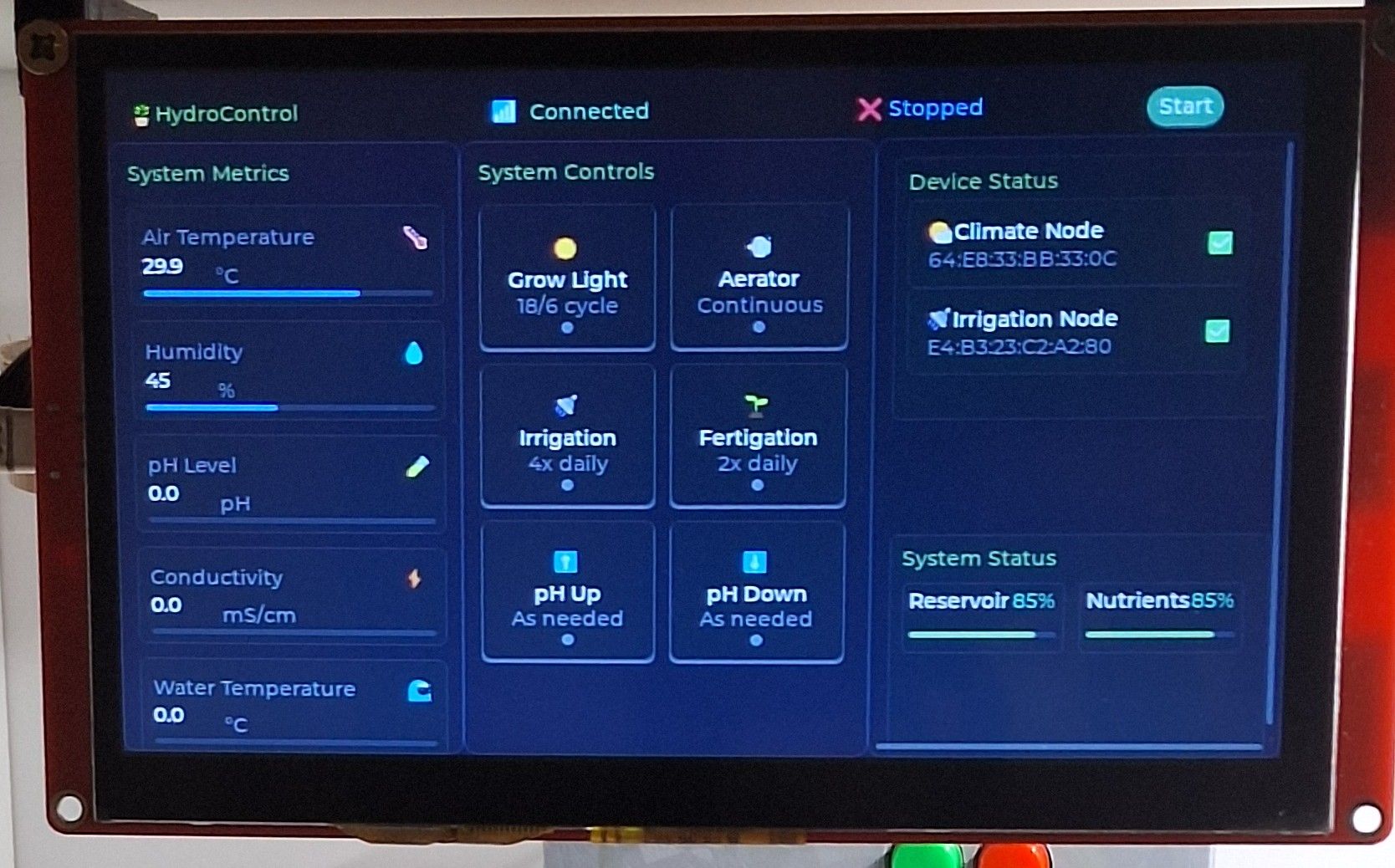
Section 4 : Climate Node
Wire the SHT31 Sensor and ESP32-C3 super mini like shown in the image below.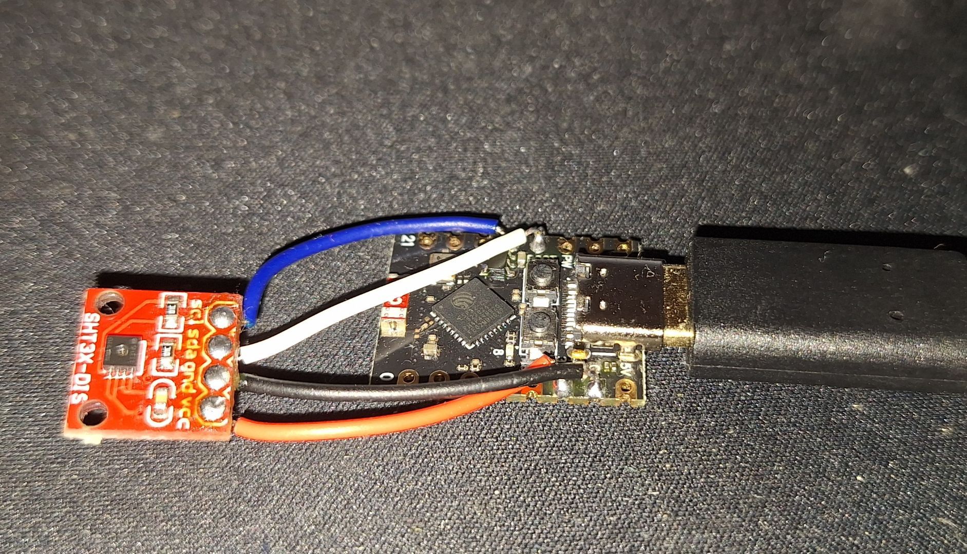
Download the arduino code from https://github.com/Cyrilanthony777/HydroContol-Climate-Node-Firmware
and flash the firmware to ESP32 Super mini.
Your sensor data should show up in the CrowPanel 7" Display.
Awesome!! You have successfully build a self sustaining hydroponics mini farm