Story
Programming and Development Board for PIC uC
Programmer and development board for PIC microcontrollers
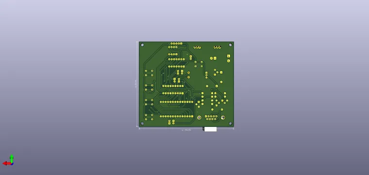
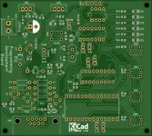
This application is, in addition to a means of practicing practical electronics, a hobby, a way to obtain your own multifunctional board for microcontrollers and a way to use original software (PROGPIC2). This circuit is a multifunctional programmer for the PIC microcontroller family from Microchip. Among the types of uC PIC can be programmed (from those with 8 pins to those with 28 pins). A group of 6 LEDs and 4 push buttons with normally open contact, facilitates the uC testing programmed directly in the socket in the programmer. PIC microcontrollers of another type (over 28 pins, for example PiC16F877) or those packaged in a different type of capsule than the DIP, can be programmed directly in the circuit, through the ICSP connector on the board.
The programming software is called PICPROG2.
It is noted the use of only discrete components, practically without any specialized integrated circuit; this aspect makes this application even more interesting. The conversion of RS232 format signals into TTL (0-5V) signals is performed with general purpose transistors, configured as inverters. This is the case of transistors T1, T2, T3 or T4. The serial port lines, RTS and DTR (pins 7 and 4), from SK2, are used as
clock and data (for uC programming pins, respectively PGC and PGD), and Tx (3), CTS (8) and RI (9) to check and / or control the programming operation.
The entire circuit is powered by at least 15V through connector SK1. The programming value, high value (VPP) of approximately 13.5V (and which is applied on the MCLR / Vpp pin of uC) is obtained from the VR1 controller (L7812). It is mounted in series with the pin reference, to ground, diodes D2 and D3, Thus, at its output, the voltage increases from 12V to 13.5V. From the voltage of 13.5V, there is also the supply voltage of uC, 5V, for the VDD pin, through the VR2 L7805 stabilizer. By switching the jumpers of the SW5 it is possible to choose the working mode: programming, stand-by or testing a program written in uC. Without a jumper, the uC can be inserted into the socket without risk, the programming voltage and the supply voltage do not apply to the uC pins. On the PGM position at SW5A1 it allows the application of the 5V supply voltage (which is signaled by the LD9 LED). The section from SW5B1 at the same time switches the programming voltage of 13.5V to the MCLR pin of the uC. Thus, uC can be programmed with the data arriving from the PC on the DTR line, data that are synchronized with the clock signal on the RTS line. The LD8 LED signals, by activating it, that uC is being programmed. With SW5A1 switched to RUN, uC is normally powered by 5V at the VDD pin and the application registered after programming can be run and tested (viewing the status of the ports defined as LED outputs and / or applying commands from push buttons, on the port line defined as inputs).
For example, when testing an application, the lines defined as outputs (for D1 .... D6) on the board are:
- GP2 and GP4 for 8-pin CPU;
- RC0 ... RC4 for 14-pin CPU;
- RB0 ... RB5 for 18-pin uC;
- RA0 ... RA5 for 28-pin CPU.
As inputs, we use:
- SW1 for GP5 at 8-pin uC;
- SW1 and SW2 for RC5 and RB2 for 14-pin uC;
- pins RA0 ... RA3 at uC with 18 pins for the 4 push buttons;
- for the same 4 switches SW1 ... SW3, pins RB0 ... RB4 from uC with 28 pins.
Applications can be tested with internal or external oscillator (4MHz quartz). The operation is facilitated by jumpers JP1 to P6. The 'Reset' button is also identified on the board. For 8-pin CPU it is not possible to use the external oscillator with quartz crystal. As mentioned above, the SK3 connector facilitates microcontroller programming
mounted in the circuit, without removing or detaching it from the board on which it is mounted. The universally valid programming pins are: VPP, DATA, VDD, CLK and GND.
Note: I am not the original author of this circuit.


