Story
Pulse generator
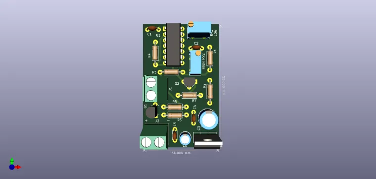
Using this electronic circuit, a very simple pulse generator can be made, using a 4066 circuit.
This pulse generator allows the regulation of the "high" and "low" states of the output signal. (J1).
The durations of the "L" and "H" states of the output signal are adjusted with RV1, respectively RV2. With the values given in the diagram, the duration "L" can be adjusted between 136 us and 3.75 ms, and the duration "H" between 15 us and 330 us. Other durations for the two states can be obtained by changing the values of C2 and C1.
The circuit consumes a current of about 8 mA at a supply voltage of 10 V.
Assuming that switch U1A is open, the control input of U1B is logic high, and this switch is therefore closed. This results in low levels at the control inputs of U1C , and U1D. Capacitor C1 is charged via preset RV1 and C2 via preset RV2. When the voltage across C1 reaches a certain level, U1A is closed so that the control input of U1B is pulled low. The outputs of the circuit, 1 and 2 are then logic high. 1 has a swing o 5V and 2 a swing virtually equal to the supply voltage (max. 15 V). Meanwhile, switch U1C is closed, so that C1 is discharged. Switch U1A is opened, and C2 is charged via RV2. When the voltage across C2 has reached a certain level, is closed, and the outputs of the circuit change to logic low. The ‘low’ and ‘high’ times of the output waveform are adjusted with Rv1 and RV2 respectively. With the component values specified, the ‘low’ time can be set between 136 μs and 3.75 ms and the ‘high’ time between 15 μs and 330 μs
.
Have fun with it !
Note: I am not the original author of this circuit.


