Currency
Toggle Nav

The Ultimate Guide for Industrial PCBA
What is Industrial PCBA?
Industrial PCBA refers to the industrial assembly of a printed circuit board, where all of the electronic components must be assembled for the board to function as designed. Industrial PCBA can also refer to the complex process of assembling the board with critical electronic components.
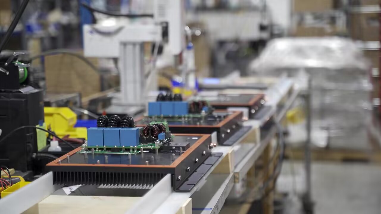
Typically, industrial PCBAs are used for a variety of industrial applications, including robotics, heavy machinery, automotive parts, and medical.
Learn more here:
- Illumination & Lighting Systems
- Consumer & Industrial Electronics
- Aerospace (including satellite systems)
- Telecommunications (including radios, televisions, cell phones and telecom towers)
- Maritime Industry
- Medical & Healthcare (including pacemakers, medical imaging systems)
- Automotive
- Computer Industry
- Printers
- Calculators
- Engine management systems
- Data storage devices
Different Types of Industrial PCBA
There are so many types of industrial PCBs, not only limited to single-layer PCBs, double-layer PCBs (also known as double-layer or double-sided board), multi-layer PCBs, rigid PCBs, flexible PCBs, rigid-flex PCBs, high-frequency PCBs, but also aluminum-backed PCBs, etc.
Single layer PCBs
Sometimes called one-sided PCBs, single-layer PCBs have components on one side of the PCB and a circuit pattern on the opposite side. They have only one layer of conductive material, typically copper. Single-sided printed circuit boards consist of a substrate, conductive metal, solder mask, and screen. Single-sided boards are found in many simpler electronic components.
Double layer PCBs
A double-sided printed circuit board, also known as a double-layer or double-sided board, has more layers than a single-layer board, but fewer than a multilayer board. Double-sided PCBs, like single-sided PCBs, have a substrate layer. The difference is that they have a layer of conductive metal on both sides of the substrate.
Multi-Layer PCBs
Multilayer boards consist of three or more double-sided circuit boards stacked on top of each other. They can theoretically contain any number of boards, but the largest ever made, according to research, was 129 layers thick. More complex devices that require a large number of interconnections typically use multilayer boards. Paths, called vias, allow the different layers to communicate with each other. These vias fall into three groups: Through-Hole, Blind via, and Buried via.
Rigid PCBs
Rigid printed circuit boards generally use FR4 (fiberglass-clad copperplate) printed circuit board as the base material, with solid and non-bendable printed circuit boards for the property of non-bendability, printed circuit boards of this type are referred to as "rigid printed circuit boards.
Flex PCBs
Flex PCBs have a flexible base. Because of their ability to withstand vibration, fold or bend into different shapes, and dissipate heat, flexible circuit boards are becoming increasingly popular in today's electronics.
Rigid Flex PCBs
Rigid flex circuit boards typically consist of multiple layers of flexible circuit substrates that are externally and/or internally attached to one or more rigid circuit boards, then completed in a constant state of flex and typically formed into the flexed curve during manufacturing or installation.
High-Frequency PCBs
HF PCBs (High Frequency Printed Circuit Boards) are available in either rigid or flexible versions and can handle signal rates up to 100 GHz. It is important to note that HF PCBs have lower dielectric constants (Dk), lower dissipation factors (Df), and lower thermal expansion values compared to regular PCBs. HF PCBs are used in a wide range of HDI technology applications. They are used in various industries such as high-speed communications, military, aerospace, automotive, telecommunications, RF microwave technology, etc.

Aluminum PCBs
Aluminum circuit boards dissipate heat better than other circuit boards. Electronic devices typically emit a lot of heat, so heat dissipation is important to keep them stable and functional. Aluminum PCBs often come with an aluminum core followed by FR4. There is a thermal clad that acts as a layer and dissipates the heat accordingly. The main goal is to provide a cooling mechanism for the components.
Tips for Industrial PCB design
When it comes to industrial PCB design, it's important to consider aspects such as defining project requirements, having the right schematics, etc.
Below is a summary of useful tips and terms to look out for:
1. Figure out what your project needs
Find answers to these questions before you begin.
What is the type of your PCBA product?
What is the PCBA's operating environment?
What power options, communication mechanisms, or specifications/regulations does it meet?
Having these answers will help make the design clearer and more practical.
2. Schematics:
In the PCB assembly process, the schematic diagram is the blueprint for PCB manufacturers and assemblers, it shows the symbols of electronic components and their interconnections. When completed correctly, schematics pave the way for the actual product of the PCB project you are designing, ensuring that the PCBA performs as expected, without errors. Eagle, KiCAD, Altium Designer, and OrCAD can be used in this process.
3. Get the BOM:
The Bill of Materials (BOM), created at the same time as the schematic, identifies and locates each component in the circuit; an updated BOM can save a lot of trouble during the PCB design phase.
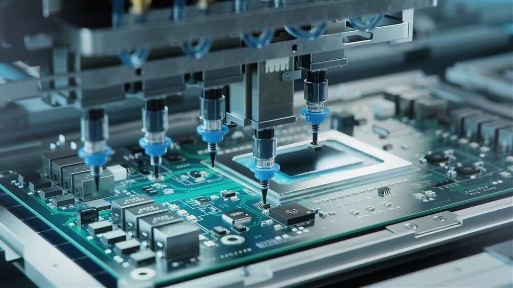
4. Component assembly:
The most critical step in circuit design is placing each component in the correct location on the board. Following the correct component assembly steps is important and sometimes requires professional engineers to complete the entire process. Elecrow offers expert PCBA services that can help you complete the assembly process well.
5. Thermal Management:
Thermal management is very important in PCB design. Poor circuit performance or damaged PCBs can result if heat dissipation is not considered, Elecrow offers some tips.
- Separate heat sensitive components (such as thermocouples & electrolytic capacitors) from heat dissipating components (such as diodes, inductors and resistors).
- Make PCBs heat sinks by connecting power planes or solid ground layers directly to heat sources with vias.
- Use larger and multiple thermal vias to reduce operating temperature and increase reliability.
6. Consider more on wiring:
Wiring is a critical part of PCBA design, pay more attention when wiring can improve the functionality of the PCB.
7. Mechanical Constraints:
Consider the mechanical constraints in advance before starting the assembly. PCB board materials, the number of layers needed to fulfill the PCBA, the copper traces used to complete the connections, component selection and availability, package type, cost, and other factors should all be considered. A PCB's shape, size, and area are determined by the cabinet in which it is housed.
8. Power Constraints:
A good power design guideline includes proper segregation, placement, and coupling in its schematics; thinking deeply about power constraints can make industrial PCB assembly run smoothly.
9. Routing details:
Routing is important in industrial PCB assembly, see our advice below:
1.Consider manual or automatic routing according to your requirements, sometimes both are needed.
2.Select the appropriate trace width
3.Separate analog traces from digital traces.
4.Place a ground plane under signal-carrying traces to reduce their impedance and improve noise immunity.
5.Leave enough space between traces
6.Alternate trace direction
7.Avoid capacitive coupling
8.Place thermal vias and pads
9.Ground and power traces
10.Avoid 90°angles
Before signing off on your PCB design for generating Gerber files, it is a good practice for PCB layout and design services to review the DFM and DFT checklists. Gerber files are 2D binary vector images used universally by PCB design software. They describe PCB images and are required to manufacture and assemble final PCB boards. Some of the checklists contain verification of the component placements, routing paths, and pre-scan for thermal integrity and signal integrity among others.
Elecrow PCB & PCBA Services
Elecrow provides cost-effective full featured custom PCB prototype and PCB assembly services for customers around the world, to learn more about how our PCB assembly services can keep up with your demand, contact us online or see the Elecrow official website.
Request Industrial PCBA Instant Quote