How to Generate a Pick and Place File for PCB Assembly

Mastering Pick and Place Files for Flawless PCB Assembly
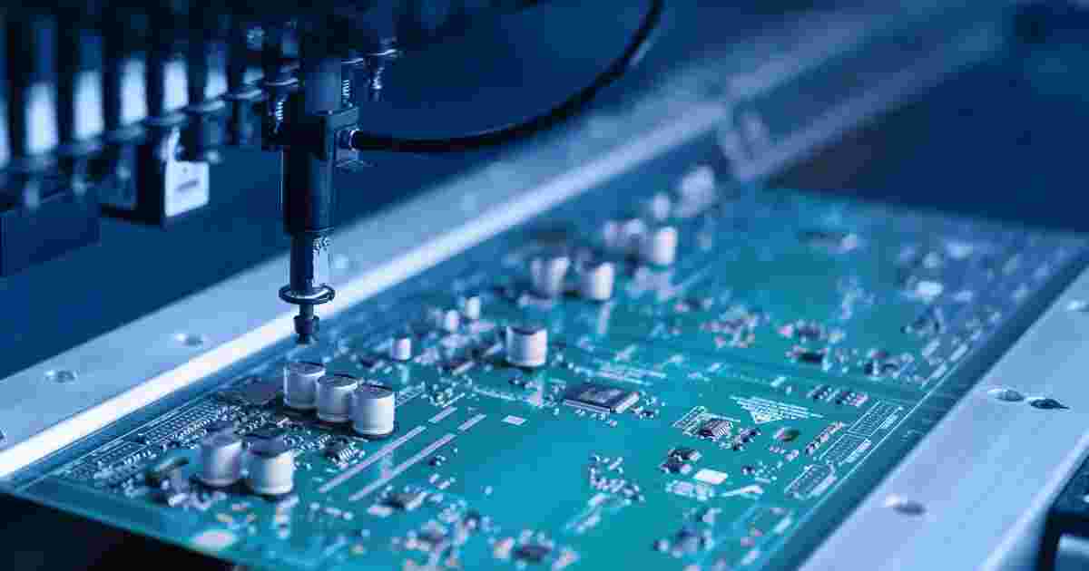
Whether you are a seasoned design engineer, an electronics hobbyist, or a startup preparing for your first manufacturing run, a thorough understanding of how to generate a Pick and Place (PnP) file is critical to your project's success. This file serves as the digital instruction set for automated placement machines, making it an indispensable part of the entire PCB assembly process. This comprehensive guide will detail the technical fundamentals of PnP files, standard formats, and how to export them from nine leading PCB design tools.

What Is a Pick and Place File?
A Pick and Place file, also known as a Centroid File or XY Coordinate File, is a text-based data file that contains the precise location, rotation angle, and layer information for every Surface Mount Device (SMD) on a printed circuit board. Automated SMT (Surface Mount Technology) placement machines directly read this file to achieve high-speed, high-precision component placement.
A standard PnP file typically includes the following key data columns:
- Reference Designator: e.g., R1, C2, U1. This is the unique identifier for each component on the PCB.
- X/Y Coordinates: The exact physical location of the component's center, usually in millimeters (mm).
- Rotation Angle: The component's orientation relative to its default 0-degree orientation in the component library.
- Layer: Indicates whether the component is on the Top or Bottom side of the PCB.
- Component Footprint/Part Number: Provides the component's package information or part number, which is extremely helpful for material verification during PCB assembly.
Common Formats for Pick and Place Files
Most PCB assembly service providers accept files in several standard formats. It is always best practice to confirm the preferred format with your partner before exporting.
.CSV(Comma Separated Values): The most common and recommended format due to its clear structure and ease of review..TXT(Text File): A plain text file using tabs or spaces as delimiters..XY / .CEN(Centroid File): A default centroid file format for some software..POS(Position File): A position file format commonly used by KiCad..XLS / .XLSX(Excel Spreadsheet): Also a very popular and easy-to-edit format.
How to Generate Pick and Place Files in Mainstream CAD Software
1. Altium Designer
- Navigate to
File>Assembly Outputs>Generates Pick and Place Files. - In the dialog box, select
Metric (mm)for units and choose your output format (CSV is recommended). - For a streamlined workflow, use
Output Job Filesto manage all manufacturing files consistently.
2. KiCad
- Open the PCB Editor (Pcbnew).
- Go to
File>Fabrication Outputs>Footprint Position (.pos) File.... - In the settings, choose
CSVas the format and selectMillimetersfor units.
3. Autodesk Eagle
- Open your
.brdboard file. - Run the
ulp/mountsmd.ulpuser language program. - Eagle will generate separate files for the top (.mnt) and bottom (.mnb) layers.
4. OrCAD / Allegro
- Navigate to
File>Export>Placement. - Select the component types you need to export (typically SMDs).
- Configure and export the file.
5. EasyEDA
- In the PCB design interface, click
File>Export>Pick and Place File.... - EasyEDA will directly generate a
.csvfile with all necessary information.
6. DipTrace
- Go to
File>Export>Pick and Place. - Select your format and be sure to set the correct Reference Origin to match your Gerber files.
7. DesignSpark PCB
- Open the PCB layout view.
- Go to
Output>Reports>Component Placement Report. - Save the report as a
.CSVfile and verify the coordinate system.
8. CircuitMaker
- The process is nearly identical to Altium Designer.
- Go to
File>Assembly Outputs>Generates Pick and Place Files.
9. Proteus
- Navigate to
Output>Pick and Place Report. - Configure the output scope, units, and origin before generating the file.

Best Practices for a High-Quality Pick and Place File
- Unified Origin (Zero-Point Origin): Ensure the (0,0) coordinate origin is identical across your PnP, Gerber, and drill files. This is the most critical point.
- Verify Rotation Angles: Check that rotation angles conform to IPC standards to prevent incorrect component orientation during PCB assembly.
- Include Fiducial Marks: For high-precision PCB assembly, including the coordinates of fiducial marks helps the placement machine to calibrate accurately.
- Use Consistent Units: It is strongly recommended to use millimeters (mm) throughout, as this is the global standard for the PCB assembly industry.
- Verify in a Gerber Viewer: Overlay your PnP file with your Gerber layers in a viewer to visually check that every component's position is correct before submission.
- Exclude Non-Placement Parts: Ensure your file does not include DNI (Do Not Install) components, test points, or mounting holes unless specifically required.
More
Generating a correctly formatted and accurate Pick and Place file is the cornerstone of an efficient, error-free PCB assembly process. Its quality is paramount, especially when dealing with high-density or fine-pitch component designs. While modern CAD tools have simplified the export process, investing time in careful validation and review will save significant potential costs and delays on the production line.
Need Professional PCB Assembly Support?
If you're working on a prototype or production run and require reliable, one-stop PCB assembly services, the expert team at Elecrow is here to help.
Please send your design files to our engineering team for a quote and review:
Contact Us: info@elecrow.com
Get an instant quote for your next PCB manufacturing and assembly project today!
