Currency
Toggle Nav


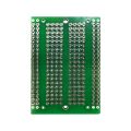
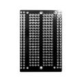
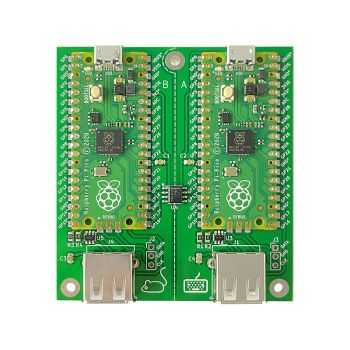
INA219 Current Sensor Module for RASPBERRY PI PICO
$15.00
Availability:
In stock
SKU
CQA231107IN
Weight
46g
Related Products:


×
 Add to cart successfully!


Customers Who View This Item Also Bought
INA219 Current Sensor Module for RASPBERRY PI PICO and PICO2
Frequently Bought Together

INA219 Current Sensor Module for RASPBERRY PI PICO and PICO2
The INA219 Sensor Board is a compact and precise current and power monitoring solution designed for easy integration with the Raspberry Pi Pico, Pico2 and other microcontroller platforms. It is based on the INA219 current sensor IC, a high-side current shunt and power monitor that measures voltage, current, and calculated power through an I²C interface.
This board uses a 0.1 Ω precision shunt resistor, enabling accurate current measurements while maintaining low power dissipation. The I²C address is selectable, allowing multiple boards to be connected on the same I²C bus, making it suitable for multi-channel power monitoring applications.
A MicroPython example program are available for the Raspberry Pi Pico/Pico2, allowing users to quickly read and process bus voltage, current, and power values. The provided software makes integration simple for projects such as battery monitoring, power consumption analysis, embedded systems testing, and laboratory measurements.
Features
- Based on INA219 high-side current and power monitor
- Designed for Raspberry Pi Pico and Pico2
- 0.1 Ω shunt resistor for current measurement
- Measures bus voltage, current, and power
- Selectable I²C address for multiple device operation
- MicroPython library and example code available
- Suitable for power monitoring, battery systems, and embedded projects
Applications
- Battery Monitoring Systems
- Power Consumption Analysis
- Solar Power Systems
- Motor and Actuator Monitoring
- Power Supply Monitoring
- Smart Energy Measurement Projects
- Educational and Laboratory Experiments
Technical Specifications
- Sensor IC: INA219 current sensor IC
- Supply Voltage (VDD): 5.0 V
- Bus Voltage Measurement Range: 0 V – 26 V
- Shunt Voltage Range: ±320 mV
- Current Measurement Range: up to ±3.2 A (with 0.1 Ω shunt resistor)
- ADC Resolution: 12-bit
- Current Resolution: approx. 0.8 mA (with 0.1 Ω shunt)
- Power Measurement: Calculated internally from voltage and current
- Measurement Types: Bus voltage, shunt voltage, current, and power
- Communication Interface: I²C / SMBus compatible
- I²C Speed: up to 3.4 MHz
- Programmable I²C Addresses: up to 16 selectable addresses
- Operating Temperature Range: −40 °C to +125 °C
- Supply Current Consumption: up to 1 mA
- Accuracy: up to ±0.5% (device dependent)
Additional Notes and Information
To run the provided MicroPython example for the INA219 board, install and use the Thonny IDE with your Raspberry Pi Pico.
1. Install Thonny IDE on your computer.
2. Connect the Raspberry Pi Pico to the PC using a USB cable.
3. In Thonny, select MicroPython (Raspberry Pi Pico) as the interpreter.
4. Open the provided `main.py` example file.
5. Save the file to the Raspberry Pi Pico (File → Save As → Raspberry Pi Pico).
6. Press Run (F5) or restart the board.
After uploading, the main.py file will automatically execute on every board reset. The program will initialize the INA219 sensor and display the measured bus voltage, current, and power values in the Thonny terminal
I²C Address Selection
The I²C address of the INA219 current sensor IC can be configured using the A0 and A1 connectors on the board. This allows multiple INA219 modules to operate on the same I²C bus.
Default configuration:
A0 = ON, A1 = ON → I²C address: 0x45
Other address options:
A0 = OFF, A1 = OFF → I²C address: 0x40
A0 = OFF, A1 = ON → I²C address: 0x44
A0 = ON, A1 = OFF → I²C address: 0x41
By changing the A0 and A1 settings, up to four INA219 devices can be used on the same I²C bus.
Important: All devices within the system shall share a common ground (GND) reference to ensure measurement accuracy and proper functionality.
Note: For simplified interfacing and improved accessibility, the use of a 6-pin header connector is recommended.
Downloads
- main.py
- schematics.JPG
- measurement in Shell.JPG
Write Your Own Review
Bestselling Products You May Like


New Products You May Want