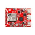
LoRaWAN LR1262 Development Board Integrated RP2040 with 1.8 “ LCD for Long Range Communication (868Mhz/915Mhz)

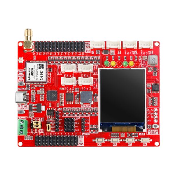
【LoRa LR1262 Dev Board】Onboard 1.8-inch 128*160 SPI-TFT-LCDand uses RP2040 as the main controller, providing more powerful performance;
【Global LoRaWAN and LoRa Frequency Supported】Embedded with the LR1262 module, supports the 868/915MHz frequency band and AT command control;
【Full GPIO and Rich Interfaces】Abundant external interface resources, compatible with Crowtail series modules and other common interface modules on the market.
Description
LoRa technology and Lora devices have been widely used in the field of the Internet of Things (IoT), and more and more people are joining and learning Lora development, making it an indispensable part of the IoT world. This Lora development board uses RP2040 as the main control and is equipped with the LR1262 module that supports Lora and LoRaWAN protocols to help users realize development. RP2040 is a dual-core, high-performance, and low-power ARM Cortex-M0+ architecture chip, suitable for IoT, robots, control, embedded systems, and other application fields. The LR1262 Dev Board is an ultra-low remote transceiver module based on the STM32WLE5CC chip, specially designed for LoRa and LoRaWAN applications.
This LoRaWAN board retains various functional interfaces for development, such as the Crowtail interface, which can adapt to Crowtail module series, the common PIN to PIN header that leads out GPIO ports, and provides 3.3V and 5V outputs, suitable for the development and use of commonly used sensors and electronic modules on the market. In addition, the board also reserves RS485 interface, SPI, I2C, and UART interfaces, which can be compatible with more sensors/modules.
In addition to the basic development interfaces, the board also integrates some commonly used functions, such as a buzzer, a custom button, red-yellow-green three-color indicator lights, and a 1.8-inch SPI interface LCD screen with a resolution of 128*160. We try to minimize the trouble of connecting these components for users when developing and building project prototypes. 
GPIO Pin Definition
|
RP2040 |
LR1262 Development Board |
||
|
GPIO0 |
LR1262-RXD |
GPIO15 |
GPIO15/ Crowtail-D1 |
|
GPIO1 |
LR1262-TXD |
GPIO16 |
LCD-DC |
|
GPIO2 |
GPIO2 |
GPIO17 |
LCD-CS |
|
GPIO3 |
GPIO3 |
GPIO18 |
LCD-SCK |
|
GPIO4 |
Crowtail-UART1-TXD |
GPIO19 |
LCD-DIN |
|
GPIO5 |
Crowtail-UART1-RXD |
GPIO20 |
I2C0-SDA0/Crowtail-I2C-SDA/PCA9555-SDA |
|
GPIO6 |
GPIO6 |
GPIO21 |
I2C0-SCL0/Crowtail-I2C-SCL/ PCA9555-SCL |
|
GPIO7 |
GPIO7 |
GPIO22 |
LCD-RST |
|
GPIO8 |
GPIO8/UART1-TX1/Crowtail-UART1-TX1/485TX |
GPIO23 |
LCD-BLK |
|
GPIO9 |
GPIO9/UART1-RX1Crowtail-UART1-RX1/485RX |
GPIO24 |
485-EN |
|
GPIO10 |
GPIO10/SPI1-SCK |
GPIO25 |
DATA |
|
GPIO11 |
GPIO11/SPI1-MOSI |
GPIO26 |
A0/ Crowtail-A0 |
|
GPIO12 |
GPIO12/SPI1-MISO |
GPIO27 |
A1/ Crowtail-A1 |
|
GPIO13 |
GPIO13/SPI1-CS |
GPIO28 |
BUZZER |
|
GPIO14 |
GPIO14/ Crowtail-D0 |
GPIO29 |
ADC-KEY |
Feature
- Uses RP2040 as the main controller, with two 32-bit ARM Cortex M0+ processor cores (dual-core) ,and provides more powerful performance
- Integrates the LR1262 module supports the 868/915MHz frequency band and AT command control
- Abundant external interface resources, compatible with Crowtail series modules and other commonly interface modules on the market
- Integrates commonly used functionslike buzzer, LED light, LCD display and custom button, making it more concise and convenient when creating projects
- Onboard 1.8-inch 128*160 SPI-TFT-LCD, ST7735S driver chip
- Compatible with Arduino/Micropython, easy to carry out different projects.
Specification
|
Main Chip |
Raspberry Pi chip RP2040, built-in 264KB SRAM, onboard 4MB Flash |
|
Processor |
Dual Core Arm Cortex-M0+ @ 133MHz |
|
TX Power |
+22dBm @Max (LoRa) |
|
RX Sensitivity |
-137dBm @SF12/125kHz |
|
Data Rate |
0.018~62.5Kbps |
|
Modulation |
LoRa/(G)FSK/GMSK |
|
LR1262 Supports frequency band |
850~930MHz (868MHz, 915MHz compatible) |
|
Spreading Factor |
SF5~SF12 |
|
Range |
5~6km, up to 15km max(antenna & environment dependent) |
|
LR1262 Support Interface |
External antenna: SMA or IPEX Gen 1 connector |
|
LCD Display |
Onboard 1.8-inch 128*160SPI-TFT-LCD |
|
LCD Resolution |
128*160 |
|
LCD Driver |
ST7735S (4-wire SPI) |
|
Development environment |
Arduino/Micropython |
|
Interface |
1x RS485 communication interface, 8x 5V Crowtail interfaces (2x analog interfaces, 2xdigital interfaces, 2xUART interfaces, 2xIIC interfaces) 12x 5V universal pin header IO interfaces 14x 3.3V universal pin header IO interfaces 1x 3.3V/5V switchable SPI interface 1x 3.3V/5V switchable UART interface 3x 3.3V/5V switchable IIC interfaces |
|
Buttons and functions |
1x passive buzzer, 4x user-defined buttons, 6x programmable LEDs |
|
Working input voltage |
USB 5V-1A |
|
Operating temperature |
-10°C ~ 65°C |
|
Dimensions |
102mm(L)x77mm(W) |
Package List
- 1x LR1262 Development Board
- 1x Lora Spring Antenna (868Mhz/915Mhz)
- 1x Lora Rubber Antenna (868Mhz/915Mhz)

