
Story
If you're a maker who wants to get eyes on your projects, then presentation is just as important as execution. Great videos and photos are crucial, because most audiences respond more to strong visuals than to technical achievements.
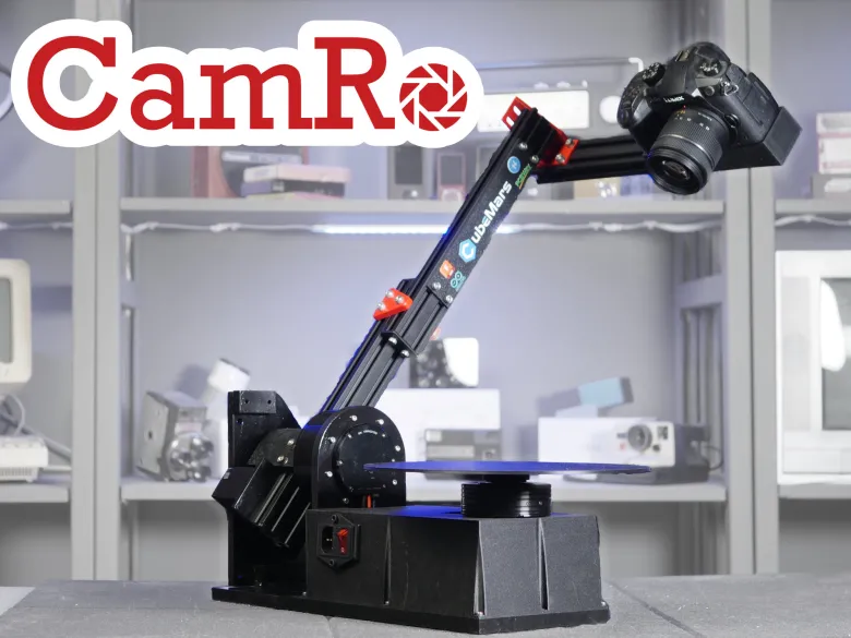
I designed this robot to make it easier to accomplish that!
Check out my video to see it in action:
_cKzsubaMT4.JPG?auto=compress%2Cformat&w=740&h=555&fit=max)
_Gp9CH4JJPr.JPG?auto=compress%2Cformat&w=740&h=555&fit=max)
_lY0wAZqcsB.JPG?auto=compress%2Cformat&w=740&h=555&fit=max)
_41wwJ2R0TP.JPG?auto=compress%2Cformat&w=740&h=555&fit=max)
_SsOhm7vxgW.JPG?auto=compress%2Cformat&w=740&h=555&fit=max)
Overview
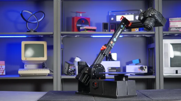
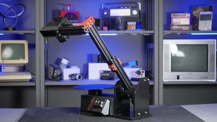
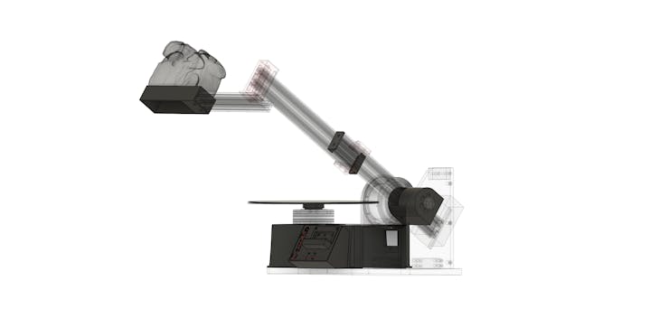
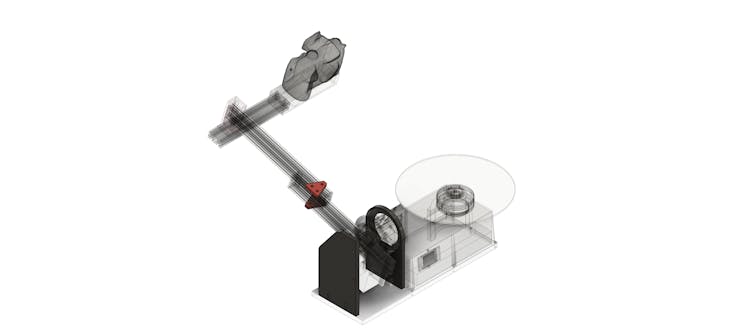
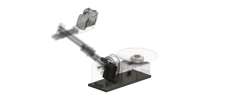
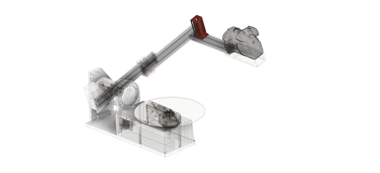
These robot has two degrees of freedom (DoF): a rotating turntable and a pivoting arm. The subject goes on the turntable and the camera mounts onto the arm.
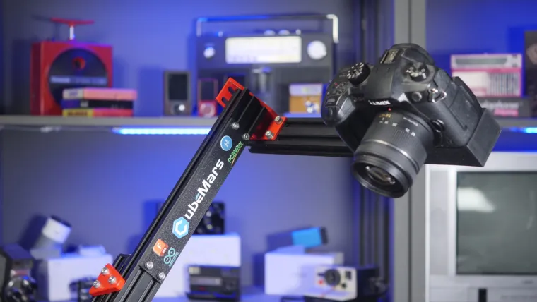
I designed this to be very strong and with very powerful CubeMars actuators, so it can handle heavy DSLR and mirrorless cameras without straining at all. Movement is extremely smooth, resulting in fantastic video quality.
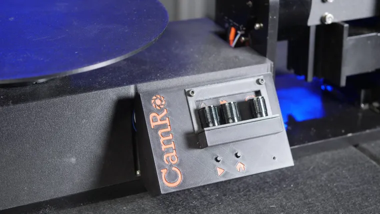
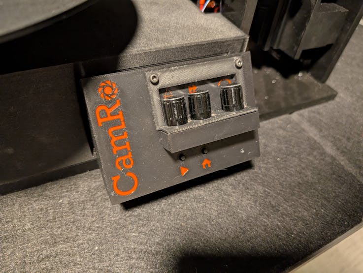
The simple controls let the user quickly adjust arm angle, arm movement speed, table rotation direction, and table rotation speed.
_1uo8vbDnEq.JPG?auto=compress%2Cformat&w=740&h=555&fit=max)
Add in some basic editing (zooming, panning, rotation, speed ramping, etc.) and you can create very dynamic product shots.
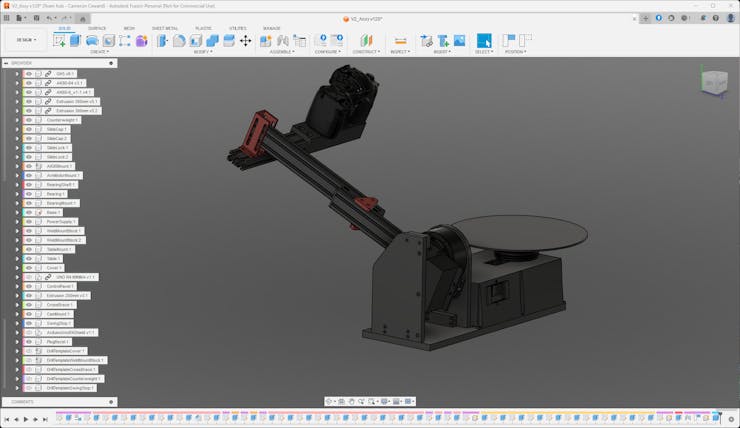
I modeled every part of the arm in Autodesk Fusion 360 as an assembly, so it is easy to modify and to find files. The custom Arduino shield, designed in KiCAD, can be ordered through Elecrow PCB Fab and it has mostly through-hole components for easy soldering.
CamRo is compatible with both the Arduino Uno R4 Minima and Arduino Uno R4 WiFi. Because those have different pins for the CAN bus connection, I designed the PCB so it can work with either (just solder the appropriate bridge).
Fabrication Information
As designed, CamRo requires several different fabrication methods and tools:
- 3D Printing
- CNC Milling
- Manual Milling
- Manual Turning (lathe work)
- MIG Welding
Most of the structural parts are metal—either aluminum or mild steel. That is to make the robot as strong as possible.
However, you could 3D-print all of the parts if you don't have the ability to work with metal. The robot won't be as strong, but that is an option.
Alternatively, you can make use Elecrow's CNC milling service. All of the manually machined parts could also be made with an appropriate CNC mill.
Actuator Information
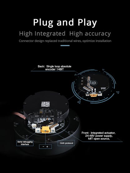
CubeMars supplied the motors for this project and their contribution is the entire reason I started this. The robot uses two of their actuators:
- AK80-64
- Ak60-6
These are, frankly, quite expensive by hobbyist standards—though they're reasonable by professional standards, given their high performance. These are very powerful and precise. Probably overkill for this project, but it is nice that the arm can move even heavy cameras.
It may be possible to use alternative actuators, but I'm not sure.
These are controlled through a CAN bus by the Arduino. When you first set them up, you'll need to use a USB-to-TTL serial cable and the CubeMars Tool software to configure them.
In particular, you need to set the motor IDs to match the Arduino sketch!
3D Print Your Parts
To get started, you'll want to 3D-print your parts. I printed all of mine on a Bambu Lab P1S, upgraded with a diamond nozzle and hardened steel extruder gears.
Those upgrades are important if you're going to use PPA-CF filament, as I did. That filament is great, because it has a nice texture that hides layer lines and is very strong. But it is abrasive, so you shouldn't print it with a normal nozzle and extruder gears.
You can use another filament material if you prefer, but the parts won't be as strong.
This are the parts to print:
The "Slide Cap" and "Table" parts don't need to be very strong, so you can print those in PLA or PETG.
CNC Mill Your Parts
These are the parts that you need to machine on a CNC mill:
The two "Slide Lock" parts are designed to be milled from 1/4" 6061 aluminum plate/bar.
The "Bearing Mount" and "AK80 Mount" parts are designed to be milled from 3/8" 6061 aluminum plate/bar.
_Fq9Khh5Rcc.JPG?auto=compress%2Cformat&w=740&h=555&fit=max)
6061 aluminum is pretty easy to work with and you make these on a fairly light duty mill. Or you can use Elecrow's CNC machining service.
If you make them yourself, take advantage of Autodesk Fusion 360's CAM features! They're very good and you can work directly with the models in the assembly file I provided.
Manually Machine Your Parts
There are several parts that I designed to be milled manually. Several are them are mild steel, which is too tough for my CNC mill—but easy to cut on my big manual mill.
There is also a shaft to support the arm on a bearing. You can turn that on a lathe, using whatever metal you prefer. Mine is brass, because it is what I had on hand.
These are the steel parts you need to manually mill:
_ASedXN7sgq.JPG?auto=compress%2Cformat&w=740&h=555&fit=max)
_DjKLRM54V2.JPG?auto=compress%2Cformat&w=740&h=555&fit=max)
_wzuuspRf3t.JPG?auto=compress%2Cformat&w=740&h=555&fit=max)
I have attached technical drawings for you to work from for all of these parts.
Alternatively, you can use Elecrow's CNC machine service for these, which can handle mild steel without an issue.
The "Cross Brace" part is a special exception:
It is 6061 aluminum, but I milled it manually. I did that because it requires operations in multiple orientations and alignment is difficult when CNC-milling.
_vhTpSGBlsb.JPG?auto=compress%2Cformat&w=740&h=555&fit=max)
Tap Your Holes
Included in the Autodesk Fusion 360 assembly are Drill Template models.
Those are 3D-printable and will help you line mark the screw hole positions, so you can drill them on a drill press (or with a handheld power drill).
After drilling those holes, you can tap them (M3 and M5). I recommend using a high-quality tap set, because the cheap sets break easily and they're very frustrating.
Weld the Base Mounts
You need to weld the two "Base Mount" parts to the "Base" part. Those are mild steel, so MIG welding is ideal.

There is a 3D-printable template in the assembly file to help you position those. Be careful not to weld the outer faces/edges! Doing so would make it so the CNC-milled support parts don't fit properly.
After welding, you can use an angle grinder with a flap disc to the clean up the welds:


Preparation and Paint
You will want to paint all of the metal parts, with the exception of the bearing shaft.
But before you can do that, you need to remove all the grease and grime. Acetone is best for that and you'll want to make sure you're very thorough, scrubbing all the nooks and crannies.
_8Vgs2Gqh8e.JPG?auto=compress%2Cformat&w=740&h=555&fit=max)
Once your parts are clean, you can spray them with primer. Use whatever brand you prefer, but I recommend a self-etching primer.
_jG73jM4sJC.JPG?auto=compress%2Cformat&w=740&h=555&fit=max)
Give them several coats and sand them with progressively finer sandpaper, until you get a smooth finish.
_KnNiSM6yB7.JPG?auto=compress%2Cformat&w=740&h=555&fit=max)
Then you can apply coats of whatever paint you prefer.
_WeGI3I9e71.JPG?auto=compress%2Cformat&w=740&h=555&fit=max)
Once again, you'll want to sand to get a smooth finish—ideally ending with wet sanding.
Assemble the Arduino Shield
Once you receive your PCB and get your components, you can populate the shield.
_lz005b1ziL.JPG?auto=compress%2Cformat&w=740&h=555&fit=max)
That's pretty straightforward, as it uses through-hole components that are easy to solder. There is one exception: the WS2812b LED used to indicate the robot's status. That is a surface-mount component, which is a bit trickier to solder.
You can either order a bare WS2812b LED or scavenge one from an LED strip. Then you can use a soldering iron to put it on the board—a hot air gun, hot plate, or oven isn't necessary.
_UnsUgdleOl.JPG?auto=compress%2Cformat&w=740&h=555&fit=max)
Pay attention to the orientation! The cut-off corner should face in the direction shown.
Solder the bridge! The Arduino Uno R4 Minima uses different pins for the CAN connection compared to the Arduino Uno R4 WiFi. This solder bridge makes it so the same shield works with both. Just solder across the side for the Arduino you're using.
_wrty1AZnar.JPG?auto=compress%2Cformat&w=740&h=555&fit=max)
From there, solder the potentiometers, the buttons, the pin headers, and the CAN transceiver pins.
_DG4iqmn31S.JPG?auto=compress%2Cformat&w=740&h=555&fit=max)
Configure Motors and Flash Arduino
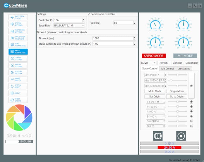
Before you can use the CubeMars actuators, you need to configure them. To do that, you need the CubeMars Tool software on your PC and the USB-to-TTL serial cable.

Set the Controller ID, the Baud Rate, and the Rate (Hz).
My code assumes the Arm Motor's Controller ID is 106 and the Table Motor's Controller ID is 107.
You can set Timeout parameters if you like. But as far as I can tell, that function doesn't actually work.
---------------------------
Next, you can flash the provided Arduino sketch to your Arduino in the normal way.
I have thoroughly commented the code in the sketch if you'd like to understand how it works or make any modifications.
Assemble the Robot
You need to assemble the parts in the proper order for everything to fit together.
Start by attaching the AK80Mount to the Base using M5 screws:
_vtai2r8kUi.JPG?auto=compress%2Cformat&w=740&h=555&fit=max)
Then use M3 screws to attach the AK80-64 Actuator to the AK80Mount:
_MqPRjxQmST.JPG?auto=compress%2Cformat&w=740&h=555&fit=max)
Use M4 screws to attach the ArmMotorMount to the AK80-64 Actuator:
_X0Ty2jcC5X.JPG?auto=compress%2Cformat&w=740&h=555&fit=max)
Put the 608ZZ Bearing into the BearingMount and the BearingShaft into the ArmMotorMount:
_DxyLyV5H5Z.JPG?auto=compress%2Cformat&w=740&h=555&fit=max)
Use M5 screws to attach the BearingMount to the Base:

Use M5 screws and T-nuts to attach a 300mm length of Aluminum Extrusion to the ArmMotorMount:
_sm6Cxe9GsT.JPG?auto=compress%2Cformat&w=740&h=555&fit=max)
Use M5 screws and T-nuts to attach the Counterweight to the Aluminum Extrusion:
_1nUNI8OAkt.JPG?auto=compress%2Cformat&w=740&h=555&fit=max)
Use M5 screws to attach the SlideCap parts to the ends of the two 300mm Aluminum Extrusions:
_4RXCASahtt.JPG?auto=compress%2Cformat&w=740&h=555&fit=max)
Use M5 screws and T-nuts to attach the SlideLock parts to the two 300mm Aluminum Extrusions:
_pw00FOkvyu.JPG?auto=compress%2Cformat&w=740&h=555&fit=max)
Attach the 200mm Aluminum Extrusion to the 300mm Aluminum Extrusion using the Cross Brace, M5 screws, and T-nuts:
_eTgv1tg8bC.JPG?auto=compress%2Cformat&w=740&h=555&fit=max)
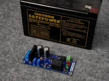
Attach the Power Supply to the Base using M3 screws:
_NZtOjBY3RM.JPG?auto=compress%2Cformat&w=740&h=555&fit=max)
Attach the AK60-6 Actuator to the Cover using M3 screws:
_PFByMb5Ywv.JPG?auto=compress%2Cformat&w=740&h=555&fit=max)
Attach the Outlet using the supplied screws and PlugBezel:
_8r1wEPv3Zi.JPG?auto=compress%2Cformat&w=740&h=555&fit=max)
Attach the TableMount to the AK60-6 Actuator using M3 screws:
_5pttRIXTXO.JPG?auto=compress%2Cformat&w=740&h=555&fit=max)
Place the Cover on the Base, but don't put in the screws yet (you need to add the wiring before you do that):
_rBdSm9bfLM.JPG?auto=compress%2Cformat&w=740&h=555&fit=max)
Place the Table on the TableMount. It is just press/friction fit:
_mD3ceOx9eg.JPG?auto=compress%2Cformat&w=740&h=555&fit=max)
Use M5 screws to attach the SwingStop to the BearingMount:
_bvQdiPtVR1.JPG?auto=compress%2Cformat&w=740&h=555&fit=max)
Use M5 screws and T-nuts to attach the CameraMount to the 200mm Aluminum Extrusion:
_28qYgkLLyB.JPG?auto=compress%2Cformat&w=740&h=555&fit=max)
That's it for the main assembly! But you still need to finish up the wiring and add the control panel...
Wiring and Final Assembly
There are only a few things left to do to finish everything up.
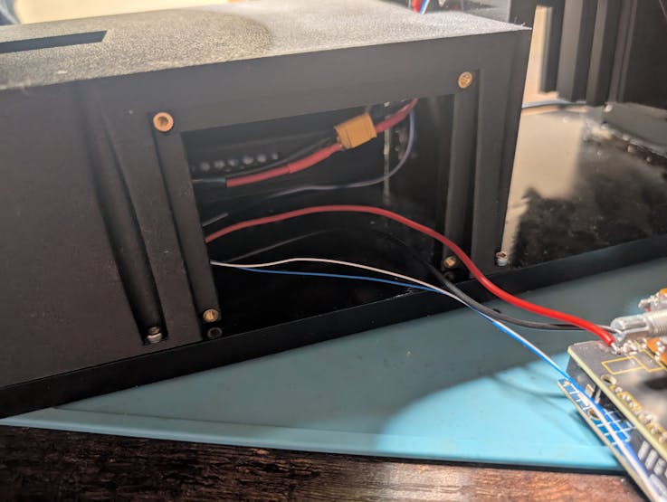
First, connect power cables between the Outlet and the Power Supply. And between the Power Supply and Actuators, as well as the Power Supply and Shield:

Then, connect the CAN wires (supplied by CubeMars with the actuators) from the Shield daisy-chained to the two Actuators:

After that, use M3 screws to attach the Cover to the Base.
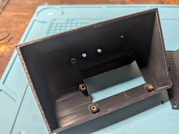
Next, you need to use a soldering iron (or a dedicated tool) to put M3 heat set inserts into the Cover, the ControlPanel, and the ControlPanelCover:
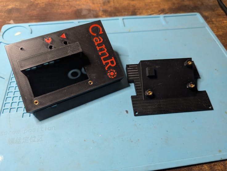
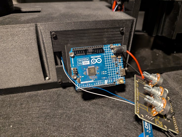
Next, use M3 screws to attach the Arduino Uno R4 to the ControlPanel (without the Shield) and attached the ControlPanel to the Cover:
Use M3 screws to attach the Shield to the ControlPanelCover:
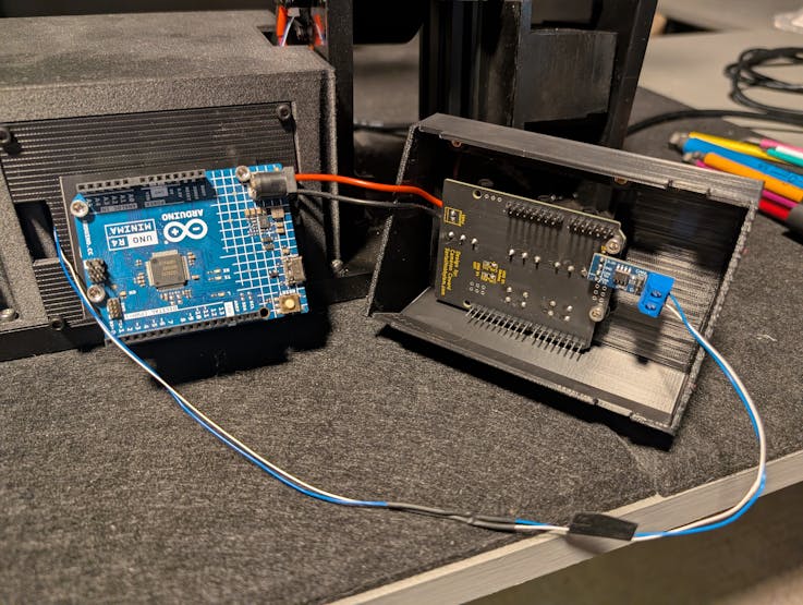
Tuck the wires inside the Cover, then attach the Shield to the Arduino Uno R4 (connect the pin headers):
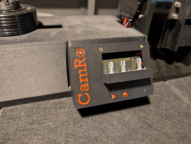
Use M3 Screws to attach the PotCover and put on the Potentiometer Knobs:
Now you're done!
Use CamRo
I designed the controls to be intuitive to use, but here is a brief overview:
1. Switch on power (the outlet on the back).
2. The Status LED should be Red, indicating that you need to home the robot. Push the Home button.
3. After the arm moves through the homing process, the Status LED should change to Green, indicating it is ready.
4. The far-left knob adjusts the angle that the arm swings to before moving back. The knob next to that adjusts the arm movement speed.
5. The far-right knob adjusts the both the turntable rotation direction and speed. Center it and it won't move. The further counter-clockwise you turn it, the faster the table rotates counter-clockwise (and vice-versa).
6. Press the Start (Play) button to begin the movement.
7. If you want to cancel the movement early, press Start again.


Enjoy!