Story
Constant current generator for LEDs
Circuit description
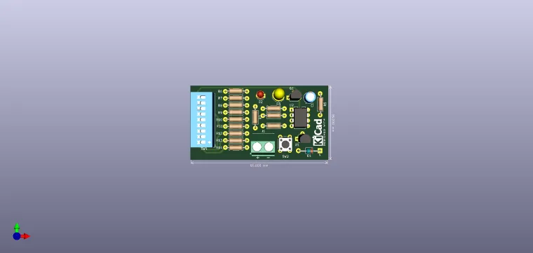
The proposed scheme was developed around an LM358 operational double-amplifier integrated circuit. The constant current generator is made with the help of the U2B amplifier, which has at the non-inverting input (pin 5) a precision voltage reference (integrated circuit TL431) with the typical value of 2.495V, temperature compensated. the U2B leash controls the transistor Q1 whose collector will obtain the constant current with which the LEDs will be tested, and whose emitter is connected to the reversing input of the U2B amplifier, and by means of a ground resistor. Considering the differential input voltage zero, so the voltage at the reversing input (pin 6 LM358) will be equal to the voltage at the non-reversing input (pin 5 LM358). By imposing the desired Ic current and knowing the reference voltage, the values ??of the resistors result immediately.
The selection of a desired LED current is made via the micro switch.
The values ??0.5, 1 and 2mA are used for ultra-bright LEDs with a maximum current of 2mA, the values ??3, 5, 10mA for normal LEDs, and the values ??15 and 20 mA are useful for older LEDs , low efficiency. By mounting a voltmeter at the LED terminals and changing the current, the direct static characteristic of the LED under test can be obtained. The U2A operational amplifier, of the LM358 integrated circuit, is used as a voltage comparator that detects the discharge of the mounting power supply battery. It is recommended to supply a 9V battery. On the inverter input (pin 2), U2A has applied the reference voltage supplied by circuits TL431, and on the non-inverting input (pin 3) a voltage supplied by a resistive divider connected to the terminals of the power supply. When the voltage at the non-inverting input drops below the reference voltage, the U2A output becomes 0 logic, the LED labeled "LOW BAT" lights up indicating the discharge of the power supply battery and at the same time the decrease of the current imposed by the LED, the constant current generator coming out normal operating parameters. With the values ??from the diagram for the resistive divider, and taking into account the presence of diode D1 (mounted in the circuit for mounting protection in case of voltage supply with changed polarity) at the terminals of which we have a voltage drop of about 0.6V, the notification threshold results. of the battery discharge is about 5.6V.
Resistor R1 imposes the current through the TL431 circuit and its value has been chosen so that at the minimum supply voltage of 5.6V the current is at least 1 rnA (value recommended in the catalog data of the TL431 circuit for a correct stabilization). The value of 2.7k was chosen to take into account the bias currents of the LM358 integrated circuit inputs. Considering that the assembly consumes current even in the absence of the tested LED (it is the polarization current of the TL431 circuit, the current through the resistive divider and the supply current of the LM358 circuit), it was chosen to connect the assembly to the supply voltage via push - button.
-
- 0,5mA 5k 4.7k+270R
- 1mA 2k5 2,4k+100R
- 2mA 1k25 1,2k+51R
- 3mA 833R 820R+10R
- 5mA 500R 470R+27R
- 7.5mA 333R 330R+3.3R
- 10mA 250R 240R+10R
- 15mA 166R 120R+47R
- 20mA 125R 120R+4,7R
Have fun with it !


