
Story
Project Overview
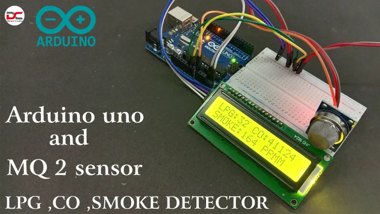
This DIY electronics project demonstrates how to build an air/gas quality monitoring system using an Arduino, an MQ‑2 gas sensor, and an I2C LCD display. The setup detects gas concentrations such as LPG, CO, and smoke, and continuously displays real‑time levels on the LCD.
Objectives
-
Interface the analog MQ‑2 gas sensor with Arduino
-
Read analog sensor values representing gas concentration
-
Display sensor readings in real‑time on an I2C LCD module
-
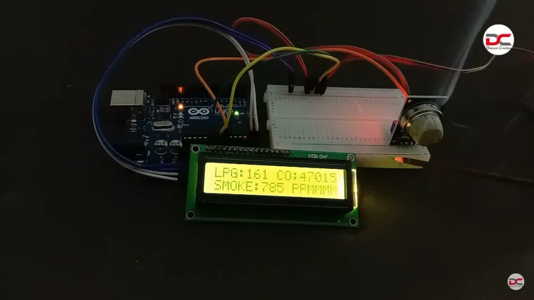
Alert users if gas concentrations exceed defined thresholds
Key Components
| Component | Description |
|---|---|
| Arduino Uno / Nano | Main microcontroller |
| MQ‑2 Gas Sensor | Detects LPG, CO, smoke, butane, methane, etc. |
| I2C LCD Display (16×2) | Simplifies wiring via two-wire SDA/SCL bus |
| Potentiometer | Adjust LCD contrast |
| Jumper Wires / Breadboard | For prototyping |
| Optional Buzzer / LEDs | For visual/sound warning alerts |
System Workflow
-
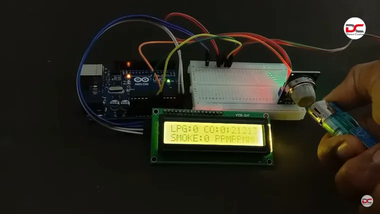
MQ‑2 sensor outputs an analog voltage proportional to gas concentration.
-
Arduino reads that via analog input pin (e.g. A0).
-
The code maps sensor voltage into gas concentration units or raw values.
-
Data is sent via I²C protocol to the LCD, updating live readings.
-
If levels cross a safety threshold:
-
Display warning text on LCD (e.g. “Gas Detected!”)
-
(Optional) Trigger buzzer or LED alerts.
-
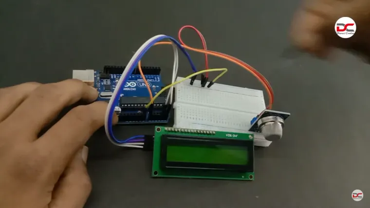
Circuit Connections
Sensor Wiring:
-
VCC → Arduino 5V
-
GND → Arduino GND
-
AOUT → Arduino Analog Pin A0
I2C LCD Wiring:
-
SDA → Arduino A4 (Uno) or board-appropriate pin
-
SCL → Arduino A5 (Uno) or board-specific pin
-
VCC → 5V
-
GND → GND
Use a 5 KΩ potentiometer connected between VCC, VO (LCD contrast pin), and GND to adjust display contrast.
Applications & Extensions
-
Home gas leak detection or safety warning system
-
Real-time environmental monitoring of kitchen or garage zones
-
Easily extendable with buzzer alarms, OLED screens, or colors LED arrays
-
Capture and log data to an SD card or cloud service (via ESP modules)
-
Advanced mapping of raw analog values to actual ppm gas concentration using calibration curves and datasheets
Learning Outcomes
-
Working with analog gas sensors (MQ series)
-
Implementing I2C communication for display modules
-
Real-time data monitoring with Arduino
-
Sensor calibration and alert threshold design
Safety & Calibration Notes
-
MQ‑2 sensors are sensitive to multiple combustible gases and smoke—output may vary; perform calibration if specific accuracy is needed.
-
Allow a warm-up time (~2 minutes) before readings stabilize.
-
Avoid direct exposure to liquid streams or strong gas sources.
-
This is a hobby-grade system only—do not rely on it for professional or life-critical safety.
Summary Table
| Feature | Description |
|---|---|
| Sensor Type | MQ‑2 – LPG, CO, smoke detection |
| Display | I²C LCD (typically 16×2 characters) |
| Read Method | Analog (A0) with I²C update on LCD |
| Calibration | Threshold-based; map raw analog values |
| Extension Potential | Buzzer, LEDs, IoT logging, data alerts |