Story
Control Pulse Width Modulation with NE556
PWM modulation
Introduction
PWM, (Pulse Width Modulation) is the most efficient way to control analog circuits using digital outputs, by
changing the duration and frequency of the signal.
What does a rectangular signal look like?
What can we change about this signal?
The duration of each state t1 and t2, so the fill factor, where T= t1 + t2 = constant. If only one of the times (t1 or t2) is varied
then the period T of a cycle varies, so the frequency f=1/T varies.
From the image above it can be seen that the PWM signal is actually a rectangular signal modulated in duration by
changing the duration of each period t1, t2 of the cycle as well as possibly changing the frequency. Both parameters will be explained in
the following. The clock cycle frequency is measured in Hz and the fill factor is measured in percentage values (%).
The amplitude of the output signal is constant even if the amplitude of some signals that produce the change of the factor of
filling varies.
Clock cycle and fill factor parameters
The first parameter is easy to understand, it is the total duration of the repetitive signal with the duration t1 representing the time as long as the signal
the duration t2 is also positive, which represents the time the signal stays at logic level 0, after which a new cycle begins. The cycle time is
so: T= t1 + t2
Looking at the signals below we notice that the sum of the two periods is constant even though t1 and t2 vary.
We will call the ratio t1/Tx100 the duty cycle.
We observe that the period of a cycle is constant. According to the formula below:
Period (P) = 1 / Frequency (f)
the period of a cycle is inversely proportional to the frequency. So in the example above:
- the frequency is constant, although the periods t1 and t2 are variable, since their sum is constant.
- the filling factor is the percentage value of the duration of time, while the signal has a positive value, of the total duration of a cycle complete.
Features:
· Control voltage: 8-18Vdc
· Load voltage: 8-90Vdc
· Maximum power: 40W
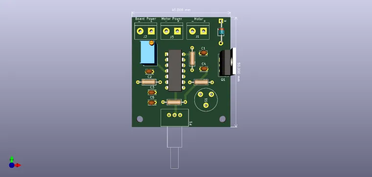
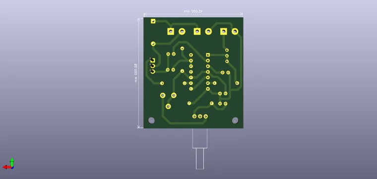
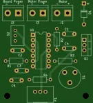
Circuit presentation
With this type of circuit you can control the speed of a
motor from 0 to 100%, keeping the torque constant. In principle
the first astable in the NE556 circuit generates a signal with
the frequency of 400Hz which applies to a monostable whose
period is determined by the value of the potentiometer R9.
From R8 the excess period, called CUTOFF, is fine-tuned.
Both N-channel and transistor transistors can be used
channel P, except that in this case the load is between
source and mass of force (masses do not couple to each other) and
the drain is connected to + 12V where the extra voltage is also connected to
force.
P.S. I am not the original author of this circuit, I just draw it.


