
Story
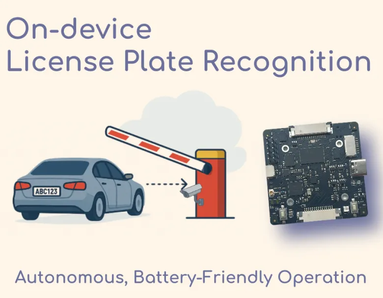
Gate is an open-source smart gate controller that automatically recognizes vehicle license plates to grant access – all without any cloud connection.
It’s built around a compact AI camera module that can work entirely offline and even run on batteries, making installation as simple as mounting the device by your gate and turning it on.
Gate combines plug-and-play simplicity with powerful on-device AI: just attach a camera, flash the provided firmware, and you have a functional license-plate triggered gate opener. This means no monthly fees, no internet setup, and no complicated wiring into your existing gate system.
Gate in a Nutshell
-
Beginner-friendly, yet deep: Works out of the box, but offers full customization for advanced users.
-
Standalone solution: Manage license plates via smartphone; the gate opens automatically for known vehicles.
-
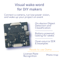
Customizable AI: Swap the model to detect other objects or integrate it into home automation.
-
Efficient hardware: Powered by HX6538 (Cortex-M55 + Ethos-U NPU) + nRF52833 for connectivity.
-
Battery-capable & offline: Runs without internet or cloud; supports off-grid use with low power draw.
-
Private & fast: All video processed on-device — no data leaks, no latency.
-
Open-source: Learn, adapt, and extend to your vision projects.
How It Works
Gate’s magic comes from a two-brain architecture working in tandem on a single module:
-
Vision Processor (Himax HX6538 MCU): This is a specialized microcontroller with a built-in AI accelerator (Arm Ethos-U55). It handles the heavy lifting of computer vision. When active, it captures an image from the connected camera and runs two tiny neural networks in sequence. First, a License Plate Detection (LPD) model finds the location of any license plate in the image. Then, a License Plate Recognition (LPR) model reads the characters on the plate from that cropped region. Both models run completely on-device on this MCU, so no internet or external processing is needed. Once the Vision MCU decodes the plate number, it hands the result to the second “brain.”
-
Control & Communication Processor (NordicnRF52833 MCU): This is a low-power microcontroller that serves as the system's manager. Most of the time, the nRF52833 is the only chip powered on – it monitors sensors and handles communication. It uses a built-in Time-of-Flight (ToF) distance sensor to detect if a vehicle (or any object) is approaching the gate. If the ToF sensor signals movement in front of the camera, the nRF wakes up the Vision MCU by providing it power. After the Vision MCU does its plate recognition job, the nRF receives the recognized number and checks it against a stored “whitelist” of authorized plate numbers (which you can configure). If there’s a match, the nRF triggers the gate to open. It does this by sending a signal out through one of its output pins.
Low-Power Cycle: The Gate is designed to spend most of its time asleep to conserve energy. The workflow cycle is as follows:
-
Standby: The device is sleeping to save power. Only the nRF52833 is awake in a very low-power mode, periodically pinging the ToF distance sensor. Everything else, including the camera and vision processor, is unpowered to preserve battery.
-
Detection (Wake-up): A car comes into view near the gate. The ToF sensor notices an object within its set range. The nRF52833 then powers on the Vision MCU and camera.
-
Recognition: The Vision MCU (HX6538) boots up (in 50 milliseconds) and grabs an image from the camera. It runs the plate detection model, finds a plate, then runs the recognition model to read the plate’s characters. Let’s say it reads “51AB123”. It sends that text result back to the nRF.
-
Decision: The nRF checks if “51AB123” is in its list of allowed numbers (the whitelist). If yes (authorized vehicle), it proceeds to unlock the gate. If not, it ignores the event (or could log it as an attempt).
-
Gate Trigger: To open the gate, Gate uses a clever hack: instead of interfacing directly with the gate’s control board (which can be complex or void warranties), it mimics a remote button press. The nRF activates an output pin on the module that is wired to a simple transistor switch. That switch is connected to a radio transmitter (or even soldered across the contacts of a spare gate remote’s button). In effect, the device “presses the remote button” for you when an authorized plate is seen. The gate’s receiver then opens the barrier as if you clicked your remote. This approach means Gate can integrate with virtually any gate system that uses a wireless fob—no need to modify the gate’s electronics at all.
-
Sleep again: After the action, the nRF cuts power to the Vision MCU and camera. The system returns to standby, with only the nRF and sensors idling. It’s ready for the next car, all while potentially running on a battery for long periods.

This offline, on-device processing means the system is fast (no round-trip to a server), private (images are not sent anywhere), and reliable(works even in remote areas with no internet). In our tests, the recognition and trigger happen almost instantly after a car stops at the gate. And thanks to the low-power design, GateBox can be powered by a battery pack — you could even add a solar charger to make a completely self-sufficient installation.In fact, with a standard 2500 mAh battery, the system can run for over 30 days (or 2, 500+ hours) even under relatively high traffic — up to 5 cars per hour, every day.
Android App
Gate includes an open-source Android app for managing the system over Bluetooth. You’ll be able to add or remove license plates, preview the camera feed during setup, and configure key settings — all without cables, Wi‑Fi, or a PC.The app is still under development, and not all features listed above are currently available.Since the source code is fully open, you can modify the app freely to suit your specific use case or integrate it into a larger system.


What You Need
Before building your Gate, let’s gather the components and toolsrequired. The project uses readily available hardware and open-source software.
Hardware Components:
-
Grovety Smart Vision Module– This is the core development board that includes the Himax HX6538 AI MCU and Nordic nRF52833 MCU on one board. It has connectors for camera, USB, and expansion pins.
-
Raspberry Pi Camera Module (v2) – or any compatible MIPI CSI camera) serves as the vision sensor. This plugs into the vision module’s camera connector. You’ll also need the camera ribbon cable to connect it (usually comes with the camera).
-
Barrier Gate Remote Control or RF Module – You’ll need a way to interface with your gate. Easiest is to use a spare wireless remote that works with your gate’s motor. We will effectively wire Gate’s output into this remote’s button. Alternatively, you can use an RF transmitter module that matches your gate’s frequency/protocol, but using a premade remote is simpler (no need to encode signals if you just simulate a button press).
-
USB-C Cable – Used to power the board and to program the nRF52833 via USB. The Grovety module has a USB-C port (J8) for this purpose.
-
Power Source – During development, you can power the board via USB. For deployment, you might use a 5V DC supply or a battery. For battery operation, a USB power bank or a 3.7V Li-ion battery with a step-up converter to 5V could work (the nRF52833 also manages battery charging if a Li-Po is connected to the board’s power pins, since the board is designed for portable use).
-
(Optional)Mounting Hardware: To set up the system by your gate, you’ll eventually want an enclosure or mount. In the prototype stage, a simple acrylic stand was used to hold the board and camera in place. Ultimately, you might fit everything into a weatherproof outdoor camera casing for permanent installation.
Software and Tools:
-
Gate Firmware and Model Files – Download the pre-built firmware binaries and neural network model files from the project’s GitHub repository. These include the firmware for the nRF52833 (Gate controller) and the firmware + ML models for the Himax HX6538 (plate detector/recognizer). All are provided so you typically don’t need to compile anything.
-
Python 3.10+ – A Python runtime is needed on your computer to run the utility scripts (for testing and configuring Gate). You’ll also need to install a few Python packages (such as PyQt5 for the GUI, etc.). See the repository for the list of dependencies and a requirements file.
-
mcumgr (MCU Manager) – This is a command-line tool used to flash the nRF52833’s Zephyr firmware using the SMP protocol. It’s part of the Apache Zephyr project. You can install it via pip (pip install intelhex pyserial mcumgr) or use the pre-compiled binaries. (Alternatively, the project provides a batch file that invokes mcumgr, simplifying the process.)
-
Serial Terminal Software (optional) – If you want to manually interface with the device (for debugging or sending commands), a serial terminal program like PuTTY, TeraTerm, or even the built-in terminal in Arduino IDE can be handy. This isn’t required for normal operation, but useful for advanced tinkering.
-
Gate Mobile App (Android, optional) – An Android app is under development for Gate. At the moment, it allows you to connect to the device (via Bluetooth Low Energy) to view the camera’s image, see the event history, and adjust settings like the ToF sensor’s range. While it’s not strictly needed, it can make configuration easier once you deploy the device at the gate. (Check the project page or repository for links to the app or APK download.)
With these components and tools in hand, you’re ready to build your Gate!
Build Steps
Building Gate is straightforward. The hardware assembly involves just a couple of connections, and the software setup is guided by provided scripts. We’ll go through the process step by step.
Familiarize with the Board: Locate the key buttons and ports on the module – this will help during firmware flashing:
-
SW1 and SW2 – These are push buttons used for entering bootloader/programming modes.
-
J8 (USB-C port) – This is the main USB connector for power and for programming the nRF52833 MCU. You’ll use this to power the board from your PC and to upload firmware to the nRF.
-
J2 (10-pin header) – This is where you connect the USB-to-UART adapter to program the Himax HX6538 MCU. The pins are typically labeled; you will at least need to connect TX, RX, 3.3V, and GND from your adapter to the corresponding pins on J2. (Refer to documentation for the exact pinout; for example, pin 1 on J2 might be the RX input to the Himax, etc.)
-
Indicator LEDs – The board likely has LEDs that indicate status (power, activity, etc.). For instance, an LED might blink to show when the Himax MCU is in bootloader mode. It’s good to note their behavior (the original text mentions a red LED blinking when the Himax is ready to be flashed, and blue/red toggling when running).
-
Any other connectors – If you plan to use a battery, identify the battery connector or VIN pins. Also, identify the output pin that you will use to trigger your gate remote (the documentation or schematic can guide you; it might be a GPIO pin on an exposed header which goes HIGH to simulate the button press).

1. Hardware Assembly and Setup
Connect the Camera: Take your Raspberry Pi Camera Module and attach the ribbon cable to it if not already attached. On the camera board’s connector, carefully lift the small latch, insert the ribbon cable (metal contacts facing the correct way, usually toward the PCB), and press the latch back down to secure it. Next, connect the other end of the ribbon cable to the camera connector (J5) on the Gate main module. J5 is a small MIPI CSI-2 slot on the board. Lift its latch, insert the ribbon (ensure the orientation is correct – on the Grovety board, the blue side of the ribbon faces toward the board’s edge or a marking indicating “up”), and lock the latch. Now your camera is physically attached to the AI module.

At this point, the hardware is assembled. The camera and board should be connected, and the board is ready to be powered/programmed. You can optionally mount the hardware on a makeshift stand or enclosure for convenience. In our build, we screwed the board and camera onto a laser-cut acrylic stand using standard M2.5 standoffs. This isn’t necessary, but it helps to have the camera stable and aimed correctly during testing.

Ultimately, you might install Gate in a proper outdoor housing (like a CCTV camera casing) for weather protection, but for now, a temporary setup is fine.

2. Flashing the Firmware
Gate requires uploading firmware to two microcontrollers: the nRF52833 (the controller MCU) and the Himax HX6538 (the vision MCU). We’ve provided pre-compiled firmware binaries and handy scripts to make this as easy as possible – you won’t be writing any code here, just executing the upload tools. Note:If you’re not interested in the nitty-gritty, you can find detailed flashing instructions in the project repository’s README. What follows is a summary:
A. Program the nRF52833 (Controller MCU):The nRF52833 runs a firmware based on Zephyr RTOS that controls device operation and communication. We’ll use the mcumgr tool to upload this firmware via USB.
-
Enter Bootloader Mode: Ensure the board is disconnected from USB. Press and hold SW2, then plug the USB-C cable into J8 (connecting to your PC). After a few seconds, release SW2. This puts the nRF into DFU (Device Firmware Upgrade) mode. Your computer should detect a new USB device or COM port enumerated by the bootloader.
-
Upload Firmware using mcumgr: We’ve provided a script called nrf/mcumgr_run.bat (for Windows; there’s an equivalent command for Linux/macOS) that invokes mcumgr with the correct parameters. Open this script in a text editor and update the COM port number to match the one your PC assigned (check Device Manager or dmesg logs for the COM/tty name). Then run the script. It will automatically transfer the Zephyr firmware to the nRF. Within a few seconds, you should see a success message. Once done, the nRF52833 will reboot into the new firmware.

That’s it for the nRF – it now has the “brains” of Gate loaded (managing sensor, Bluetooth, whitelist logic, etc.).
B. Program the Himax HX6538 (Vision MCU)
✅ Step 1 — Enter bootloader mode
· Connect the board to your PC via USB-C.
· Hold SW2 until the red LED starts blinking, then release the button.
✅ Step 2 — Configure the flashing script
· Open himax/prog-all-gb.bat in a text editor.
· Replace the COM port number with the one assigned to your board after connecting the USB-to-Serial adapter.
· Save the file and run it.
✅ Step 3 — Flash the firmware
· Follow the console prompts. The script will open multiple console windows to flash each model and the main firmware.
· When prompted, press and release SW1 on the board.
· After each part finishes, close the child console window to let the main script continue.
· Repeat until all parts are flashed. The last stage installs the main working firmware.
⚠️ TroubleshootingIf the COM port does not appear:
· Disconnect the USB-C cable from the board.
· Flip the connector and plug it back in while holding SW2.
· Release SW2 once the red LED starts blinking.
· Repeat Step 2–3.
3. Testing and Demo
With the hardware assembled and firmware installed, it’s time to see Gate in action. In this phase, we’ll use the provided Python GUI to test the system’s functionality in a controlled way before hooking it to the actual gate hardware.
Connect and Configure PC Interface:
-
Keep the board connected to your PC via USB (this powers the device and also allows the PC to communicate with the nRF52833 over a serial port). The nRF firmware exposes a serial API that the Python scripts will use.
-
In the project’s software files, locate python/interfaces/serial_wrapper.py. Open it in a text editor and find the line (around line 7) where the COM port is specified. Change it to the port name that your Gate board enumerated as (on Windows it might be something like COM3, on Linux a /dev/ttyACM0 or similar). Save the file.
-
Now run the script python/image_reader_sr.py. This will launch a simple Gate GUI on your computer. A window should appear showing a blank or static image area (which will soon display camera feed) and some controls. If everything is set up correctly, within a few seconds you might start seeing live video from the Gate camera in that window! If you don’t see video immediately, there are checkboxes for “Update camera” or similar – ensure they are checked to stream the camera feed.

View Recognition Results: Point the camera at a car’s license plate. If you don’t have a car handy, even a printed photo or an image of a license plate on your monitor will do – the system should detect it. When a license plate is in view, you should see the recognition result appear in the “history” text box on the GUI, typically as the alphanumeric plate text along with a confidence or timestamp. For example, it might list “[12:34:56] Plate detected: 51AB123”. This confirms that the Vision MCU is doing its job and the result is being passed to the PC interface.

Whitelist a Plate: Initially, your whitelist of authorized plates is probably empty or set to a default test number. To add a plate to the allow-list (so that Gate would trigger the gate for it), use the GUI’s controls: there’s usually an input box labeled for adding a number. Enter the license number (e.g., 51AB123 or whatever format your plates are) in the text field at the bottom-right of the GUI and click the “Add” or plus button. This sends a command to the nRF to store that number in its memory as an authorized plate. The GUI may update to show it in a list of stored numbers.

Now, whenever that plate is recognized, the system knows it should open the gate. You can test this logic in the simulation by observing an indication for “access granted” – in the GUI it might simply log something, but on the device hardware, you might also see an LED or the output pin toggling (hard to notice without equipment, but if your remote is connected, maybe the remote’s LED lights up).
The included license plate recognition model is optimized for a specific format: one letter, three digits, two letters, and two region digits. You can test the system using the sample images provided in the repository.If your local plates use a different format, you may need to replace the neural network with a model trained specifically for your region.We will publish a guide on how to swap the model — whether for your local license plate format or entirely different objects — [link coming soon].
Autonomous Mode Test: The Python GUI continuously communicates with the board to fetch images and data. In a real deployment, you wouldn’t have a PC attached; the device would run autonomously and only wake on motion. To simulate the device’s standalone behavior, the GUI provides a way to let it go to sleep. In the interface, you likely have checkboxes like “Update camera”, “Update history”, “Update distance” for continuous updates. Try this:
-
Uncheck the live update boxes (“Update camera” and “Update history”). This will stop the PC from polling data. After a short delay (around 8 seconds as per the firmware design), the device should realize it’s idle and go into its low-power monitoring mode. You may see an LED on the board start blinking differently (perhaps the status LED starts a slow blink indicating sleep). In our prototype, the LED changed from blue to a slow red blink when entering autonomous mode.
-
While in this mode, the device itself is now using the ToF sensor to detect motion and will automatically wake the camera and do recognition if something moves. You won’t see images on the PC live now, because we stopped the feed. To confirm it works, you could walk in front of the sensor or place something, and if the plate is recognized, when you re-enable updates you might see it logged.
-
Re-enable updates by checking “Update history” (and “Update camera” if you want the video back). The device will wake back up to stream data. You can clear the log with the “Clear History” button to keep things tidy.

This procedure mimics how Gate will operate in the field: mostly sleeping, then automatically handling recognition when triggered by motion.
Connect the Gate Trigger:Finally, you would connect the output from Gate to your gate’s system. If you are using a spare remote: identify the two wires that go to the remote’s button (you might open the remote and see the button has two contacts). Solder two wires from those contacts to the Gate’s designated output pin and ground. When Gate activates that output, it’s just like pressing the button. (Make sure to also power that remote – many run on a small battery; you might replace it with a DC supply so it’s always ready.) If you use a custom RF module, connect it according to its specs (for example, the Gate output pin to the module’s trigger or data pin). This part will vary depending on your gate’s tech, but the general idea is to let Gate electronically “press” the opener for you.
For now, in a test environment, you can simulate this with an LED or multimeter on the output pin to see if it goes HIGH when an allowed plate is seen. Or simply trust that if the system logs an allowed plate, it wouldtrigger the gate output.
Everything is now set! You’ve assembled and programmed Gate, and tested that it can see and recognize plates and signal an action. At this point, you can install the device at your gate (making sure the camera has a clear view of approaching cars’ front or rear plates). Use a portable battery or run a power cable to it, and you’ll have a smart gate that opens for whitelisted cars automatically, just like in high-end security setups.
Code and Firmware Details
Gate is more than just a gadget – it’s a platform built on open-source hardware and software. Let’s briefly peek under the hood:
Firmware Overview: There are two main firmware programs in Gate (one for each MCU):
-
Gate Controller (nRF52833) – This firmware is built using Zephyr OS, a real-time operating system for microcontrollers. Its responsibilities include:
-
Managing power states (turning the Vision MCU on/off as needed).
-
Reading the Time-of-Flight (ToF) sensor to detect movement.
-
Storing and checking the list of authorized license plates (in memory or flash).
-
Handling communication interfaces: USB serial (for the PC GUI/terminal) and Bluetooth LE (for the mobile app). It defines a simple API so you can add or remove authorized plates and monitor status.
-
Triggering the gate control output when a match occurs. This firmware is written in C (as is typical for Zephyr projects) and is fully open-source in our repo. Advanced users can modify it to change how the system behaves – for example, altering how the whitelist is stored, integrating other sensors, or adding different communications (maybe Wi-Fi via an ESP32 co-module, etc.).
-
Gate Vision (Himax HX6538) – This is the AI workload firmware. It uses TensorFlow Lite for Microcontrollers (TFLM) to run the neural network models on the Cortex-M55 CPU and Ethos-U NPU of the Himax chip. When the nRF turns on the Himax, this firmware boots, grabs a frame from the camera, and performs inference:
-
It runs the plate detection model (a lightweight CNN trained to find license plates in an image). This model might be similar to an object detection network but simplified for just one object class (plates). It yields coordinates of the plate in the image.
-
It then feeds the cropped plate image into the plate recognition model (often this could be something like a small CRNN or a segmentation-based OCR model) to output the actual characters. The result is a text string (e.g., "51AB123").
-
The firmware sends this result over to the nRF (via a SPI or UART interface between the chips – on this board they communicate via SPI for data and I2C for control signals). This firmware is also in C/C++ and available in the repo. It’s configured to load our pre-trained models (stored in external flash memory on the board). If you wanted to customize Gate to recognize something else, this is the code you'd work with (along with swapping out the model files).
Neural Network Models: The provided models were trained specifically for license plates (the article doesn't detail the training process, but typically one model detects a rectangular plate, another reads it). They’re small enough to run in real-time on the MCU. If you open the project’s firmware folder, you’ll find the model files (likely.tflite files for TFLite Micro). We include them pre-quantized and ready to use. One cool aspect of the Himax HX6538 is that it integrates the Ethos-U NPU, which accelerates these neural network inferences, so even with the low clock speed of a microcontroller, it can run relatively complex models quickly.
Repository Structure: On our GitHub repository (link in the Resources section), you’ll find:
-
Source code for both firmwares (nRF and Himax).
-
The pre-built binaries for those who want to flash without compiling.
-
Python scripts under a /python directory, including:
-
image_reader_sr.py – the GUI application we used above, which shows the camera feed and allows adding plates.
-
at_terminal_sr.py – a serial terminal specifically to interact with the Gate’s AT-command interface. If you run this, it opens a console where you can type commands; typing h will list available commands. For instance, there might be commands to read the ToF sensor, print the stored whitelist, etc., which is useful for debugging.
-
tof_control_sr.py – a small utility to adjust the ToF sensor’s parameters (like distance thresholds). This is handy to calibrate how far away a car should be when the system wakes up.
-
Mobile App code (if open-sourced) or a link to it. If the Android app is open source, its code or a separate repo would be referenced. Otherwise, instructions on where to download the app are given.
-
Documentation files – there might be a README detailing setup, or additional docs (for example, a wiring diagram or a more detailed user manual).
We encourage you to explore the code! It’s well-commented and a great way to learn how an embedded AI system can be implemented. Even if you’re new to firmware development, reading through the code can demystify how the pieces fit together (and of course, you don’t need to modify it if you just want the project to work as-is).
Customization and Hacks
One of the best things about Gate is that it’s not a closed black-box– you can repurpose this project for other applications or tweak it to better suit your needs. Here are some ideas and ways to customize:
-
Different Recognition Targets: The hardware and basic firmware can support more than just license plates. With some machine learning knowledge, you could train new models and swap them in. For example:
-
Turn Gate into a wildlife camera trap that recognizes specific animals. Imagine it only takes a photo (or triggers an alert) when a certain species appears. The ToF sensor could detect motion in the forest, wake up, and the models could identify, say, deer vs. raccoon vs. person. Grovety actually envisioned this platform for animal recognition as well.
-
Build an ALPR system for different regions or formats. If you’re in a country with different plate styles, you might need to retrain the recognition model on those. The provided model might be generic, but for better accuracy you can fine-tune it with local plate data.
-
General object detection camera: Because the device can run arbitrary TinyML models, you could deploy any small object detection/classification network. For instance, you could have it count vehicles, detect if a parking spot is free or occupied, or even identify intruders vs friendly animals on a property.
In all cases, you’d use the same hardware – just change the models and adjust the firmware. The repo’s documentation includes guidelines on model formats and integration points (and we’re happy to accept community contributions of new models!).
-
Alternate Trigger Mechanisms: We chose the route of simulating a remote control button press because it’s universally applicable. But you could directly interface Gate with a gate controller if you’re comfortable doing so. The nRF52833 has GPIO pins – you could wire one to the manual trigger input of your gate’s control board (many gate motors have a terminal for a push-button input). This might require some level shifting or a relay depending on voltages. If you go that route, you might adjust the firmware to, say, send a pulse on a specific pin for a second to open the gate. This eliminates the need for a remote, but it’s a bit more invasive. It’s up to you.
-
Integration with Other Systems: Because the Gate controller supports BLE and serial, you can integrate it into smarter home setups:
-
Use the Bluetooth connection to link it with a home automation system. For example, it could notify your Home Assistant setup when someone arrives, or you could configure new plates via a mobile app securely.
-
Hook into the serial API from a Raspberry Pi or other micro if you want to use Gate as a sensor in a larger project – e.g., a Raspberry Pi could use Gate to detect plates and then do additional logging or open the gate via a different method. But honestly, Gate can handle it alone – still, it’s nice to have options.
-
Mobile App Improvements: The provided Android app currently shows the camera image, history, and allows adjusting min/max distance for detection. A motivated developer could expand this to a full-fledged user-friendly interface: imagine being able to easily add new plate numbers by taking a picture of a car, or receiving notifications on your phone when someone enters. Since the app and firmware use BLE, you could implement secure provisioning, etc. This goes beyond the basic project but is a fun avenue for those interested in mobile development.
In short, think of Gate as a starting point. We built a license-plate opener because it’s a practical scenario and it demonstrates the module’s capabilities well. But you’re free to remix the hardware and software. All code are open-source, so you can even design your own PCB around the Himax and nRF chips if you wanted a more tailored piece of hardware for a product. Our hope is that makers will find inventive uses for this tech – be it smart farm gates, private parking management, or wildlife monitoring, to name a few.
Resources
-
Gate Project Repository (GitHub) –All source code, pre-built firmware, neural network models, and documentation for Gate. This is your go-to source for the latest code, and it includes a README with setup instructions.


")