Add to cart
Board Type : GerberFile :
Layer : Dimensions :
PCB Qty :
Different PCB Design
PCB Thickness : PCB Color :
Surface Finish : Castellated Hole :
Copper Weight : 1 oz Production Time :
Total: US $
Elecrow community is a shared platform and we are not responsible for any design issues.

PCB Assembly

PCBA Qty: BomFile:
NO. OF UNIQUE PARTS: NO. of Components:
Assembly Cost: US $
Elecrow community is a shared platform and we are not responsible for any design issues.
Add to cart
3dPrintingFile : Size :
Unit : Volumn :
3D Printing Qty : Material :
Total: US $12.99
Elecrow community is a shared platform and we are not responsible for any design issues.
Add to cart
Acrylic Type : AcrylicFile :
Dimensions: Engrave:
Acrylic Qty :
Acrylic Thickness:
Acrylic Color:
Total: US $12.99
Elecrow community is a shared platform and we are not responsible for any design issues.
Add to cart
CNC Milling File : Size:
Unit: Volumn:
CNC Milling Qty : Material:
Type of Aluminum: Surface Finish:
Tolerance:
Surface Roughness:
Total: US $12.99
Elecrow community is a shared platform and we are not responsible for any design issues.
closed
user-img

cris

Published: Oct 07,2024

Multi sensors module

Basic circuit for different types of sensors [DIY]

ccc ccc
Copyright Info

Attribution-ShareAlike (CC BY-SA)

Read More⇒
  145
  1
  0
cover-img
 
  • thumbnail-img
  • thumbnail-img
  • thumbnail-img
  • thumbnail-img
 

Hardware Components

  • LM393

    X 1 fenxiang

Tools, APP Software Used etc.

  • Kicad

Story

Basic circuit for different types of sensors [DIY]


Hi!

I present a circuit that can work with several types of sensors, very useful for DIY projects with Arduino.

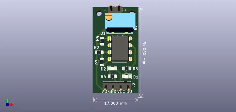
The semi-adjustable potentiometer is included in the resistive divider next to the sensor. Changing the resistance of the potentiometer causes the current to change through the sensor, therefore, the sensor is inserted with a resistor of 150 ohms, to limit the current through it. The advantage is that, using the potentiometer, the analog voltage can also be adjusted at the A0 output. Another difference is the connection of the sensor to the inverter input of the comparator, so to pass D0 in logic state 1, the voltage drop on the sensor must fall below the voltage given by the divider R6-R2 (half the supply voltage). Therefore, this type of module is suitable for sensors whose resistance decreases (for example a thermistor with a negative temperature coefficient, whose resistance is inversely proportional to temperature), even a reed magnetic switch can be used as a sensor. The following modules are built according to the diagram shown: flame sensor (infrared light), touch sensor, sound sensor with small microphone, temperature sensor, sensor with magnetic switch, sensor with large microphone, magnetic field sensor (Hall).

P.S. I'm not the original author of this circuit, I just drew it.

Schematic and Layout
user-img

cris

+ Follow

Topic

View All
LM393 Sensor
  • Comments( 0 )
  • Like( 1 )
/1000
Upload a photo:
You can only upload 1 files in total. Each file cannot exceed 2MB. Supports JPG, JPEG, GIF, PNG, BMP

You May Also Like

View All