Story
Description
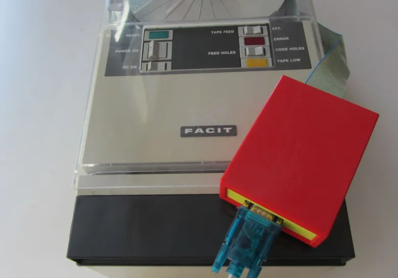
The converter project is intended for the FACIT Type 4070 Code 0001 Paper Tape Punch.
This early 4070 is based on 6V DTL logic and only has a parallel interface.
By interfacing an Arduino Nano to the parallel connector (with proper level conversion) a serial interface is added. The board is powered by the 4070.
The project-board interfaces all signals of the 4070, but only a small subset is used in the first firmware. Data can only transferred at 600 Baud, which is slower than the 4070 punch speed. This means no handshake needs to be implemented
The Arduino console is only used for testing, but can potentially (also) be used for data transfer.
Details
FACIT 4070 to serial interface
A serial interface for DTL-parallel-only versions of the FACIT 4070.
Hardware
The converter board is intended for the FACIT Type 4070 Code 0001 Paper Tape Punch. This version is based on 6V DTL logic and only has a parallel interface.
At the back is a 25 pin sub-DB connector (P1), carrying all signal lines, as wel as ground, +6 V and +24 v power lines. Internally there is also the bridging
board connector (K2). For the current interface, the following A and B side connections are shorted: 1 to 8 (Channels 1 to 8), 9 (sprocket channel), 10 (SD),
11 (PI), 12 (PR) and 20 (ERR2).
There are nine channels, eight being the bits 0 to 7 and the last being the sprocket hole. The layout mapped to the paper tape is:
hole channel (top to bottom)
  O 8
  O 7
  O 6
  O 5
  O 4
  o sprocket (smaller hole)
  O 3
  O 2
  O 1
The input signals of the 4070/0001:
PI - Pulse In
Ch1-8 - Data bits
Ch9 - sprocket hole
SD - Feed direction
All these lines are buffered by ULN2003 and pull-up resistors to the +6V.
The outputs:
PR - Ready
TL - Tape Low
ERR1 - Error
EXT - Ext button
All these lines are attennuated with resistor dividers to adapt the 6V to Arduino save 5V levels.
In the Arduino interface all signals are routed to the Arduino, but the firmware only only uses a subset.
Firmware
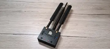
The board is build around an Arduino Nano. The only user interfaces are an RS-232c DE-9 female connector and a flatcable to be connected to the 4070 P1 connector (a DB-25). In the board is a 26 pin header for an one-to-one connection to the P1.
For this implementation, a serial BAUD rate of 600 Bd is selected, as the FACIT 4070 can punch a byte within the transfer time of that byte.
The FACIT can punch 75 characters per second, 600 Bd is equal to 60 characters per second. The advantage is that no serial line handshake is needed.
The USB-connection is currently only used for testing purposes. For this a simple command line interface is available. This is the startup
and help text:
Version 1.1.0
Serial start
Paper Tape Punch v1.1.0 Usage:
B  -    Toggle LED
Cc -    Blink channel (0-8,A,B)
        (8 = SPROCKET, A = SD, B = PI)
H  -    This help text
Pc -    Punch character
Scccc - Send string
A command is terminated with at least a New Line (line feed).
More Code: Serial Interface for a paper tape punch | Hackaday.io
Reposted with permission from the author. And if you want to explore more projects, please follow the author: fjkraan (Hackaday). He has many wonderful projects and is an excellent maker. Enjoy it!