Story
AT commands provide a user-friendly interface for setting up and managing communication modules. LoRaWAN is a low-power, long-range communication protocol commonly used for IoT applications. In this project, we’ll build a device that promotes a deeper understanding of how these communication technologies can work together.
The device, which I’ll call the LoRaWAN Trainer, will help users gain insights into network setup, data transmission, and device management. Once assembled and programmed, it will provide a practical platform for configuring and testing long-range, wireless systems.
We’ll cover both the hardware and software portions of the project in this article. First, though, let’s go over some basic information on AT commands and LoRaWAN.
What Are AT Commands?
AT commands are text-based instructions used to control and configure communication devices. They serve to simplify interactions with the device hardware, allowing developers to focus on system applications instead of low-level programming tasks. The commands are universal across devices and platforms.
Table 1 gives some examples of basic AT commands.
Table 1. Basic AT commands.
| AT Command | Description |
| AT | Tests the connection with the device. |
| AT+GMR | Retrieves firmware version information. |
| AT+RST | Resets the device. |
| AT+CSQ | Checks the signal quality. |
| AT+SEND | Sends data to a specified recipient. |
In IoT applications, AT commands reduce modem management tasks such as network configuration, data transmission, and system diagnostics. They’re also useful for prototyping and debugging IoT systems.
Using AT Commands With LoRaWAN
LoRaWAN, short for Long-Range, Wide-Area Network, is a popular communication protocol for IoT applications. It consumes minimal power, operates on an unlicensed frequency band, and supports both uplink and downlink communications. Figure 1 illustrates some common LoRaWAN applications.

Figure 1. LoRaWAN applications. Image used courtesy of Microchip
AT commands simplify the setup and management of LoRaWAN devices by enabling users to configure, monitor, and operate them effectively through a text-based interface. Table 2 shows some examples of AT commands for use with LoRaWAN.
Table 2. AT commands for LoRaWAN.
| AT Command | Description |
| AT+JOIN | Initiates the network join process. |
| AT+SEND | Transmits uplink data. |
| AT+NJS | Checks the network join status. |
| AT+RSSI | Retrieves the signal strength. |
| AT+BAND | Configures the regional frequency band. |
AT commands allow rapid development and deployment of IoT systems without requiring in-depth knowledge of the underlying communication protocol—in this case, LoRaWAN. Users and developers can use AT commands to set device credentials, join networks, and manage data transmissions.
Want to know more about LoRaWAN? Just need to refresh your memory? Check out “Demystifying LoRa and LoRaWAN Wireless Network Protocols” on the All About Circuits website.
Design of the LoRaWAN Trainer
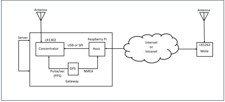
As the article introduction stated, the LoRaWAN Trainer is a hands-on tool designed to help developers and users explore the usefulness of AT commands with LoRaWAN. Figure 2 provides a block diagram of the LoRaWAN Trainer project concept.

Figure 2. LoRaWAN Trainer block diagram. Image used courtesy of Don Wilcher
The trainer has three main hardware components:
- A host computer (the Raspberry Pi).
- A concentrator (the LR1302 gateway module).
- A mote (the LR1262 node module).
It also includes other components that provide supporting features, as we’ll discuss at the end of this section. Before we get to those, however, let’s go over each of the three pieces of hardware listed above.
Host Computer
The Raspberry Pi serves as a central processing unit (CPU) and host computer for the trainer. It runs software to interface with the gateway and node modules.
Concentrator
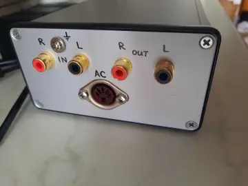
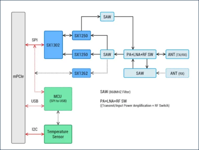
The Elecrow LR1302 gateway module (Figure 3) serves as the communication bridge between the LoRaWAN nodes and the internet. The most important part of this module is the concentrator, which manages message transmissions to and from the LoRaWAN network. A ‘gateway’ is a physical device comprising a concentrator and at least one radio.

Figure 3. The Elecrow LR1302 gateway module. Image used courtesy of Elecrow
Mote
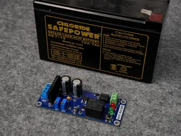
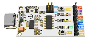
The mote is a LoRaWAN-enabled device used for sending and receiving packet data. In this case, it takes the form of the Elecrow LR1262 node module (Figure 4). This module supports AT commands for configuring network parameters and transmitting messages to the concentrator.

Figure 4. The Elecrow LR1262 node module. Image used courtesy of Elecrow
The mote is essential for establishing uplink and downlink communication for a LoRaWAN system.
Other Components
My version of the trainer also includes a GPS antenna module, though this is optional. The purpose of the antenna module is to allow the transmission and reception of packet data for the trainer by providing global positioning data for the gateway’s location. If you don’t want to use an antenna module, integrating a wireless beacon into the trainer will accomplish the same thing.
The GPS antenna in the trainer provides a one Pulse-Per-Second (PPS) output signal. A serial link to the host computer allows it to send National Marine Electronics Association (NMEA) frames, which contain time and geographical coordinates data.
Some other components of the LoRaWAN Trainer include:
- Raspberry Pi Hat: This PCB connects the gateway module and the Raspberry Pi.
- Keyboard and monitor: Like a power supply, these probably go without saying. Still, make sure you have them handy.
- Assorted cables: You will need a jumper wire and a USB-C cable.
Building the LoRaWAN Trainer
Now that we’ve reviewed the trainer’s components, it’s time to assemble them. The steps are as follows:
- Attach the LR1302 gateway module to the Raspberry Pi Hat.
- Mate the Gateway/Pi Hat Assembly to the Raspberry Pi.
- Attach both antennas to the Raspberry Pi Hat.
- Hook up a keyboard, monitor, and power supply to the Raspberry Pi.
Let’s go over each of these steps.
Attaching the LR1302 Gateway Module to the Raspberry Pi Hat
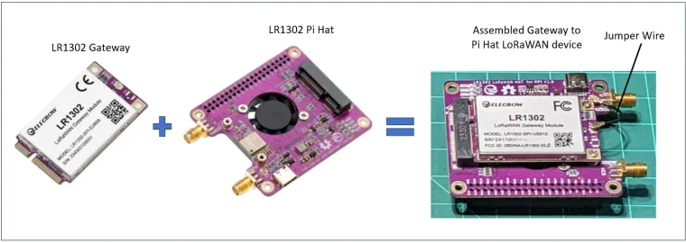
The first step in building the LoRaWAN Trainer is attaching the LR1302 gateway module to the Raspberry Pi Hat (Figure 5). The Pi Hat will serve as a bridge between the gateway module and the host computer.

Figure 5. Step 1: assemble the gateway module and the Pi Hat into a single device. Image used courtesy of Don Wilcher
The Pi Hat includes a mini–PCIe (mPCIe) connector. To connect the gateway module and the Raspberry Pi Hat, insert the module into the mPCIe connector and attach the jumper wire to the PCB. When inserting the LR1302 module into the Pi hat PCB, make sure that the gateway edge connector is properly aligned to the PCB mPCIe connector.
Mating the Gateway/Pi Hat Assembly to the Raspberry Pi
Next, we need to align the Raspberry Pi 40-pin male connector with the Pi Hat 40-pin female connector. This step is shown in Figure 6.

Figure 6. Step 2: attach the Raspberry Pi Hat to the Raspberry Pi. Image used courtesy of Don Wilcher
Then, connect the Pi Hat to the Raspberry Pi’s USB port using a USB-C cable.
Attaching the Antennas to the Raspberry Pi Hat
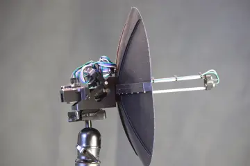
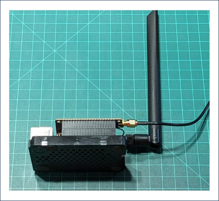
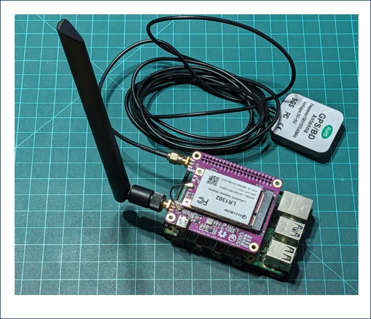
Attach the large antenna and the GPS antenna to the Pi Hat as shown in Figure 7.

Figure 7. Step 3: attach both the large antenna and GPS antenna to the Raspberry Pi Hat. Image used courtesy of Don Wilcher
Final Hardware Assembly
As of Step 3, all of the LoRaWAN trainer’s primary components have been assembled. All that’s left is to attach the keyboard and monitor to the Raspberry Pi’s available USB ports, plug in the power supply, and turn the Raspberry Pi on. If everything is working properly, the following LEDs should be lit up:
- The green power light.
- The red configuration light.
- The blue receive (RX) light.
- The green transmit (TX) light.
The cooling fan on the bottom of the Pi Hat PCB should be running as well. This completes the hardware build of the LoRaWAN Trainer.
Software Installation and Use Cases
For the software portion of this project, we’ll draw on Elecrow’s wiki. Instructions for installing the packet software and configuring the Raspberry Pi can be found on the LR1302 gateway module’s wiki page. The AT commands needed for the node module to communicate with the gateway module also have their own wiki page.
Once the software installation is complete, you might also consider exploring the use cases Elecrow provides for the node module. Using the Tera-Term software terminal package, the wiki page examples can be executed and demonstrated quite easily on your LoRaWAN Trainer. An example transmit/receive session using Tera-Term is shown in Figure 8.

Figure 8. A LoRaWAN Trainer Tera-Term session. Image used courtesy of Don Wilcher
Wrapping Up
Congratulations—you now have a complete LoRaWAN Trainer! As IoT continues to evolve, such training tools will allow the exploration of innovative long-range communication devices and systems.