Currency
Toggle Nav


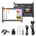
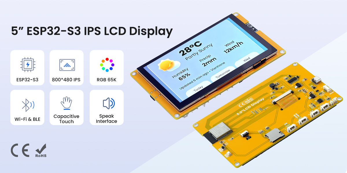
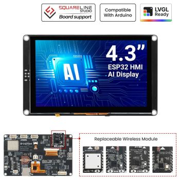
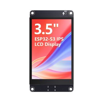
5” ESP32-S3 IPS Display| 800×480 Capacitive Touchscreen | Supports WiFi/Bluetooth | With Speaker Interface
$29.90
Availability:
In stock
SKU
DLE06050B
Weight
250g
Related Products:


[ESP32-S3 Main Controller] Dual-core 240MHz, 8MB PSRAM + 16MB Flash, powerful performance
[5-inch IPS Full-View Screen] 800×480 resolution, 450cd/m² high brightness
[Capacitive Touch] GT911 driver, I2C communication, responsive and smooth interaction
[Wireless Connectivity] 2.4GHz WiFi + Bluetooth 5.0, easy access to the IoT
[Audio Expansion] Built-in speaker interface, supports voice playback and prompts
[Rich Interfaces] Type-C download, TF card, UART, SPI, expanded I/O interfaces.
[Reliable Quality] Multiple aging tests, stable operation in a wide temperature range of -30~80℃
[Out-of-the-Box Use] Sample programs + driver support, quick start to development
[❤️What you get] 24H Friendly Customer Service and 1 Year warranty.1x 5.0" ESP32 display,1x Charging Cable,1x 4 Pin Cable.
Frequently Bought Together

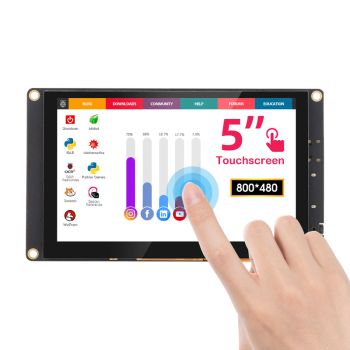
5" ESP32-S3 HMI Display
This 5-inch IPS full-view display module features an 800x480 resolution and a sensitive capacitive touchscreen, powered by an ESP32-S3 main controller. The controller utilizes an Xtensa LX7 dual-core processor with a clock speed of up to 240MHz, 8MB of PSRAM, and 16MB of Flash memory. It supports 2.4GHz Wi-Fi and Bluetooth 5.0 wireless communication, providing ample computing power for IoT and embedded HMI applications.
The module integrates a Type-C interface (supporting one-click download), a Micro TF card slot, a UART serial port, an SPI expansion interface, and a speaker interface, facilitating connection to various peripherals and sensors. The IPS screen supports RGB565 65K colors, boasts a brightness of up to 450 cd/m², and operates within a temperature range of -30~80℃, ensuring stable operation in various environments. It provides abundant sample programs and underlying driver technology support. Whether you're building a smart home control panel, an industrial HMI terminal, or a voice‑enabled IoT device, this 5" ESP32-S3 display delivers the performance and flexibility you need.
Quick Click to where you are interested: #Feature, #Interface definition, #Specification, #Documents, #Review.
OEM customized requests can be discussed(based on MOQ), you can contact us at service@elecrow.com.


Feature
- ESP32-S3 Main Controller: Dual-core Xtensa LX7 processor, 240MHz clock speed, built-in 8MB PSRAM + 16MB Flash, supports 2.4GHz WiFi and Bluetooth 5.0.
- 5-inch IPS Full-View Color Screen: 800x480 resolution, RGB565 65K color display, 450cd/m² high brightness, vibrant colors, and wide viewing angles.
- Sensitive Capacitive Touch: Uses GT911 driver IC, I2C communication interface, fast response, supports smooth human-machine interaction.
- Audio Playback Support: Built-in 1.25mm 2P speaker interface, allowing external speakers to play audio, suitable for voice prompts and multimedia projects.
- Abundant Expansion Interfaces: Onboard Type-C (power supply/one-click download), TF card slot, UART0/1, SPI peripheral interface and multiple expansion I/O pins.
- Convenient development experience: Standard Type-C interface with integrated one-click download circuit; provides sample programs and underlying driver technology support
- Reliable quality: The module has undergone aging tests and multiple inspections, supports wide temperature range of -30~80℃, and is suitable for long-term stable operation.
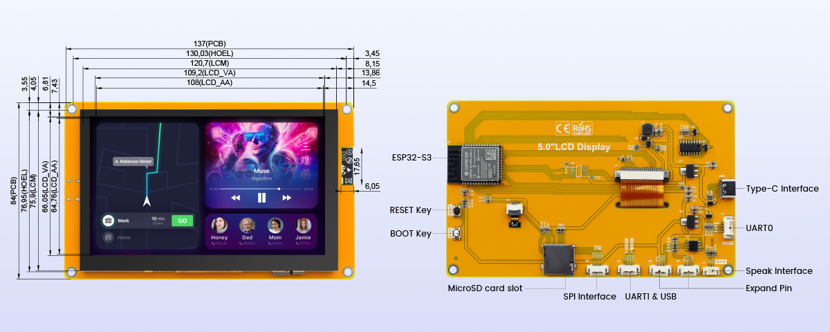
Interface Definition
|
Interface Name |
Function Description |
|
ESP32-S3 |
Display module main control,control board peripheral and external peripheral. |
|
MicroSD card slot |
A MicroSD card is inserted to expand the storage space for storing large data such as characters, pictures, and audio files. |
|
UART0 |
1.25mm 4P connector.It can be used for serial debugging, downloading, and communication. An external USB to serial port module is required. |
|
BOOT Key |
|
|
Type-C Interface |
|
|
RESET Key |
Used for ESP32 master control and LCD reset, level reset after pressing. |
|
Expand Pin |
1.25mm 4P socket, leading out GPIO17/GPIO18 pins. |
|
UART1 & USB |
1.25mm 4P socket, leading out four free pins: GPIO17, GPIO18, GPIO19 and GPIO20. GPIO17 and GPIO18 can be used for UART1, while GPIO19 and GPIO20 are compatible with the USB protocol. |
|
SPI Interface |
1.25mm 4P socket, designed for connecting external SPI communication devices. This SPI interface is shared with the resistive touch screen and SD card, and can also be used as GPIO. |
|
Speaker connector |
1.25mm 2P connector for connecting speakers to play audio. |
Specification
|
ESP32 Module |
|
|
Chip |
ESP32-S3 (N16R8) |
|
CPU |
Xtensa LX7 32-bit dual-core processor |
|
Frequency |
240MHz(Max) |
|
Memory |
384KB ROM+512KB SRAM+16KB RTC SRAM+8M internal OPI PSRAM+16M external SPI Flash |
|
Wi-Fi |
2.4GHz, 802.11b/g/n mode |
|
Bluetooth |
Bluetooth V5.0 BR/EDR and Bluetooth LE standard |
|
Screen |
|
|
Panel Size |
5.0 inch |
|
Panel Type |
IPS |
|
Touch Screen Type |
Capacitive touch screen |
|
Resolution |
800x480 |
|
Active Area |
108(W)x64.8(H)(mm) |
|
Number of Pixels |
65K(RGB565) |
|
Display Driver IC |
ST7282 |
|
Screen interface |
RGB565-16Bit |
|
View Angle |
ALL ’CLOCK |
|
Brightness(TYP) |
450 cd/m2 |
|
Backlight Type |
White LED |
|
Touch Driver IC |
GT911 |
|
Communication Interface |
IIC |
|
Pixel Size |
0.153(H)x0.153(mm) |
|
Other |
|
|
Working Voltage |
5.0V |
|
Total current (typical value) |
290mA |
|
Total power consumption (typical value) |
1.45W |
|
Power interface |
Type-C |
|
Operating temperature |
-30~80(℃) |
|
Storage temperature |
-30~80(℃) |
|
Module Size |
137(W)x84(H)x13.75(D) |
|
Net Weight |
120g |
ESP32 Pin Assignment
|
Onboard Equipment |
ESP32 Connect Pins |
Pin Description of Onboard Equipment |
|
LCD |
IO40 |
LCD panel chip select control signal, active low |
|
IO46 |
Data enable control pin |
|
|
IO41 |
Vertical sync signal control pin |
|
|
IO39 |
Horizontal sync signal control pin |
|
|
IO42 |
Pixel clock control pin |
|
|
IO42/48/47/21/14 |
5-bit RED data pin |
|
|
IO5/6/7/15/16/4 |
6-bit GREEN data pin |
|
|
IO8/3/46/9/1 |
5-bit BLUE data pin |
|
|
Capacitive Touch Screen |
IO20 |
Capacitive touchscreen IIC bus clock control pin |
|
IO19 |
Capacitive touchscreen IIC bus data write control pin |
|
|
IO38 |
Capacitive touchscreen reset control pin |
|
|
IO18 |
Capacitive touchscreen interrupt control pin |
|
|
MicroSD Card |
IO10 |
SD card SPI bus chip select control pin |
|
IO11 |
SD card SPI bus data read control pin |
|
|
IO13 |
SD card SPI bus data write control pin |
|
|
IO12 |
SD card SPI bus clock control pin |
|
|
Button |
IO0 |
Download mode selection button (press and hold this button while powering on, then release to enter download mode) |
|
EN |
ESP32-S3 reset button, low-level reset (shared with LCD screen reset) |
|
|
Serial Port |
RXD0(IO43) |
ESP32-S3 serial port receive signals (can be used as general I/O if the serial port is not used) |
|
TXD0(IO44) |
ESP32-S3 serial port transmit signals (can be used as general I/O if the serial port is not used) |
|
|
SPI Interface |
IO19 |
SPI bus chip select control pin: When USB signal function is not used, it can be used as a general-purpose I/O port. |
|
IO11 |
SPI bus data read control pin: When SD card function is not used, it can be used as a general-purpose I/O port. |
|
|
IO13 |
SPI bus data write control pin: When SD card function is not used, it can be used as a general-purpose I/O port. |
|
|
IO12 |
SPI bus clock control pin: When SD card function is not used, it can be used as a general-purpose I/O port. |
|
|
Extension Interface |
IO18 |
When touch, audio, and SD card functions are not used, it can be used as a general-purpose I/O port. |
|
IO17 |
When audio and SD card functions are not used, it can be used as a general-purpose I/O port. |
|
|
USB |
IO19 |
USB bus differential signal data line negative terminal |
|
IO20 |
USB bus differential signal data line positive terminal |
|
|
UART1 |
IO17 |
ESP32-S3 serial port 1 transmit signal pin |
|
IO18 |
ESP32-S3 serial port 1 receive signal pin |
|
|
Speak audio playback interface |
IO18 |
I2S left and right channel clock pins |
|
IO17 |
I2S audio data transmission pins |
|
|
IO0 |
I2S bit clock pins |
Package List
- 1x 5 inch ESP32 LCD Module
- 1x Type-C Cable
- 1x 4Pin Cable
Wiki & External links
What do they say?
| New 5-inch touchscreen doubles as an affordable smart home hub with wide feature set | |
| Magazine: NOTEBOOKCHECK |
Write Your Own Review
Bestselling Products You May Like

New Products You May Want


Warranty
Service
VIP Distributor
Discount
Professional
Tech Support
Fast
Delivery
×
 Add to cart successfully!


Customers Who View This Item Also Bought