Currency
Toggle Nav

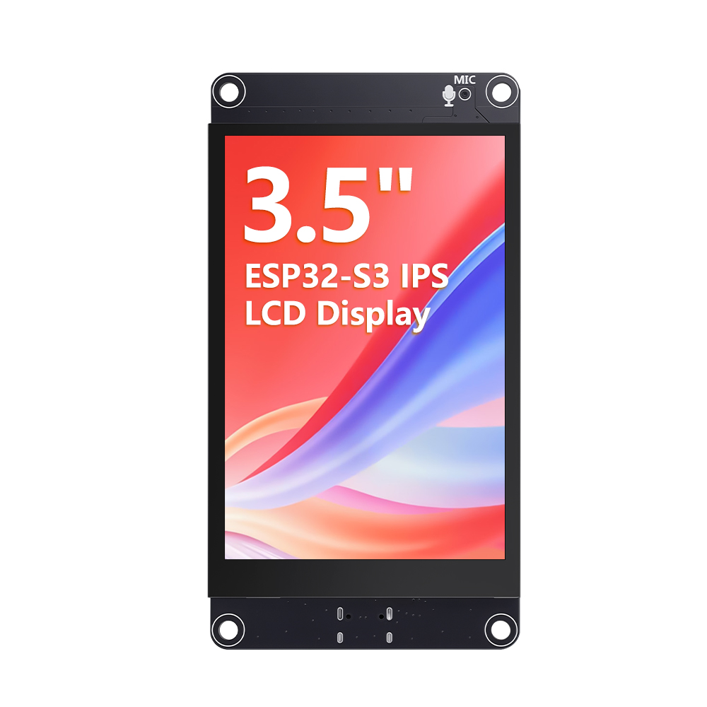


3.5” ESP32-S3 Display with 320x480 Capacitive IPS Touch Panel | Speaker/Mic/BAT Interface | Supports AI Voice Chat
$20.90
Availability:
In stock
SKU
DLE06235B
Weight
150g
Related Products:

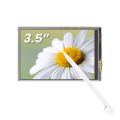
[ESP32-S3 Main Controller] Dual-core 240MHz, 8MB PSRAM + 16MB Flash, powerful computing performance
[3.5-inch IPS Full-View Screen] 320×480 resolution, fully laminated capacitive touch, clear display, and sensitive touch
[Voice Interaction] High-sensitivity microphone + speaker interface, supports Xiaozhi AI voice chat
[Lithium Battery Management] Built-in charging circuit, supports 3.7V batteries, easily creating portable devices
[Rich Interfaces] Type-C one-click download, TF card, IIC, UART, SPI, flexible expansion
[Reliable Quality] Multiple aging tests, stable operation in a wide temperature range of -30~80℃
[❤️What you get] 24H Friendly Customer Service and 1 Year warranty.1x 3.5" display,1x Speaker, 1x Charging Cable,1x 4pin Cable.
Frequently Bought Together


3.5" ESP32-S3 IPS Touch Display
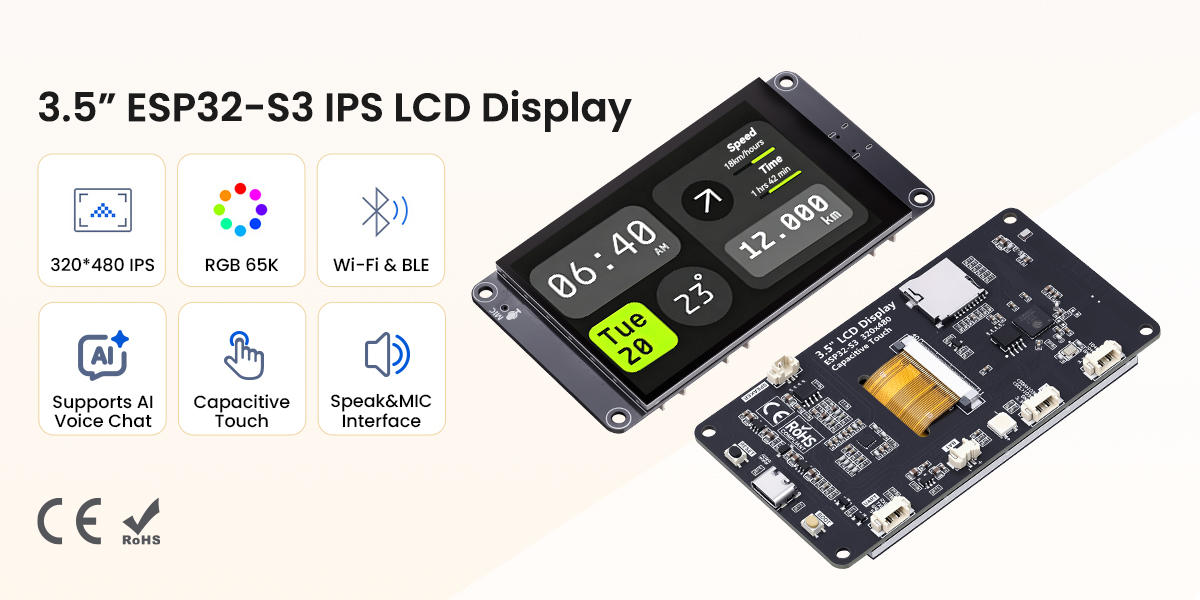
This 3.5-inch ESP32-S3 development board integrates display, touch, voice, and wireless communication, specifically designed for intelligent interaction and IoT applications. It utilizes a dual-core ESP32-S3 processor with a clock speed of up to 240 MHz, 8 MB of PSRAM, and 16 MB of Flash memory. It supports 2.4GHz Wi-Fi and Bluetooth 5.0, providing ample computing power for complex human-machine interfaces and AI algorithms.
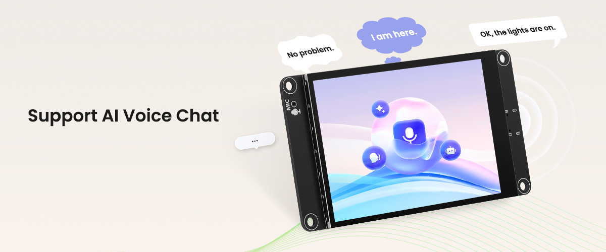
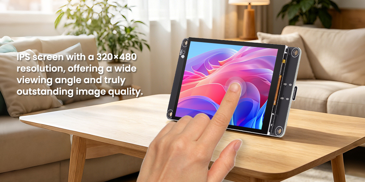
The screen is a 3.5-inch IPS full-view color display with a resolution of 320×480 and 65K colors, offering vibrant colors and a wide viewing angle. The capacitive touchscreen ensures high sensitivity and a smooth human-machine interaction experience. An onboard high-sensitivity microphone and speaker interface (with a speaker included) enable voice capture and playback, supporting the "Xiao Zhi AI" voice chat function, simplifying voice interaction development.
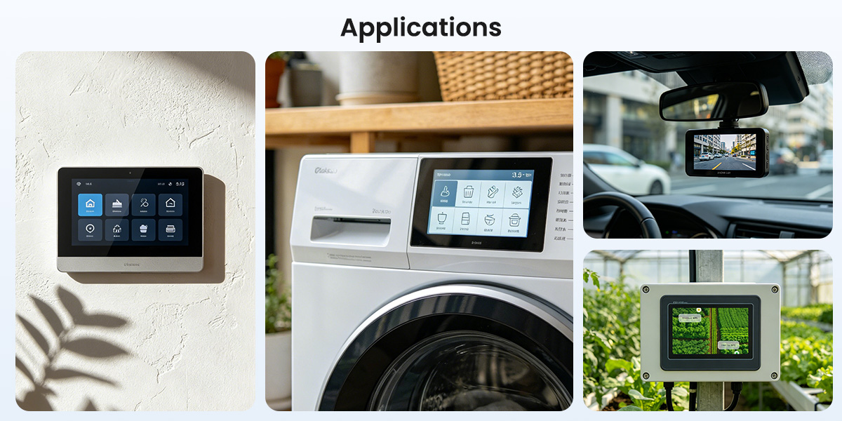
The module integrates a Type-C interface (supporting one-click download), a TF card slot, and a lithium battery charging management circuit (supporting external 3.7V lithium batteries), facilitating the development of portable devices. It offers multiple expansion interfaces such as SPI, IIC, and UART, facilitating connection to various sensors and peripherals. The product has undergone aging tests and multiple inspections, supports a wide operating temperature range of -30~80℃, and, with abundant sample programs and underlying driver technology support, is an ideal choice for smart home control systems, AI voice assistants, and portable smart terminals.
Quick Click to where you are interested: #Feature, # Interface Definition, #Specification, #Documents, #Review.
OEM customized requests can be discussed(based on MOQ), you can contact us at service@elecrow.com.

Hardware Overview
Feature
- High-performance ESP32-S3 main controller: Dual-core Xtensa LX7 processor, 240MHz clock speed, built-in 8MB PSRAM + 16MB Flash, supports 2.4GHz WiFi and Bluetooth 5.0.
- 3.5-inch IPS full-view color screen: 320×480 resolution, 65K colors, capacitive touch, clear display, sensitive touch, and smooth response.
- Voice interaction support: Onboard high-sensitivity microphone interface and an external speaker (included), supporting voice chat for easy development of voice control and audio playback applications.
- Lithium battery charge/discharge management: Built-in battery charging management circuitry, supports external 3.7V lithium batteries for safe charging and discharging.
- Rich expansion interfaces: Onboard Type-C (one-click download), TF card slot, IIC, UART, SPI, and other interfaces for easy connection to various sensors and peripherals.
- Convenient Development Experience: Standard Type-C interface integrates a one-click download circuit, eliminating the need for manual button presses; provides complete sample programs and underlying driver technology support.
- Status Indicators: Built-in RGB three-color indicator lights allow for customizable display of device status, facilitating debugging and interactive feedback.
- Reliable Quality: The module undergoes aging tests and multiple inspections, supports a wide operating temperature range of -30~80℃, and is suitable for various indoor and outdoor environments.
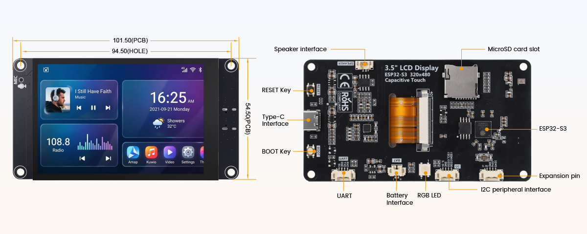
Interface Definition
|
Interface Name |
Function Description |
|
ESP32-S3 |
Main control of the display module, working together with the peripheral circuit, is used to control on-board peripherals and external peripherals. |
|
MicroSD card slot |
Insert a SD card to expand storage space, such as storing large data content such as font libraries, images, audio files, etc. |
|
RGB tricolor light |
Contains LEDs of three colors: red, green, blue. It has a built-in control IC and only needs one IO port to control. It can be used for LED testing and status indication. |
|
UART |
1.25mm4P socket. It can be used for serial port debugging, downloading, and communication. An external USB to serial port module is required. |
|
Battery interface |
1.25mm 2P socket. Used to connect to a 3.7V polymer lithium battery, charge the battery through the battery management circuit, and can also be used for battery power supply. Note the positive and negative terminals of the interface. |
|
BOOT key |
Used to enter the download mode or key test. Press and this key to power up, then release to enter the download mode, or after powering up, press and hold this key, then press the RESET key, release the RES key and then release this key, you can also enter the download mode. When you don't need to enter the download mode, this key can be used as a normal key |
|
TYPE-C interface |
It is used for module power supply and program download, debugging. This interface is connected to the internal USB bus of ESP32-S3, which can generate a USB serial port. Note: win10 and above systems support USB virtual serial port function. If you use this interface on other versions of the system, you need to solve the problem USB virtual serial port not working by yourself. |
|
RESET key |
For ESP32-S3 main control and LCD reset, press to reset low level. |
|
Expansion pin |
1.25mm 4P socket. Two pins are GPIO45 and GPIO46. It can be used to connect other peripherals. |
|
Speaker interface |
1.25mm P socket. Used to connect the speaker to play audio. Used to connect the speaker to play audio (maximum support 1.5W (8Ω) or 2W4Ω) speaker. |
|
I2C peripheral interface |
1.25mm 4P connector. Used for connecting external IIC communication devices. This IIC interface is shared with capacitive touchscreens. Can also be used for general I/O. |
Specification
|
ESP32 Module |
|
|
Chip |
ESP32-S3 (N16R8) |
|
CPU |
Xtensa LX7 32-bit dual-core processor |
|
Frequency |
240MHz(Max) |
|
Memory |
384KB ROM+512KB SRAM+16KB RTC SRAM+8M internal OPI PSRAM+16M external SPI Flash |
|
Wi-Fi |
2.4GHz, 802.11b/g/n mode |
|
Bluetooth |
Bluetooth V5.0 BR/EDR and Bluetooth LE standard |
|
Screen |
|
|
Panel Size |
3.5 inch |
|
Panel Type |
IPS |
|
Touch Screen Type |
Capacitive touch screen |
|
Resolution |
320x480 |
|
Active Area |
48.96x73.44(H)(mm) |
|
Number of Pixels |
65K(RGB565) |
|
Display Driver IC |
ST77922 |
|
Display interface |
QSPI(Received on ESP32-S3) |
|
View Angle |
ALL ’CLOCK |
|
Brightness(TYP) |
300 cd/m2 |
|
Backlight Type |
White LED*6 |
|
Communication Interface |
IIC |
|
Pixel Size |
0.153(H)x0.153(mm) |
|
Other |
|
|
Working Voltage |
5.0V |
|
Backlight current |
120mA |
|
Charging current |
Maximum value: 500mA Module actual: 290mA |
|
Power |
0.96(Only the display works) 1.76(Display, speaker, battery charging all work) |
|
Total power consumption (typical value) |
1.45W |
|
Charging saturation voltage |
4.24V |
|
Charging temperature |
Module actual maximum value: 62℃ |
|
Charging battery |
3.7V lithium polymer battery (not included) |
|
Power interface |
USB(Type-C) |
|
Operating temperature |
-30~80(℃) |
|
Storage temperature |
-30~80(℃) |
|
Module Size |
54.50(W)x101.50(H)x10.00(D)(mm) |
|
Net Weight |
50g |
ESP32 Pin Assignment
|
Onboard Equipment |
ESP32 Connect Pins |
Pin Description of Onboard Equipment |
|
LCD |
IO10 |
LCD screen chip select control signal, low level active |
|
IO12 |
LCD QSPI bus clock signal |
|
|
IO11 |
LCD QSPI data bus D0 |
|
|
IO13 |
LCD QSPI data bus D1 |
|
|
IO14 |
LCD QSPI data bus D2 |
|
|
IO9 |
LCD QSPI data bus D3 |
|
|
EN |
LCD screen reset control signal, low level reset (share reset pin with ESP32-S3 main control) |
|
|
IO41 |
LCD screen backlight control signal ( level turn on backlight, low level turn off backlight) |
|
|
Capacitive Touch Screen |
IO38 |
Capacitive touch screen I2C bus data signal (share with audio codec IC and extended I2C) |
|
IO39 |
Capacitive touch screen I2C bus clock signal (share with audio codec IC and extended I2C) |
|
|
IO48 |
Capacitive touch screen reset control signal, low level |
|
|
IO47 |
Capacitive touch screen interrupts the input signal, input low level when touch event occurs. |
|
|
RGB light |
IO40 |
RGB three-color LED light control signal with built-in control IC. Different timing can be input to control the internal red, green and blue three kinds of beads respectively. |
|
MicroSD Card |
IO5 |
SD card SDIO bus clock signal |
|
IO4 |
SD card SDIO bus command signal |
|
|
IO6/7/2/3 |
SD SDIO bus data signal DATA0~DATA3 |
|
|
Audio |
IO1 |
Audio power amplifier IC enable pin, low level enable |
|
IO17 |
Audio I2S bus master clock signal |
|
|
IO18 |
Audio I2S bus bit clock signal |
|
|
IO16 |
Audio I2S bus bit output data signal |
|
|
IO21 |
Audio I2S bus left and right channel selection signal. High level: right channel; low level: left channel |
|
|
IO15 |
I2S bus bit input data signal |
|
|
IO38 |
Audio codec IC's I2C bus data signal (share with capacitive touch screen and extended I2C) |
|
|
IO39 |
Audio codec's I2C bus clock signal (share with capacitive touch screen and extended I2C) |
|
|
Button |
IO0 |
Download mode selection button (hold this button to power up, then release enter download mode) |
|
EN |
ESP32-S3 reset button, low level reset (share with LCD screen reset) |
|
|
Serial Port |
RXD0(IO43) |
ESP32-S3 serial port 0 receive signal interface (if the serial port communication function is not used, it can be used as a IO port) |
|
TXD0(IO44) |
ESP32-S3 serial port 0 receive signal interface (if the serial port communication function is not used, it can be used as a general port) |
|
|
Battery |
IO8 |
Battery voltage ADC value acquisition input signal |
|
Expansion pin |
IO45 |
ports that can be used to connect peripherals |
|
IO46 |
ports that can be used to connect peripherals |
|
|
GND |
GND |
|
|
VCC |
3.3V |
|
|
I2C peripheral interface |
IO38 |
Expansion interface I2C bus data signal (shared with capacitive touch screen and audio codec IC, can be used a general IO when touch and audio functions are not used, otherwise it can only be used as an I2C interface) |
|
IO39 |
Expansion interface I2C bus clock signal ( with capacitive touch screen and audio codec IC, can be used as a general IO when touch and audio functions are not used, otherwise it can only be used as an I2C interface) |
Package List
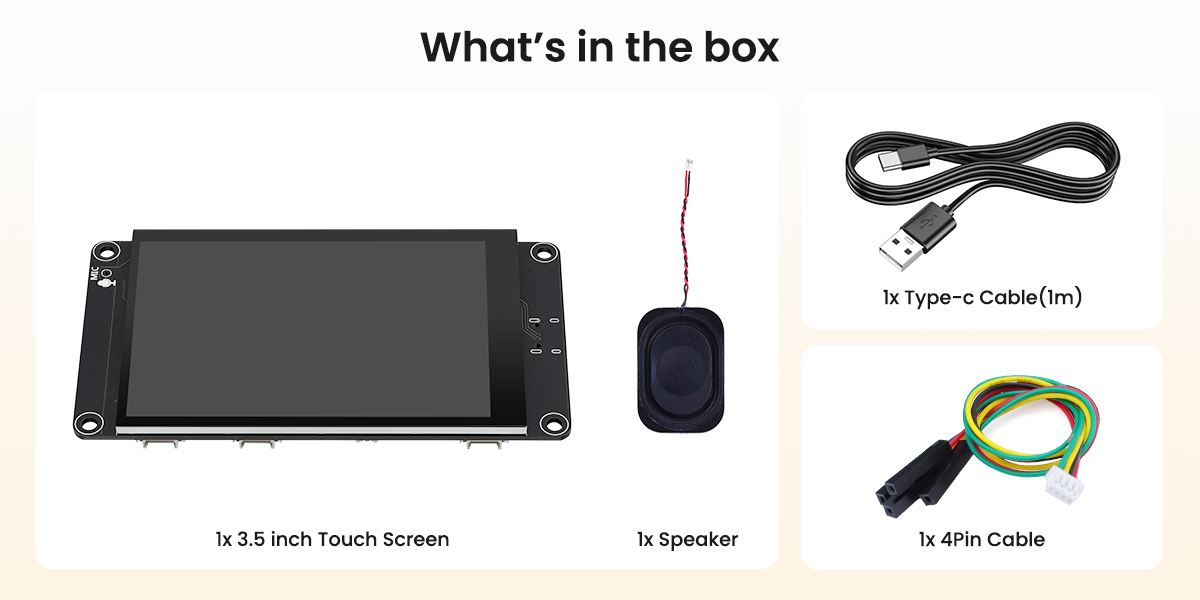
- 1x 3.5 inch ESP32 LCD Module
- 1x Type-C Cable
- 1x 4Pin Cable
- 1x Speaker
Wiki & External links
What do they say?
| 3.5-inch display with microphone: This cheap screen can be a smart home hub | |
| Magazine: NOTEBOOKCHECK |
Write Your Own Review
Bestselling Products You May Like



New Products You May Want

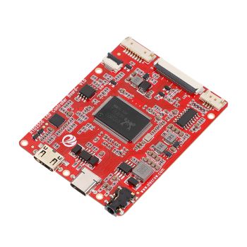
RTD2556 Driver Board/Controller Board for HD Monitor With EDP 30Pin 1920x1080p Touch Function
was
$20.90
Special Price
$14.63

Warranty
Service

VIP Distributor
Discount

Professional
Tech Support

Fast
Delivery
×
 Add to cart successfully!


Add to cart successfully!
Customers Who View This Item Also Bought