

Story
Detailed Project Description — Smart Star-Delta Electrical Control Panel
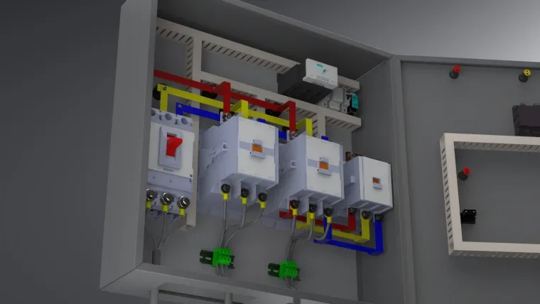
This project presents a Smart Star-Delta Electrical Control Panel designed to safely and efficiently start three-phase induction motors while minimizing inrush current. The panel implements a star–delta transition sequence controlled by a timer relay, with full overload protection, pushbutton control, and visual indicators. It is intended for industrial environments, training labs, and small automation setups where robust motor control and clear wiring documentation are essential.
⚙️ Overview and Purpose
When large motors start directly on line, they draw a high inrush current (6–8 times the full-load current), causing mechanical stress and voltage dips. The Star-Delta starter temporarily connects the motor windings in a star configuration to reduce current, then switches to delta after a preset delay. This project demonstrates a clean, reproducible wiring solution using three contactors, a timer relay, and an overload relay arranged in a compact metal enclosure. The design also includes emergency stop, indicator lamps, terminal labels, and a clear maintenance layout.
System Components
The panel uses:
-
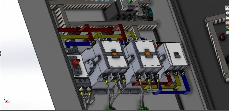
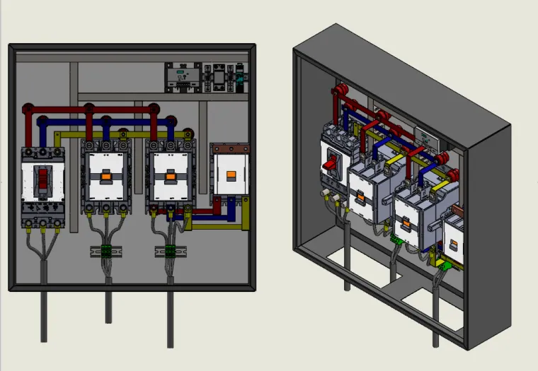
Main Contactor, Star Contactor, and Delta Contactor (Schneider LC1D series)
-
Thermal Overload Relay for protection against overcurrent
-
Omron H3CR-A8 Timer Relay for transition timing
-
Control Transformer to step down 415 V AC to 24 V AC control voltage
-
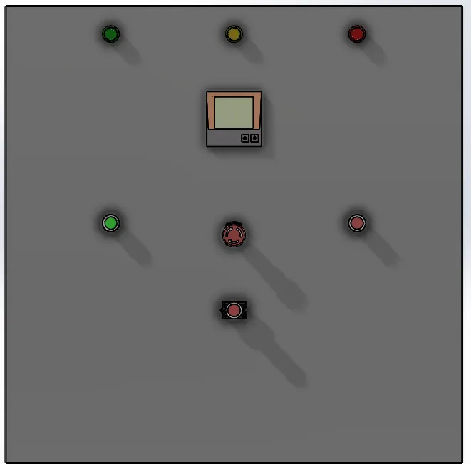
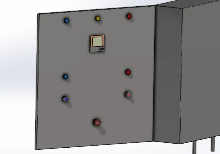
Start, Stop, and Emergency Pushbuttons
-
Indicator Lamps (R/Y/B) for status display
-
Rittal enclosure with DIN rails, terminal blocks, wiring ducts, and cable glands
All parts are listed in the Bill of Materials section with store links and manufacturer information.
⚡ How It Works
When the Start pushbutton is pressed, the Main and Star contactors energize simultaneously, connecting the motor windings in a star configuration. The timer relay starts counting. After the preset time (typically 5 seconds), the timer de-energizes the Star contactor and energizes the Delta contactor through its delayed contacts, connecting the motor windings in delta. The motor then runs under full-load torque.
The Stop pushbutton or overload relay trip immediately drops all contactors. The Emergency Stop button provides a manual hard cutoff. Indicator lamps show operating state: green for run, yellow for transition, and red for fault/trip.
Design Features
-
Adjustable Transition Time — via the Omron timer (0.5–30 s range).
-
Mechanical and Electrical Interlocks — between Star and Delta contactors to prevent overlap.
-
Comprehensive Protection — overload, short-circuit (through fuses/MCCB), and emergency stop.
-
Low-voltage Control Circuit — isolated via control transformer for operator safety.
-
Professional Layout — components arranged logically, labeled, and routed using cable ducts.
-
Documentation — full schematic and wiring layout provided for easy reproduction.
Step-by-Step Build Summary
-
Mechanical Assembly: Mount the enclosure, DIN rails, and all components. Drill cable-gland holes as per layout.
-
Control Wiring: Connect pushbuttons, timer, and contactor coils according to the provided schematic. Ensure auxiliary contacts are correctly wired for interlocking.
-
Power Wiring: Connect incoming supply through MCCB/fuses to the Main contactor, then to the motor terminals via the Star and Delta contactors.
-
Grounding: Bond all metal parts to earth and verify continuity.
-
Testing: Perform no-load test to confirm sequence (Main + Star → Main + Delta). Adjust timer if needed.
-
Commissioning: Connect the motor, energize, and observe current draw and transition timing.
Documentation & Attachments
Included files (recommended for upload):
-
StarDelta_Schematic.pdf — control circuit and power diagram.
-
Panel_Layout.pdf — component placement and terminal numbering.
-
BOM_StarDelta.xlsx — complete parts list.
-
SolidWorks_Enclosure.SLDASM — 3D model for panel assembly.
-
Test_Checklist.pdf — commissioning procedure.
-
Wiring_Photos.zip — real build images.
Tools & Software Used
-
AutoCAD Electrical — circuit design and documentation
-
SolidWorks 2025 — enclosure and layout modeling
-
Fluke Multimeter — continuity and voltage testing
-
Knipex crimping tools — terminal preparation and cable finishing
Troubleshooting Tips
-
Ensure Star and Delta coils are not powered together — check auxiliary NC contacts.
-
Verify coil voltage matches control voltage.
-
Adjust timer for smooth transition (start at 5 s).
-
Tighten all terminals to torque spec to prevent overheating.
-
Test overload relay trip manually before live operation.
Project Significance
This project bridges classical electrical control design and modern documentation quality. It’s a complete, teachable model of industrial motor starting principles — valuable for students, automation trainees, and engineers building motor control panels. By following the documentation, others can replicate the design, avoid wiring errors, and confidently build safe, professional-grade Star-Delta panels.