user-img

Vladimir Todorov

  • 1 Projects
  • 1 Followers
  • Nov 21,2025
+ Follow

A simple but very useful Zener diode tester

A simple but very useful Zener diode tester

A simple but very useful Zener diode tester
 
  • thumbnail-img
 

Story

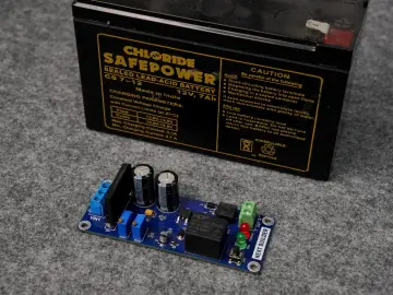
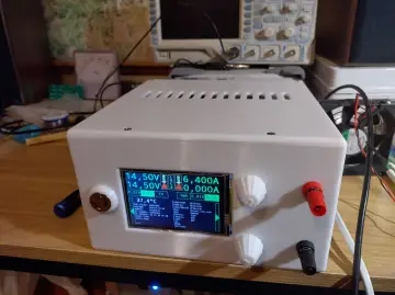
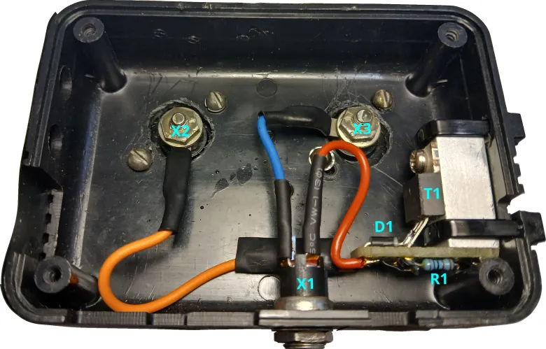
Lately, I've been heavily involved in reverse engineering. Sometimes I need to check at what voltage a Zener diode breaks down. For this purpose, I built a tester. It consists of a constant current source, a general-purpose power supply, and a voltmeter. The constant current sources is simple - one Depletion MOSFET and a resistor.

Electronic scheme of the tester

The Idz current is adjusted with resistor R1. 

Infineon provides a very comprehensive Application Note on the operation of Depletion MOSFETs as constant current sources. Since it's an old article that is difficult to find, I have included it .

Application Note title: Depletion MOSFETs.

Author: Pradeep Kumar Tamma. 

Document reference: AN_201410_PL11_003.

Revision 1.0, 2015-02-03. 

Here is the relationship between

                                                      R1 ,

                                                     Id        :  the desired current ,

                                                    Vgs(th) :  the gate threshold voltage of the MOSFET and 

                                                     Idss      :  the on-state current at VGS = 0 V .


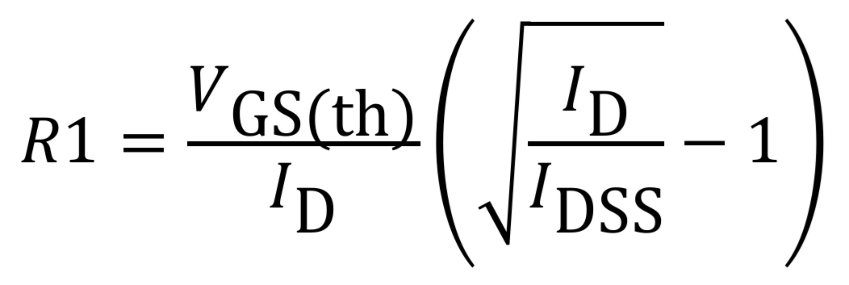
According to the DN2540N5-G datasheet, VGS(th) ranges from 1.5 V to 3.5 V. Тhe minimum Idss value is 0.15 A, and the maximum value is not specified.

The table below shows the calculated values of R1 for specific values of VGS(th), with Idss and Id held constant.

                VGS(th) , V                 Idss,A                 Id,A                R1, Ω
                     1.5                      0.15                      0.001                      1378
                     2.0                      0.15                      0.001                      1837
                     2.5                      0.15                      0.001                      2296
                     3.0                      0.15                      0.001                      2755
                     3.5                      0.15                      0.001                      3214

I have included ODS and XLSX files which contain the implemented formula. You can view the results and perform calculations with different values there.

Practice, however, has shown that instead of calculating the resistor, the easiest way is to place a potentiometer in place of R1 and use it to adjust the current. That's what I did. Afterwards, I replaced the potentiometer with a fixed resistor of an appropriate value. The calculations gave me a guideline for the potentiometer's value.

Below are some photos :


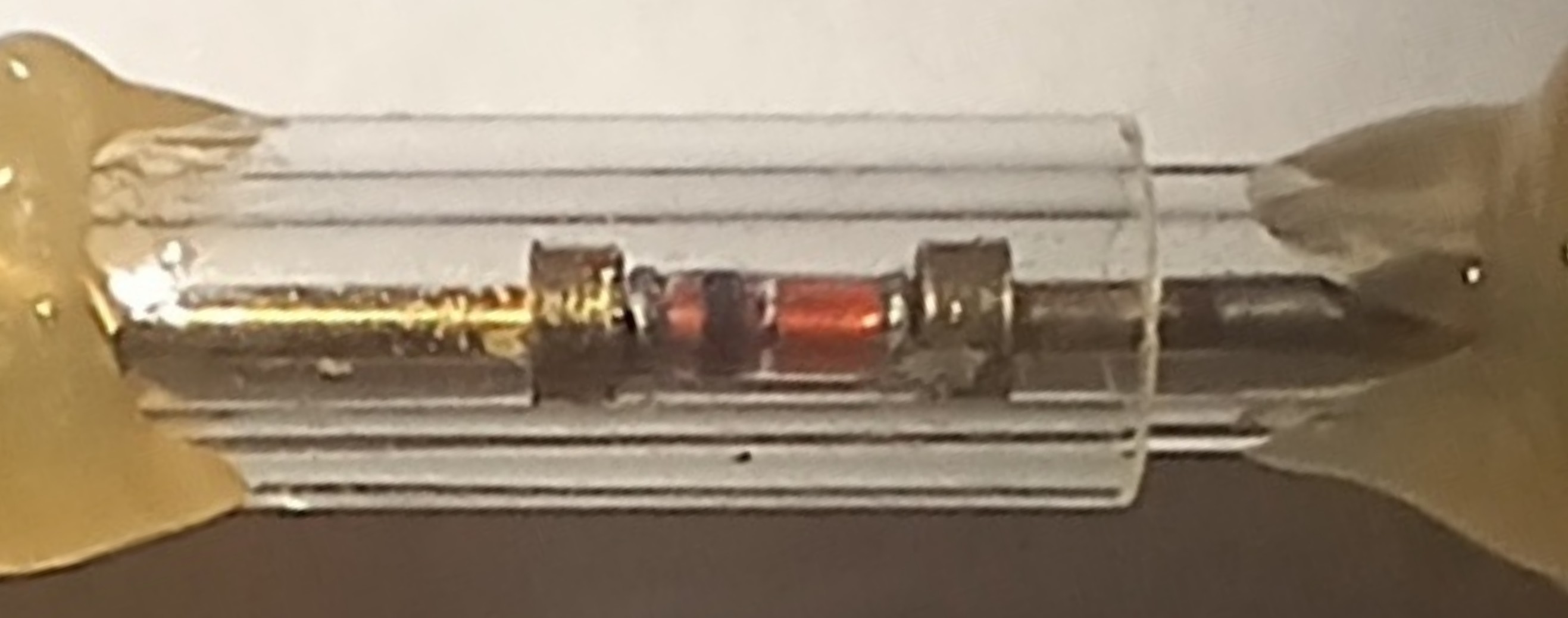
I made a jig for easily measuring Minimelf packages. The glass tubes were taken from incandescent light bulbs. I also used SMA connectors (male and female) and spring test probes. I attached the tubes to the SMA connector and the spring test probe using epoxy resin. I could have skipped the connectors and soldered the cables directly, but I was worried that the cable might break one day.


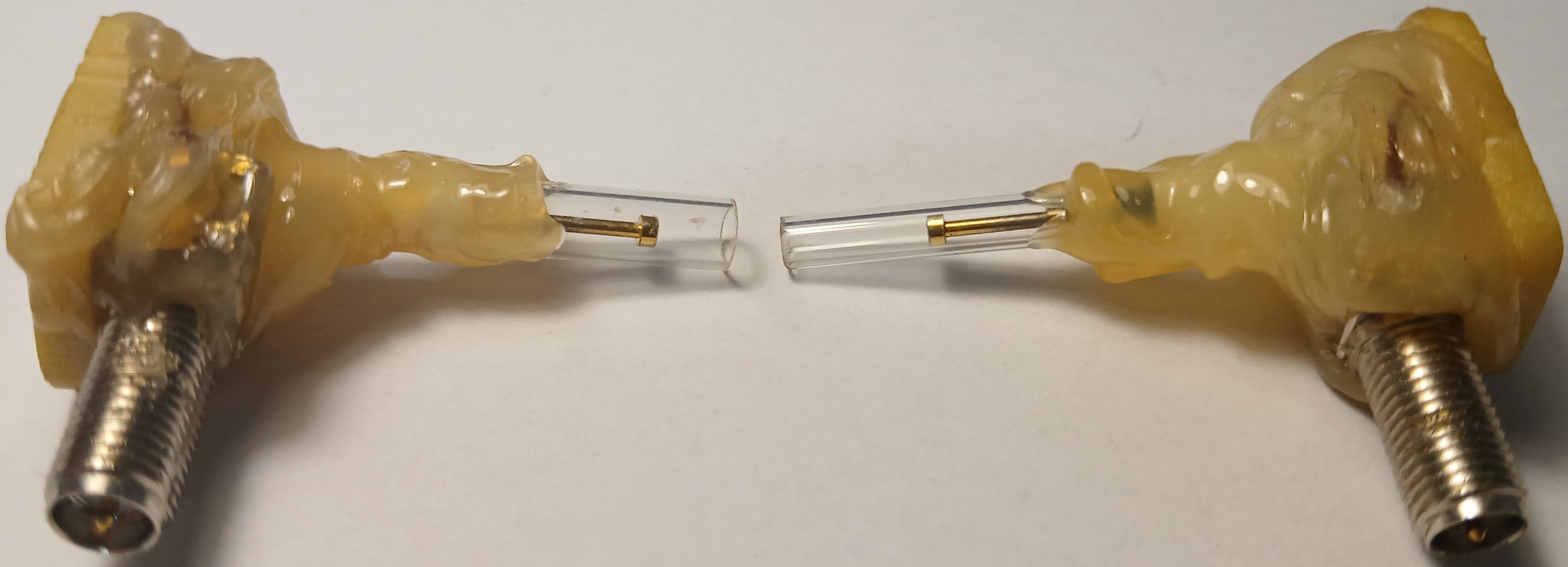
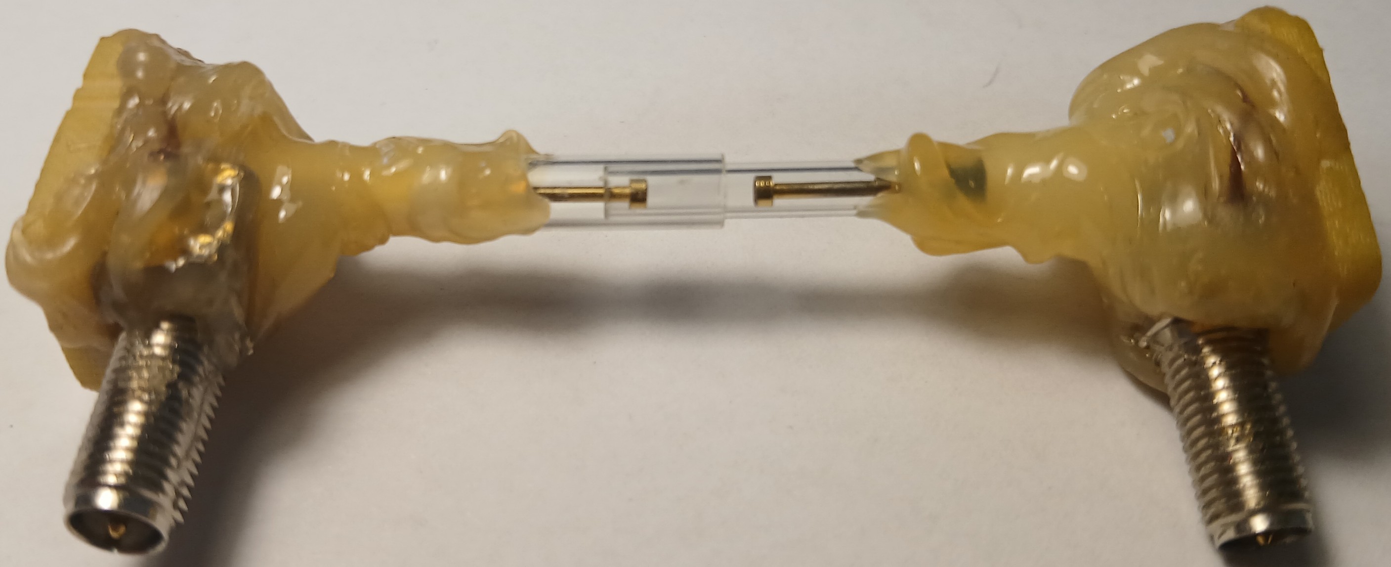
                                                                    With Minimelf package.


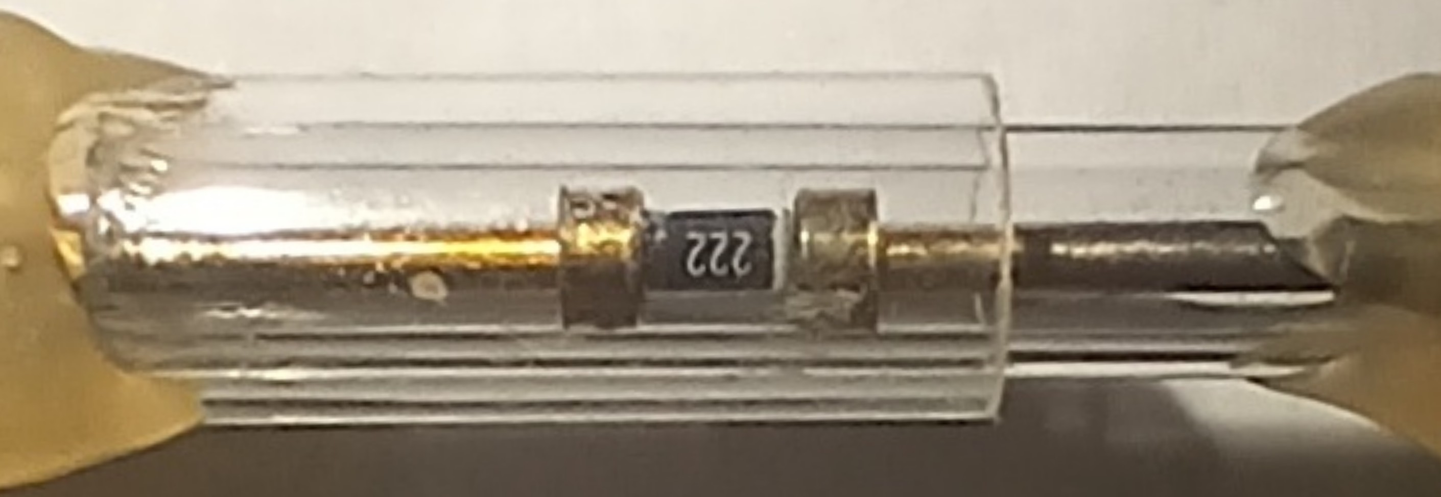
                                                                With resistor 0805 package.

You can probably use ready-made Current Regulator Diodes such as the 1N5283-1 through 1N5314-1, J500 SERIES current regulating diodes, and similar types. I haven't used them because they are expensive and hard to find. I invite readers to share their opinions.

LINKS : Calculation of R1 , ods format

            Calculation of R1 , xlsx format

            Infineon's Application Note for Depletion MOSFETs

            DN2540 datasheet


A simple but very useful Zener diode tester

A simple but very useful Zener diode tester

25
 
1
0
0

Share your project on social media to expand its influence! Get more people to support it.

  • Comments( 0 )
  • Like( 1 )
/1000
Upload a photo:
You can only upload 1 files in total. Each file cannot exceed 2MB. Supports JPG, JPEG, GIF, PNG, BMP

You May Also Like

View All
Add to cart
Board Type : GerberFile :
Layer : Dimensions :
PCB Qty :
Different PCB Design
PCB Thickness : PCB Color :
Surface Finish : Castellated Hole :
Copper Weight : 1 oz Production Time :
Total: US $
As a sharing platform, our community will not bear responsibility for any issues with this design and parameters.

PCB Assembly

PCBA Qty: BomFile:
NO. OF UNIQUE PARTS: NO. of Components:
Country: Shipping Way:
Assembly Cost: US $
As a sharing platform, our community will not bear responsibility for any issues with this design and parameters.
Add to cart
3dPrintingFile : Size :
Unit : Volumn :
3D Printing Qty : Material :
Total: US $12.99
As a sharing platform, our community will not bear responsibility for any issues with this design and parameters.
Add to cart
Acrylic Type : AcrylicFile :
Dimensions: Engrave:
Acrylic Qty :
Acrylic Thickness:
Acrylic Color:
Total: US $12.99
As a sharing platform, our community will not bear responsibility for any issues with this design and parameters.
Add to cart
CNC Milling File : Size:
Unit: Volumn:
CNC Milling Qty : Material:
Type of Aluminum: Surface Finish:
Tolerance:
Surface Roughness:
Total: US $12.99
As a sharing platform, our community will not bear responsibility for any issues with this design and parameters.
Add to cart
Item Price Qty Subtotal Delete
Total: US $0.00
Certified Product | Guaranteed Purchase: Full techsupport