Currency
Toggle Nav



pic0rick
Special Price
$299.00
Availability:
In stock
SKU
PDA26051P
Weight
80g
it's an open source ultrasound pulse-echo device.. 60Msps, up to 55.5 dB variable gain, high precision bipolar pulser control at +-24V.
Frequently Bought Together

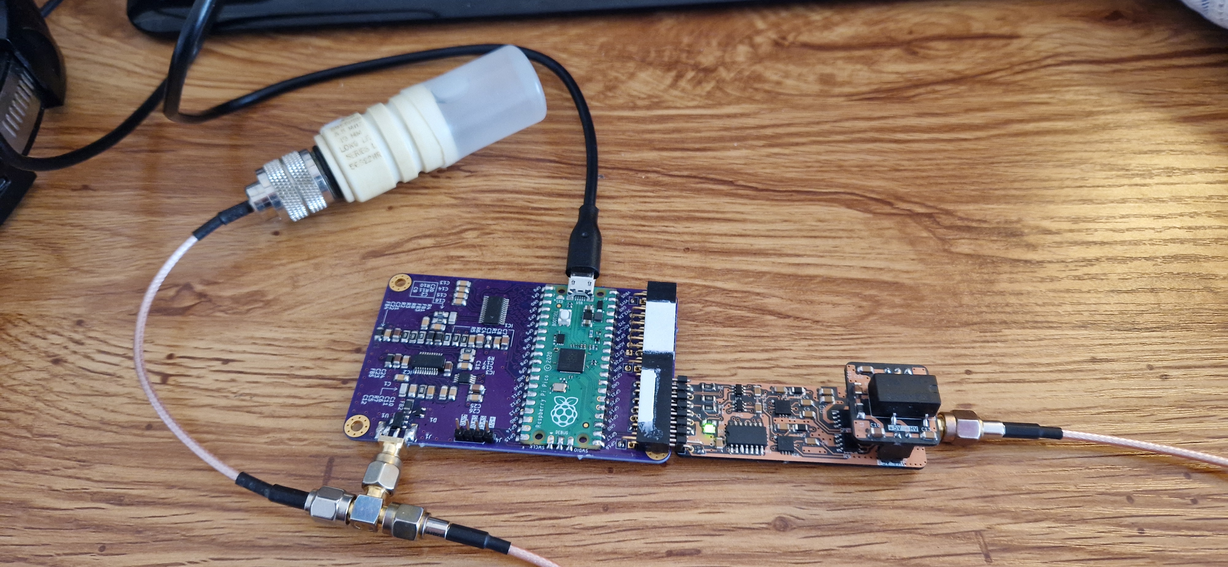
The pic0rick
TLDR: it's an open source ultrasound pulse-echo device.. 60Msps, up to 55.5 dB variable gain, high precision bipolar pulser control at +-24V.
The pic0rick is the current recommended board in the un0rick family. It replaces the FPGA-based designs with an RP2040/RP2350 microcontroller, delivering comparable ultrasound acquisition performance at a fraction of the cost and complexity — with no FPGA toolchains or specialized hardware knowledge required.
New to the project? Start with the Getting started guide for a step-by-step walkthrough from unboxing to your first echo.
Specifications
| Parameter | Value |
|---|---|
| Microcontroller | RP2040 (dual-core Cortex-M0+, 133 MHz). RP2350 also supported |
| ADC | 60 Msps, 10-bit resolution |
| TGC amplifier | AD8331 — 7.5 dB to 55.5 dB variable gain |
| TGC control | MCP4812 SPI DAC |
| Pulse generation | Three-level pulser via MD1210 + TC6320 (on pulser PMOD board) |
| Pulse voltage | +-25 V (via HV generation board) |
| Input protection | HV clipping on receive path |
| PMOD connectors | 1x single (pulser), 1x double (VGA, MUX, PSRAM, or custom) |
| Data interface | USB (serial) |
| PIO usage | PIO0: acquisition timing, PIO1: VGA output (when connected) |
| Power | USB bus powered |
| Design files | KiCad (open source) |
| Firmware | C/C++ for RP2040 — Arduino-like development environment |
| Certification | OSHWA open-source hardware certified |
System architecture
The pic0rick is a modular three-board system:
Main board — The core of the system. Contains the RP2040 microcontroller, the 60 Msps 10-bit ADC, the AD8331 TGC amplifier with SPI-controlled gain curve, and HV input protection on the receive path. The main board hosts both PMOD connectors and the USB interface.
Pulser board (single PMOD) — Generates the transmit pulse on behalf of the main board. Uses a pair of MD1210 + TC6320 to produce three-level pulses. Requires the HV board for high-voltage supply.
HV board — A simple +-25V generation board that plugs into the pulser board. Provides the high-voltage rail needed for pulse generation.
The signal chain works as follows:
``` RP2040 → PIO triggers pulse → Pulser board → Transducer
Transducer → Echo returns → HV protection → AD8331 TGC → 60 Msps ADC → RP2xxx → USB → Computer ```
The RP2040's two PIO units are used for precise timing: one drives the acquisition sequence (pulse trigger + ADC sampling), and the other can do something else (say drive a VGA output for real-time visualization) — leaving the two Cortex-M0+ cores free for your own application code.
How does it replace the FPGA?
Previous boards (un0rick, lit3rick) used a Lattice iCE40 FPGA for precise timing control of the pulse-echo sequence. The pic0rick achieves the same timing precision using the RP2040's Programmable Input/Output (PIO) state machines. PIO programs run deterministically at the system clock rate, providing the sub-microsecond timing needed for ultrasound acquisition — without requiring HDL knowledge or FPGA synthesis tools.
This means you can modify the acquisition timing, pulse patterns, and sampling parameters by editing C code in a standard Arduino-like environment, rather than writing Verilog or VHDL and running a synthesis toolchain.
Board comparison
How does the pic0rick compare to the older un0rick-family boards?
| pic0rick | un0rick | lit3rick | lit3-32 | |
|---|---|---|---|---|
| Status | Active | Legacy | Legacy | Legacy |
| Years | 2024–now | 2018–2025 | 2020–2024 | 2021–2024 |
| Controller | RP2040 / RP2350 | iCE40 HX4K/HX8K | iCE40 UP5K | iCE40 UP5K |
| Type | Microcontroller | FPGA | FPGA | FPGA |
| ADC speed | 60 Msps | Up to 64 Msps | Up to 64 Msps | Up to 64 Msps |
| ADC resolution | 10-bit | 10-bit | 10-bit | 10-bit |
| TGC amplifier | AD8331 (48 dB range) | AD8331 (48 dB range) | AD8331 (48 dB range) | AD8332 (92 dB range) |
| Onboard HV | No (separate board) | Yes | No | No |
| Form factor | Compact + PMODs | Large single board | RPi pHAT | RPi pHAT |
| Programming | C/C++ (Arduino-like) | Verilog + Python | Verilog + Python | Verilog + Python |
| FPGA required | No | Yes | Yes | Yes |
| Extensible | PMOD connectors | Limited | RPi GPIO | RPi GPIO |
| Cost | Lowest | Medium | Low | Medium-high |
| Best for | New projects, education, fast prototyping | Users needing full FPGA flexibility | RPi-integrated setups | Weak signal detection (high gain) |
For new projects, we recommend the pic0rick unless you specifically need FPGA-level timing control or the 92 dB gain range of the lit3-32.
Example of acquisition
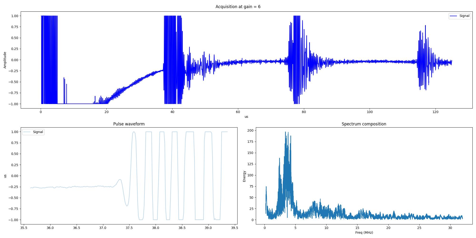
A typical acquisition looks like this — the large spike on the left is the transmit pulse, and the smaller peaks to the right are reflections from your target:
How to assemble it?
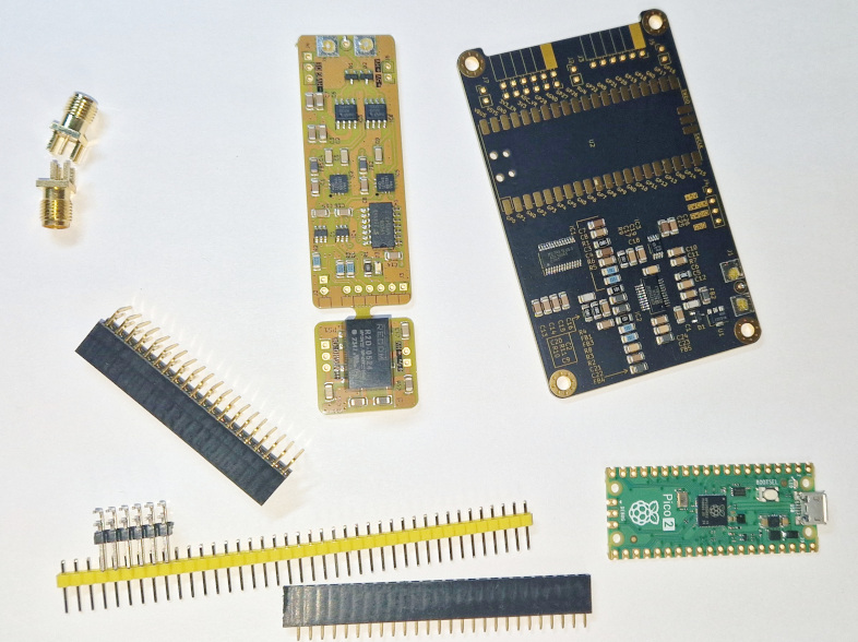
See at the end of this page, or at un0rick.cc/getting-started. You will receive the yellow board and the black board, and you can assembled them the way you want.
Other points
- It's open source, all is at :
- Hardware (KiCad): Main board, pulser board, HV board — in the pic0rick repository
- Firmware: RP2040 C/C++ source code — in the
software/directory -
Documentation: Published under CC BY-SA 3.0 in the pic0rick site
-
Find it:
- Buy the assembled PCBs (no header, connector, pico): Available on Tindie
- Build your own: All KiCad files and BOM are in the GitHub repository
Things to know before you buy:
- Now that the board design is stabilized, it's being produced by MacroFab - which does the fulfillment.
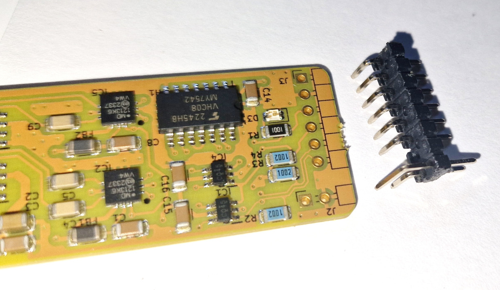
- Attention: The board comes without headers/jumpers/SMA/RPi .. up to you to put yours!
- The board does not come with a raspberry pi pico : bring your own:
- The boards come without any transducer / piezo (it's bring your own piezo)
- Beware of the taxes: the UPS/DHL courier may ask import taxes, depending on your country, as it is shipped from the US.
License
This work is based on three previous TAPR projects, the echOmods project, the un0rick project, and the lit3rick project — their boards are open hardware and software, developed with open-source elements as much as possible.
- The hardware is licensed under TAPR Open Hardware License (www.tapr.org/OHL)
- The software components are free software: you can redistribute it and/or modify it under the terms of the GNU General Public License as published by the Free Software Foundation, either version 3 of the License, or (at your option) any later version.
- The documentation is licensed under a Creative Commons Attribution-ShareAlike 3.0 Unported License.
Disclaimer
This project is distributed WITHOUT ANY EXPRESS OR IMPLIED WARRANTY, INCLUDING OF MERCHANTABILITY, SATISFACTORY QUALITY AND FITNESS FOR A PARTICULAR PURPOSE.
Also:
- This is not a medical ultrasound scanner! It’s a development kit that can be used for pedagogical and academic purposes - possible immediate use as a non-destructive testing (NDT) tool, for example in metallurgical crack analysis.
- As in all electronics, be careful, especially with high voltages.
- This is a learning by doing project, I never did something related -> It’s all but a finalized product.
-
Ultrasound raises questions. In case you build a scanner, use caution and good sense!
-
In all cases, I can and will help you work with the pic0rick boards, but I can't and won't teach you how to use and program a pico, nor could I handhold everyone to understand what NDT is =) But always happy to chat - feel free to reach out
The physical assembly of the device
What you get :
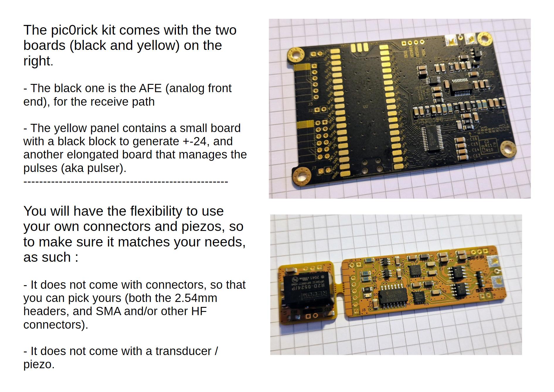
Before assembly
You will need to get a few headers, a raspberry pico, and SMA connectors
Focus on the Pulser connector
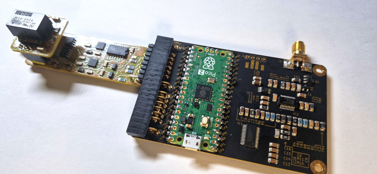
Once assembled
Top view
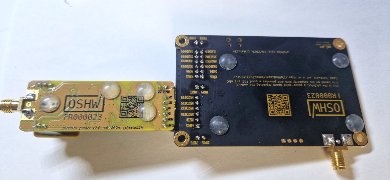
Bottom view
Write Your Own Review
Bestselling Products You May Like
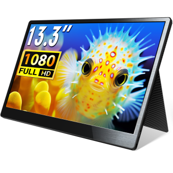
CrowVi VF133 HD 1920x1080 Ultra Thin Display 13.3inch IPS Portable Monitor (non touchscreen)
was
$114.90
Special Price
$99.90


New Products You May Want



Warranty
Service

VIP Distributor
Discount

Professional
Tech Support

Fast
Delivery
×
 Add to cart successfully!


Add to cart successfully!
Customers Who View This Item Also Bought