Story

For this Halloween, I'm fusing the creative blocky world of Minecraft with the spooky glow of the colorful RGB LEDs in a fun and simple Halloween project.
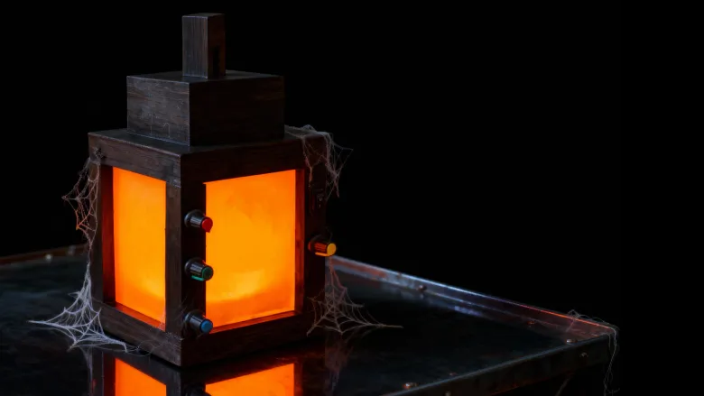
A "Color Adjustable Minecraft Lantern" is a project that recreates the iconic lantern from the video game Minecraft. It allows the user to change the light's color to any hue, rather than being limited to the standard yellow or orange glow.
Video: https://www.youtube.com/watch?v=8wauoKaCeak
Components Required

For this project we need:
- [Buy Now] 1 x Arduino Nano
- [Buy Now] 2 x WS2812B 16 LEDs NeoPixel Ring
- [Buy Now] 4 x 10kΩ Rotary Potentiometer
- [Buy Now] 1 x 1000µF capacitor is highly recommended to smooth out voltage spikes and dips
- [Buy Now] 1 x 100Ω Resistor placed in series on the data line to limit the current and dampen signal reflections
- [Buy Now] 1 x SPST Switch
- [Buy Now] 1 x 18650 Battery and a Holder
- [Buy Now] 1 x TP4056 Battery Charging Module
- [Buy Now] 1 x DC-to-DC Buck Converter
- Jumper Wires & Breadboard
- and a 3D printer to print the enclosure
Wiring Diagram

The setup consists of three simple circuits:
1. First, the power circuit: a battery that charges and runs the Arduino Nano
2. Second, the control circuit: a potentiometer feeding signal to the Arduino
3. And third, the light circuit: the NeoPixels, which lights up based on the instructions received from the Arduino
Explanation of operation:
The Arduino reads the potentiometers via its analog pins, generating values from 0 to 1023. This range is then mapped to 0-255 to comply with the Arduino library. The converted signal is then sent sequentially to the LEDs, lighting them up one by one from first to the last.
Two key components are required for signal integrity: a 1000µF capacitor closest to the load to stabilize the voltage, and a 100Ω resistor on the data line to protect against current surges and dampen signal noise.
[[In general, caps are for 3 things. To provide a reservoir of current to keep voltage stable, to bypass noise to ground and to pass AC signals while blocking DC. The third is of no use in this context, but the other 2 are. Higher value caps are used as reservoirs (ie.1000uF) and lower values to bypass noise (0.1uF, 1uF). As a rule of thumb, caps should be placed close to where the problem that they are to solve occurs]]
The Code

The code begins by including the Adafruit NeoPixel library and by defining the necessary pins and global variables.
In the setup() section, we initialize the NeoPixel library and immediately run a rainbow cycle across the entire LED ring to confirm it's working.
The loop() section continuously reads the potentiometer value, mapping it from a 0-1023 range to 0-255. You'll notice that I commented out the brightness control section. This is because, during my testing, I found that the NeoPixel library's brightness setting proportionally scales all RGB values, which significantly alters the LEDs' perceived color and intensity.
Important Considerations
Color Perception: Lower brightness can make colors appear different than expected
Power Consumption: Lower brightness = less power used
Heat Generation: Lower brightness reduces heat
Eye Comfort: Very bright NeoPixels can be uncomfortable to look at
Finally, the code uses the mapped potentiometer values to set the pixel colors and updates the LED display. This creates a direct, real-time control between the potentiometers and the LED output.
Breadboard Testing

Before putting everything into the enclosure, I hooked them up on a breadboard to test the code. When I power it on, you can see the NeoPixel rings plays a little rainbow animation, and then they are ready to go. Now, when I turn these knobs, the colors change smoothly as the Arduino reads the potentiometer values and updates the LEDs in real-time.
3D Design

I designed a custom 6-part enclosure in Microsoft 3D Builder for this project. You can download the STL files from my GitHub repository and have them professionally printed from elecrow.
The assembly includes:
1. A base for the main components like the battery, Arduino and the battery charger
2. A TP4056 stopper to secure the charging module
3. Four stands to mount the switch and potentiometers
4. Four Perspex panels to diffuse the LED light and hide the electronics
5. Two stand covers to conceal the sides
6. And a top lid to finish the enclosure
After finalizing the design, I proceeded to 3D print all the required components for the assembly. These are all the custom components I'll need to assemble the final unit.
Assembly

With all the 3D models printed, I began assembling the electronic components.
I soldered wires to each potentiometers and the SPST switch, then mounted them into their designated stands. Each potentiometer was secured by tightening its screw, with its wires routed through a small hole in the side of the stand. Similarly, the switch was pressed into its hole, and its wires were fed through the corresponding wire channel.
Next, I focused on the battery charging bit of the circuit. I soldered the battery to the B+ and B- ports of the TP4056 charging module. A blue wire was used to connect the OUT- of the TP4056 to the VIN- of the buck converter, while the SPST switch was wired to control the connection between the OUT+ and VIN+ terminals.
Once these connections were complete, I installed the power components into the base of the unit. The TP4056 module was secured by supergluing a stopper behind it after sliding it into place, and I also super glued the stand holding the on-of switch to the base.
For the control system, I soldered all the necessary components for the Arduino onto a perfboard. While the setup may appear messy, the final assembly will be fully enclosed. I then hot-glued the two NeoPixel rings into position, the first one to the base and the second one to the top. After supergluing the 2nd stand I concealed the electronics by supergluing the 'side covers' to it.

Before installing the perspex panels I painted the body of the lantern with black acrylic color. After the paint dried, I inserted the perspex panels and superglued the top into place to complete the build.
Demo

So, this is how my final setup looks like.
This is a classic way to create an interactive project where you turn a knob to change the behavior of the lights. The microcontroller reads the potentiometer's position, converts it to a value, and then uses that value to change something about the NeoPixels (e.g., brightness, color or speed).
This project encourages children to experiment with the primary colors to see what new shades they can create.
Let me know what you think.
Feel free to like, share, and comment if you have any suggestions for improvement!
Thanks
Thanks again for checking my post. I hope it helps you.
If you want to support me subscribe to my YouTube Channel: https://www.youtube.com/@CrazyCoupleDIY
- Video: https://youtu.be/8wauoKaCeak
- Full Blog Post: https://diyfactory007.blogspot.com/2025/10/Minecraft-Lantern.html
- Github: https://github.com/tarantula3/RGB-Minecraft-Lantern
Support My Work
- BTC: 1Hrr83W2zu2hmDcmYqZMhgPQ71oLj5b7v5
- LTC: LPh69qxUqaHKYuFPJVJsNQjpBHWK7hZ9TZ
- DOGE: DEU2Wz3TK95119HMNZv2kpU7PkWbGNs9K3
- ETH: 0xD64fb51C74E0206cB6702aB922C765c68B97dCD4
- BAT: 0x9D9E77cA360b53cD89cc01dC37A5314C0113FFc3
- LBC: bZ8ANEJFsd2MNFfpoxBhtFNPboh7PmD7M2
- COS: bnb136ns6lfw4zs5hg4n85vdthaad7hq5m4gtkgf23 Memo: 572187879
- BNB: 0xD64fb51C74E0206cB6702aB922C765c68B97dCD4
- MATIC: 0xD64fb51C74E0206cB6702aB922C765c68B97dCD4
Thanks, ca again in my next tutorial.