Story
Laboratory power supply 0 to 32 volts with tester
Full description:

This project consists of two parts:
1- Power supply
2- Tester

POWER SUPPLY:
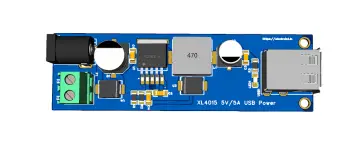
The power supply uses the XL4016 module
Which includes two parts for controlling voltage and current
These two pieces are 10k ohm variable resistors with the number 103
To use in the panel, first remove these two pieces and prepare two multi-turn potentiometers.

 Instead of the variable resistor pins,
solder 3 wires each. Note that the pins are
numbered 1-2-3, where 1 and 3 are the
beginning and end of the variable resistor,
and pin 2 is the moving head that creates
the changes. These three wires are in order here
Now on your 10-turn variable resistor, there are three pins, which are not in order here. From the end of the potentiometer, first wire 2, which means the variable output, and then 1 and 3, be careful when soldering them and solder each number in its place.
This is for voltage control, and to control current I used a regular 10k variable resistor. In this type of resistor, the two side ends are 1 and 3, and the middle end, which is variable, is 2, which is exactly the same as the potentiometers on the board. Note that for both voltage and current, you can use a 10k multi-turn or regular potentiometer, but when using a regular potentiometer, the adjustment accuracy is reduced and it is difficult to adjust the exact values. However, since multi-turn potentiometers are more expensive, they offer you precise and convenient adjustment. In order to be both accurate and economical, I used a multi-turn potentiometer to adjust the voltage, which is more needed, and a regular potentiometer to adjust the current.

On the board, you will see an LED in the middle of the four electrolytic capacitors.
Take out this LED as well.

This LED is a three-pin LED, in which the middle pin is + and the two side pins are -, the flat pin and one of the pins lights up, and the middle pin and the other lights up green.
Well, the function of this LED is to display the current with addition. When the output current is less than the current of your load, this LED turns red, and when the output current of the power supply is sufficient for our load, this LED turns green.

On the board, look at it from the back so that the potentiometers are on your right, from left to right, the first pin of the LED line is positive for green, the middle pin is negative, and the right pin is positive for red.

In this project, instead of this double LED, I have used two 5 mm green and red LEDs, so for this, R is connected to the red LED and G to the green LED, and the common middle pin is connected to both LEDs.
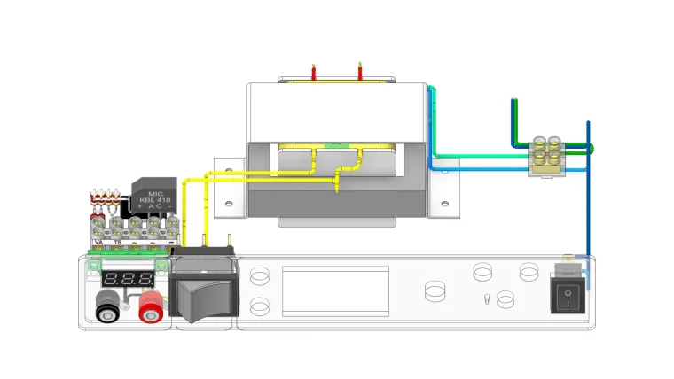
 To power the board, I used a 24V
Siemens transformer just because it was
smaller and fit in my box. If you use another
transformer, make sure you don't have any
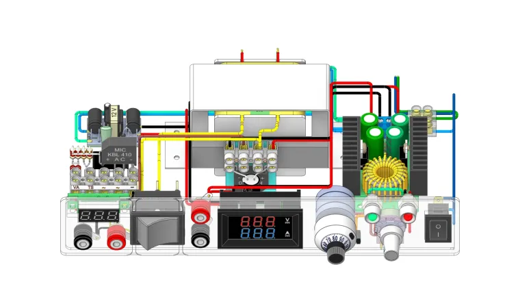
problems fitting it in the box. For rectification,
I used a diode bridge and a 1000 micro 35V
capacitor, and its output provides a 0-32V
supply. Well, you might ask, the transformer input is 24V, so how do I get a 0-32V output? Note that the AC24 voltage of the transformer, when it passes through the regulator and is rectified, is added by the radical of 1.7 for each internal diode (4 internal diodes), so my output reaches the desired value.
2-Tester
Those who work with electronics need a useful tool at their fingertips that can tell you how many volts this component works with.
For example, the voltage needed to turn on a red LED is different from the voltage needed to turn on a blue LED. You might say, no, we turn on both with 2.5 volts. No, I mean, if we want both to light up with the same brightness, we need to get their correct voltage. Now I need a circuit that can tell me these things.
To solve this problem, I used the law of series resistances, that is, I have a voltage of 32 volts, I put a 1.65 K 1/2 W resistor at the output.
This resistor can withstand 32 volts perfectly. Well, nothing special has happened so far. Now, I connect a voltmeter to the negative end and the resistor end. The voltage shown is equal to my source, that is, 32 volts.
Now, if I connect the negative end to the resistor, the two ends of my voltmeter are shorted and show zero volts. Now, if the negative is connected to an LED and The other end of the LED is connected to the resistor. The LED will take the amount of voltage it needs and the rest will be on the internal 1.65k resistor. In this case, since the voltmeter is connected to both ends of the LED, it tells us how many volts the LED needs. We have reached the answer.
Now, to make a 1.65k resistor with 1/2 watts, instead of one resistor, I used two 3.3k resistors, each quarter watt. I connected these two in parallel, which halves their value, we get 1.65k 1.2 watts.

To power the voltmeter, we need 2.2K 1 W, so I used four 2.2K 1/4 W resistors, both of which are connected in parallel, and in total, these two are connected in series.

Now we have the general diagram of the tester.


with which we can obtain the voltage of the types of LEDs or the value of the following diodes, and in some cases, we can identify burnt out LEDs in LED lamps.

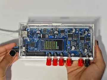
 Well, so far, both the 0-32V module
and the tester are ready. Each of these
only requires one voltage input.
Instead of two voltage inputs,
in other words, two transformers,
 I used one transformer and added a toggle switch.
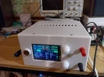
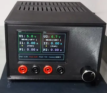
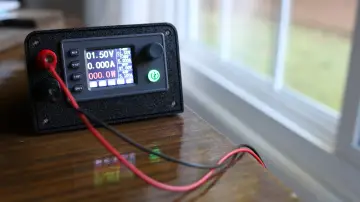
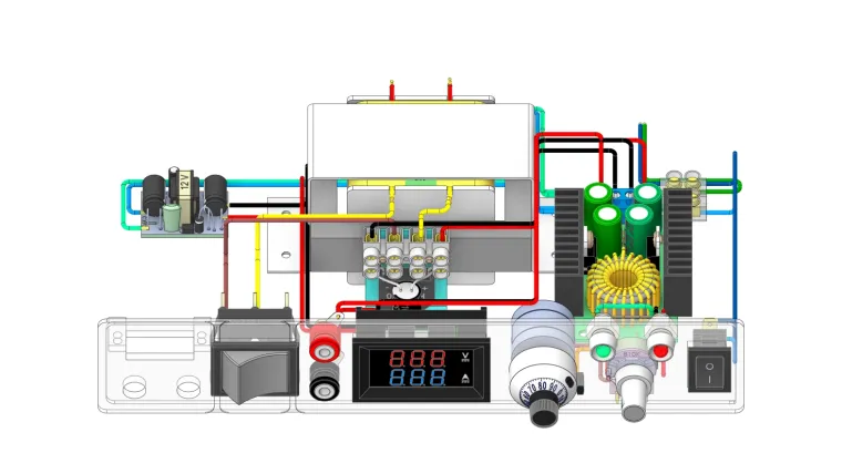
In order to be able to see the
output voltage and current,
we add a 0-100V voltage and
0-10A current display.
A 220 to 12V converter can be used to power it.
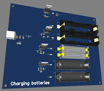
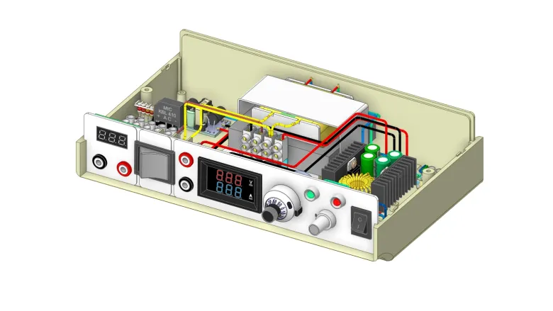
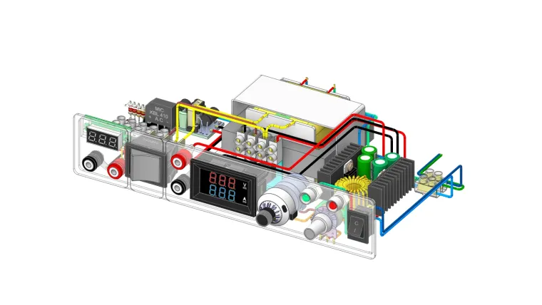
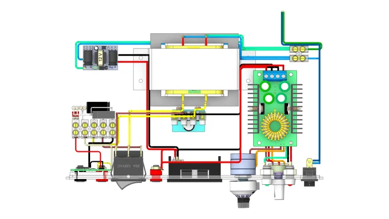
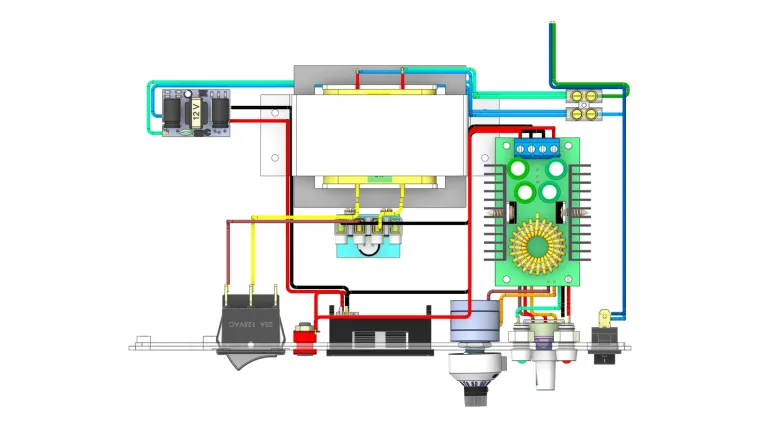
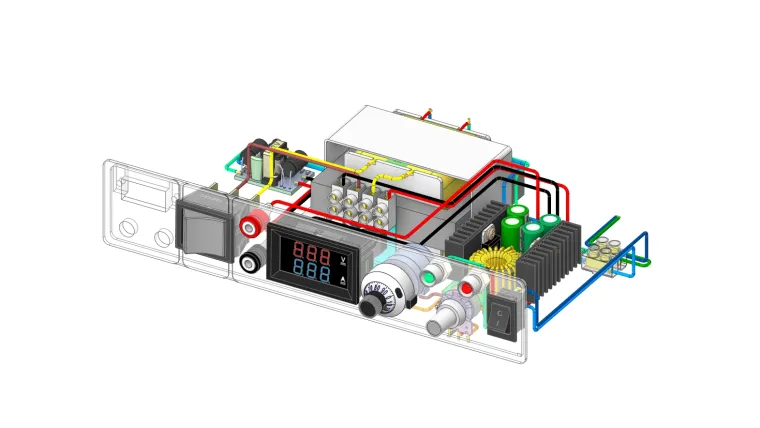
In this section you can see the complete map.

Schematic of a 3D design made from a power supply