
Story
At the pinnacle of industrial artificial intelligence and machine learning applications, a digital twin represents a virtual construction of real-world physical products, mechanisms, or mechanical procedures. Since the simulation of a real-world product or industrial technique provides the flexibility of exerting countless examination scenarios, even to the point of cycling arduous or dangerous tasks, without causing any tangible ramifications and safety risks, digital twins hold immeasurable importance in developing adaptive product manufacturing procedures and building secure, cost-effective, and efficient industrial facilities.
After inspecting recent research papers about the applications of digital twins in industrial operations, I noticed the focal point of employing a virtual representation is to improve the safety and efficiency of an already existing industrial facility or mechanical process. Even though forestalling acute physical hazards due to dangerous work safety risks and advancing the precision of ongoing industrial operations are the prominent digital twin use cases, I wanted to explore the innovative opportunities of reversing the digital twin implementation and starting with a virtual industrial construction, consisting of individual machinery and sample product components, to develop a safe, practical, cost-effective, and efficient real-world mechanism from scratch.
By reversing the digital twin application process, I wanted to investigate whether having a virtual construction before building the real-world counterpart could help to forfend concomitant risks of assembling an industrial manufacturing system, reduce exorbitant overhaul costs due to the lack of internal design blueprints, and test device components to obtain the optimum performance for multifaceted operations.
As I was conceptualizing this proof-of-concept project, I inspected various industrial settings with which I could show the benefits of reversing the digital twin implementation. Since product transportation and shipping operations require complex industrial mechanisms to achieve accuracy and reliability while maintaining a time-sensitive workflow, I decided to apply my reverse digital twin approach to design a virtual shipping workstation, construct a synthetic data set of customized sample products, and train a precise object detection model to accomplish building a production-ready product transportation mechanism. In accordance with my approach, I designed all sample products from scratch to emphasize the strengths of a full-fledged digital twin, providing the opportunity to train an object detection model for products waiting to be manufactured.
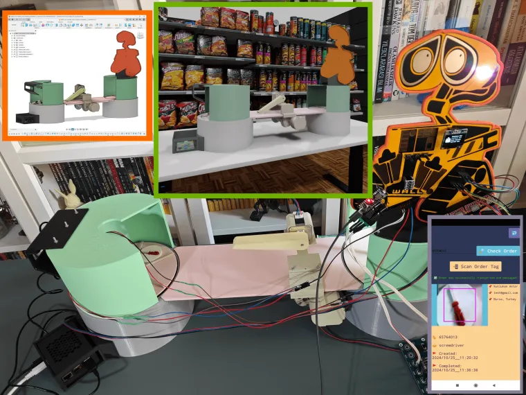
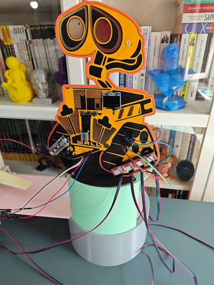
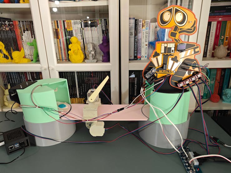
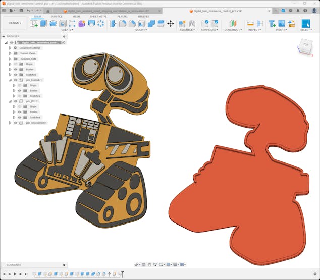
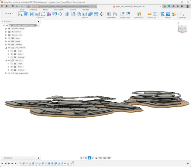
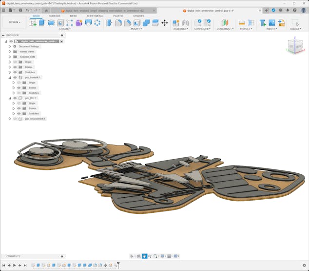
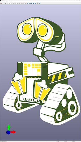
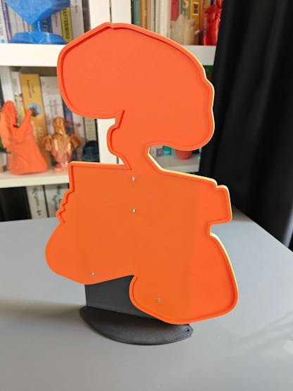
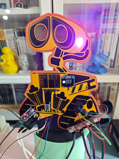
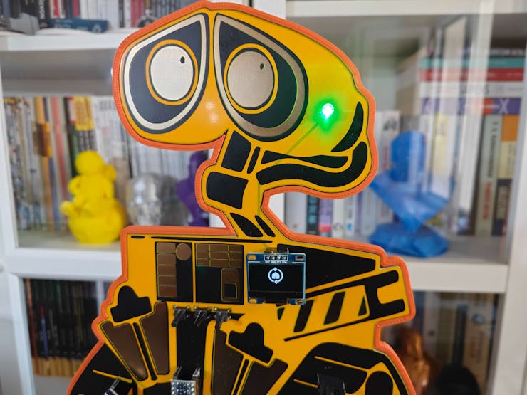
Since I needed to know the exact electronic components employed by the shipping workstation to create compatible 3D parts, I decided to prototype the mechanical device structure and design a unique PCB (inspired by Wall-E) based on Arduino Nano Matter as the workstation control panel. I designed the Wall-E PCB outline and encasement on Autodesk Fusion 360 to place the electronic components in relation to the PCB easily while designing the virtual shipping workstation.
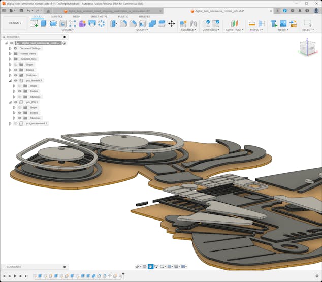
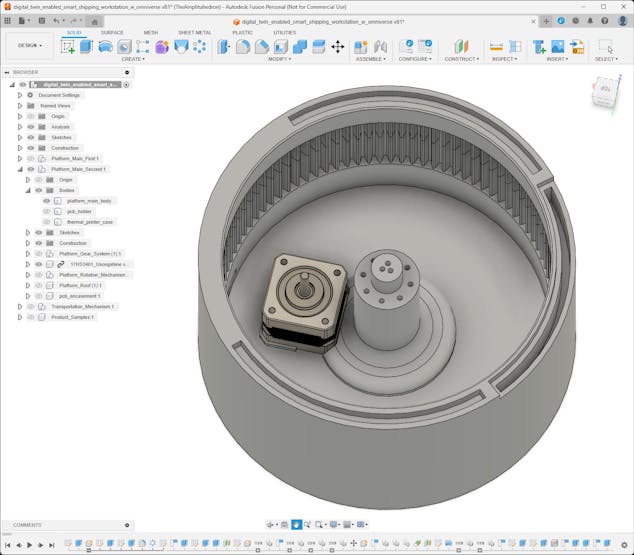
After testing electronic components and completing the PCB layout, I designed a plethora of 3D parts on Autodesk Fusion 360, including but not limited to custom bearings optimized for 5 mm steel balls, planetary gear mechanisms, and separated rotating platforms. After finalizing the required mechanical 3D parts, I exported the virtual shipping workstation as a single file in the OBJ format to produce an accurate virtual representation of the shipping workstation.
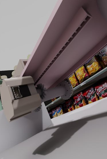
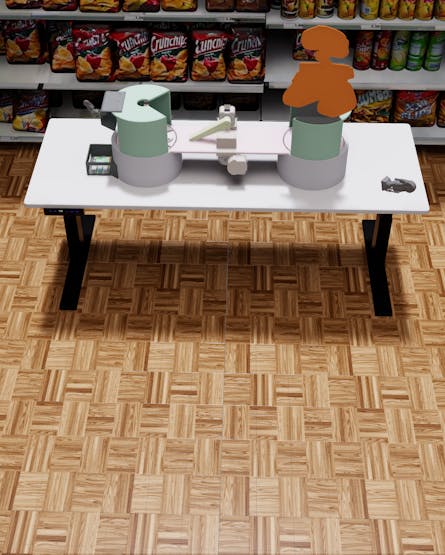
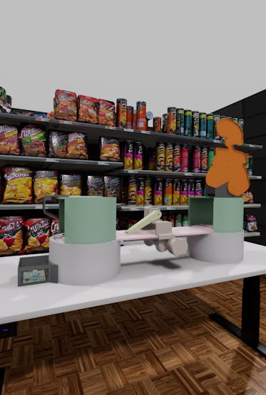
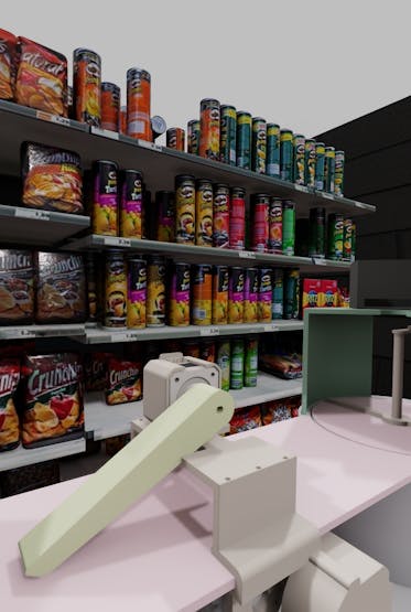
Then, I imported the virtual shipping workstation into the NVIDIA Omniverse USD Composer, which allows users to assemble, light, simulate, and render large-scale scenes for world-building. To generate a realistic scenery for shipping operations, I utilized some free 3D models provided by Omniverse and designed some additional assets. After completing my shipping warehouse scenery, I experimented with camera, material, and lighting configurations to render the virtual shipping workstation with exceptional quality and produce a precise digital twin.
After employing built-in NVIDIA Omniverse features to construct my synthetic data set of customized sample products as instantiated by the shipping workstation digital twin, I uploaded the collected samples to Edge Impulse to train an advanced object detection model (FOMO) with synthetic product images. After validating and testing my FOMO model, I deployed it as a Linux (AARCH64) application (.eim) compatible with Raspberry Pi 5.
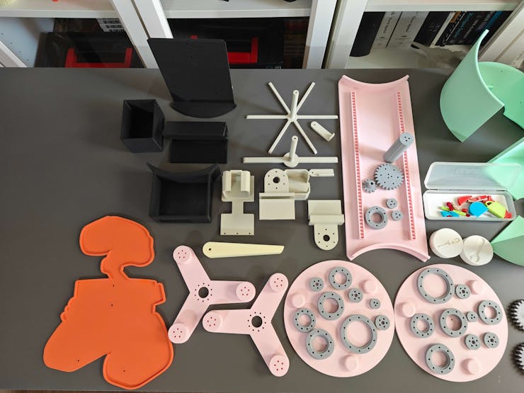
After building my object detection model successfully and completing my assignments with the shipping workstation digital twin on NVIDIA Omniverse, I started to print all workstation 3D parts to assemble the real-world counterpart.
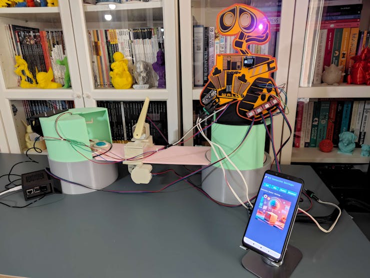
To create a fully functioning smart shipping workstation with state-of-the-art features, I developed a web application from scratch to manage the MariaDB database server hosted by Raspberry Pi 5, run the Edge Impulse FOMO object detection model, and transfer the detection results with the modified model resulting images. I also developed a mobile application (Android) operating as the workstation interface and the proxy between the workstation control panel (based on Arduino Nano Matter) and the web application.
So, this is my project in a nutshell 😃
Please refer to the following tutorial to inspect in-depth feature, design, and code explanations.


Design process, available features, and final results
As my projects became more intricate due to complex part designs, multiple development board integrations, and various features requiring interconnected networking, I decided to prepare more straightforward written tutorials with brevity and produce more comprehensive demonstration videos showcasing my entire design process, results, and device features from start to finish.
Thus, I highly recommend watching the project demonstration videos below to inspect my design process, the construction of the synthetic data set, and all of the shipping workstation features.
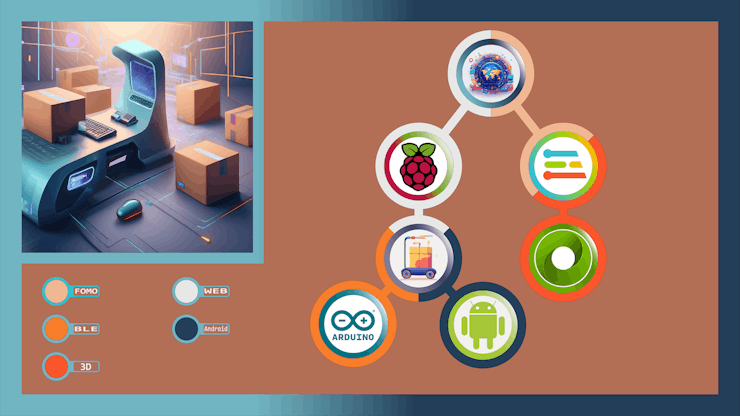
Step 0: A simplified illustration of interconnected networking
As a part of preparing a more visually-inclined tutorial, I decided to create a concise illustration of interconnected networking infrastructure to delineate the complicated data transfer procedures between different development boards, complementary web, and mobile applications.
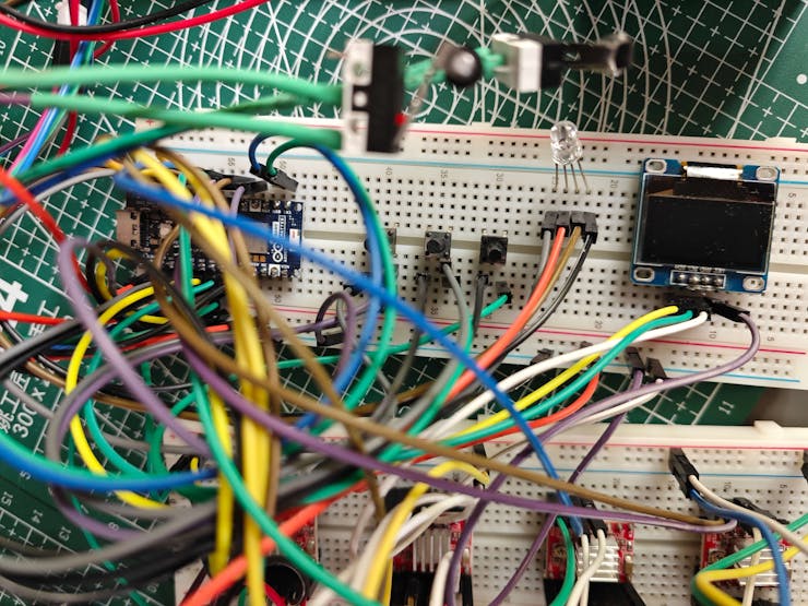
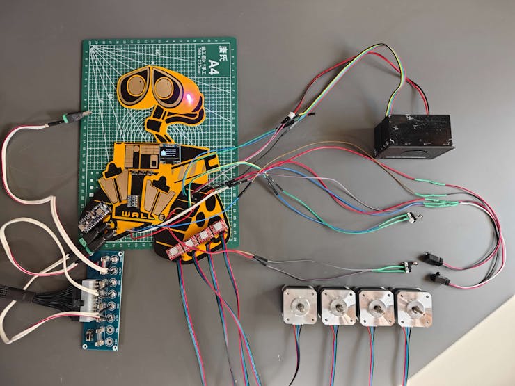
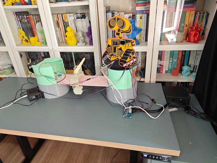
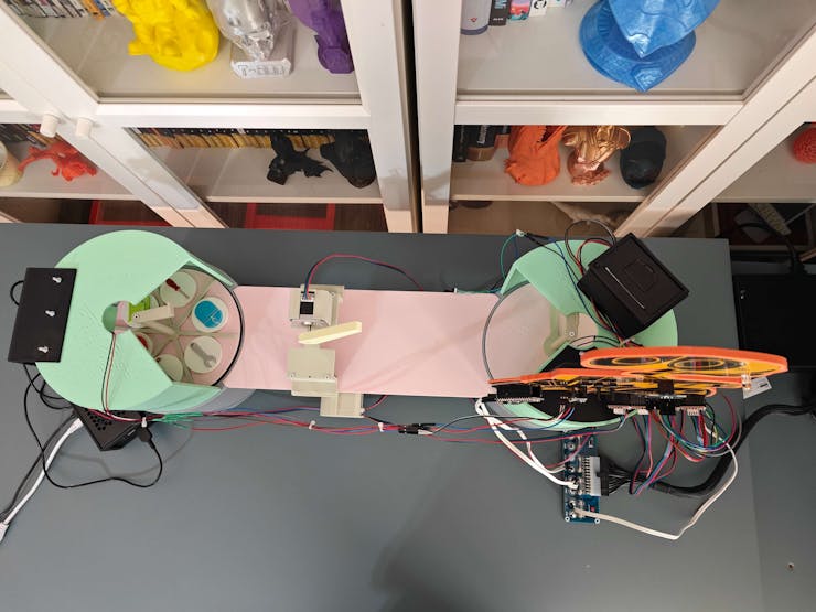
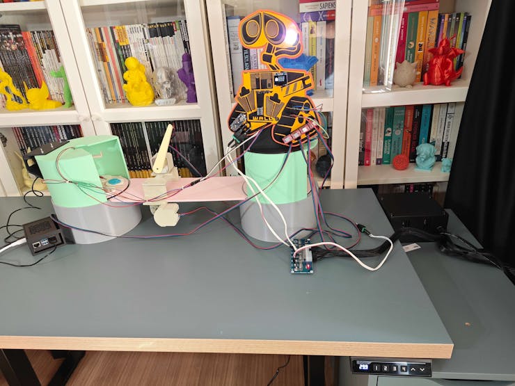
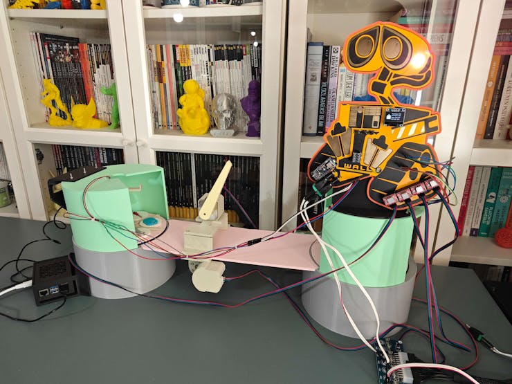
Step 1: Testing electronic components and prototyping the device structure
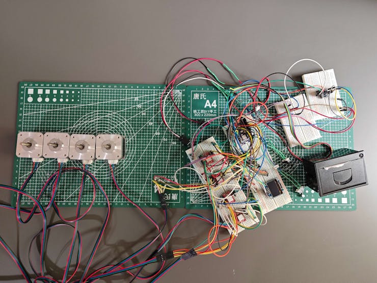
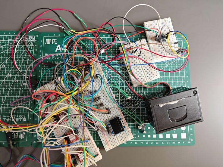
Before proceeding with designing 3D parts, I needed to determine all electrical components required to operate the real-world shipping workstation. Thus, I started to test and prepare electronic components for prototyping the device structure.
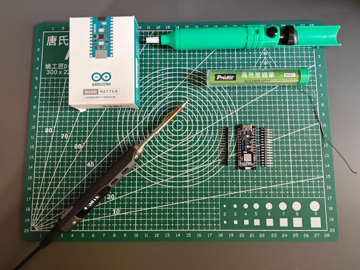
#️⃣ Since Arduino Nano Matter is a versatile IoT development board providing state-of-the-art Matter® and Bluetooth® Low Energy (BLE) connectivity thanks to the MGM240SD22VNA wireless module from Silicon Labs, I decided to base the shipping workstation control panel on Nano Matter.
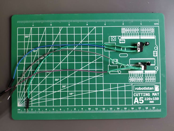
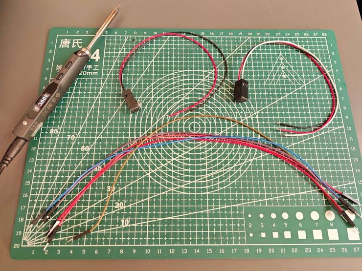
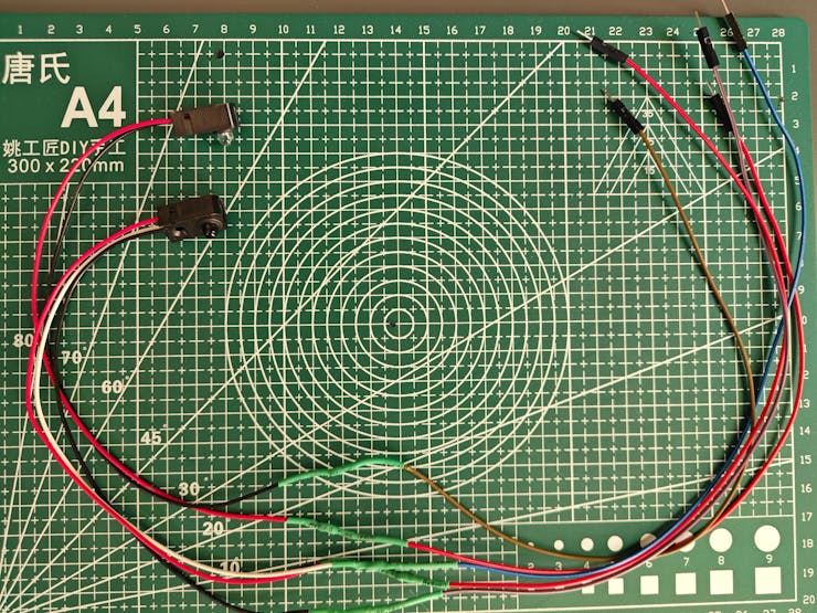
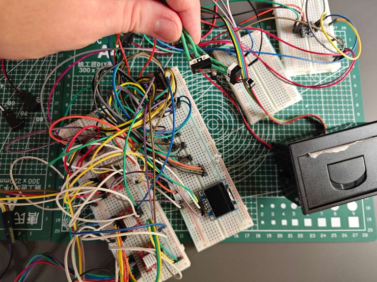
#️⃣ Since I envisioned a fully automated homing sequence for the moving workstation parts, I decided to utilize an IR break-beam sensor (300 mm) and two micro switches (KW10-Z5P).
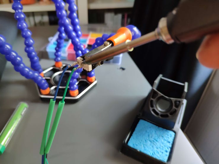
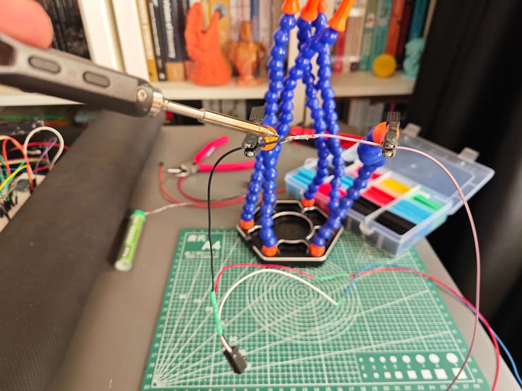
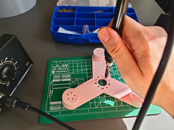
#️⃣ By utilizing a soldering station for tricky wire connections, I prepared the mentioned components for prototyping.
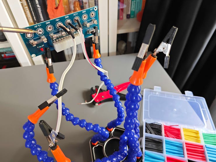
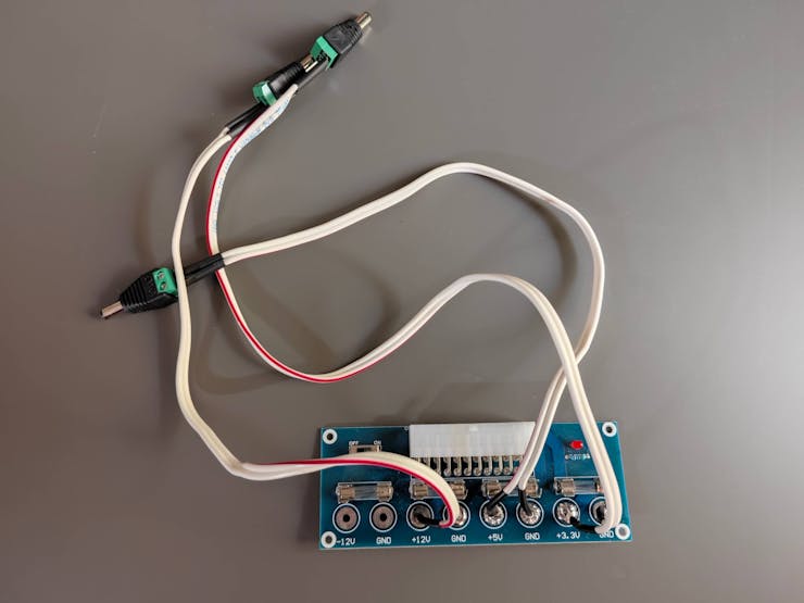
#️⃣ Since I needed to supply a lot of current-demanding electronic components with different operating voltages, I decided to convert my old ATX power supply unit (PSU) to a simple bench power supply by utilizing an ATX adapter board (XH-M229) providing stable 3.3V, 5V, and 12V. For each power output of the adapter board, I soldered wires via the soldering station to attach a DC-barrel-to-wire-jack (male) in order to create a production-ready bench power supply.
#️⃣ Since Nano Matter operates at 3.3V and the IR break-beam sensor requires 5V logic level voltage to generate powerful enough signals for motion detection, the sensor cannot be connected directly to Nano Matter. Therefore, I utilized a bi-directional logic level converter to shift the voltage for the connections between the IR sensor and Nano Matter.
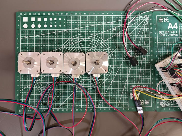
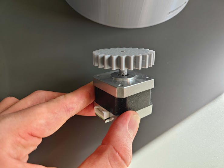
#️⃣ Since I planned to design intricate gear mechanisms to control the moving parts of the real-world shipping workstation, I decided to utilize four efficient and powerful Nema 17 (17HS3401) stepper motors, similar to most FDM 3D printers. To connect the Nema 17 stepper motors to Nano Matter securely, I employed four A4988 driver modules.
#️⃣ As a practical shipping workstation feature, I decided to connect a tiny (embedded) thermal printer to Nano Matter to print a shipping receipt for each completed order. I utilized a sticker paper roll to make receipts fastenable to cardboard boxes.
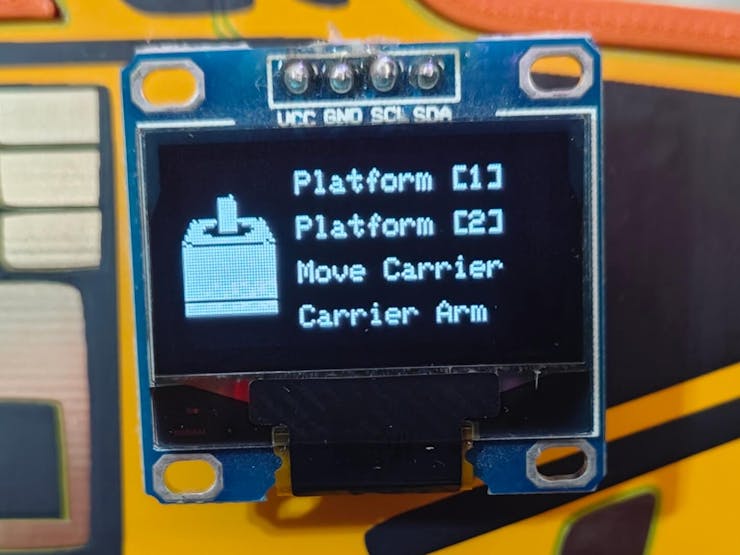
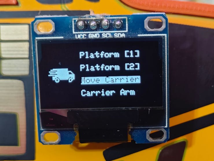
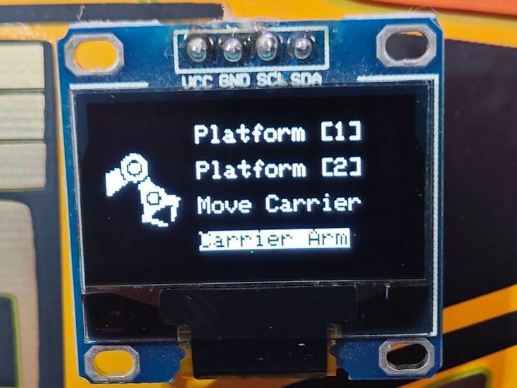
#️⃣ To build a feature-packed and interactive workstation control panel, I also connected an SSD1306 OLED display, three control buttons, and an RGB LED to Nano Matter.
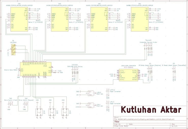
#️⃣ As depicted below, I made all component connections according to available and compatible Arduino Nano Matter pins.
// Connections
// Arduino Nano Matter :
//                                Nema 17 (17HS3401) Stepper Motor w/ A4988 Driver Module [Motor 1]
// 3.3V    ------------------------ VDD
// GND     ------------------------ GND
// D2      ------------------------ DIR
// D3      ------------------------ STEP
//                                Nema 17 (17HS3401) Stepper Motor w/ A4988 Driver Module [Motor 2]
// 3.3V    ------------------------ VDD
// GND     ------------------------ GND
// D4      ------------------------ DIR
// D5      ------------------------ STEP
//                                Nema 17 (17HS3401) Stepper Motor w/ A4988 Driver Module [Motor 3]
// 3.3V    ------------------------ VDD
// GND     ------------------------ GND
// D6      ------------------------ DIR
// D7      ------------------------ STEP
//                                Nema 17 (17HS3401) Stepper Motor w/ A4988 Driver Module [Motor 4]
// 3.3V    ------------------------ VDD
// GND     ------------------------ GND
// D8      ------------------------ DIR
// D9      ------------------------ STEP
//                                Tiny (Embedded) Thermal Printer
// D0/TX1  ------------------------ RX
// D1/RX1  ------------------------ TX
// GND     ------------------------ GND
//                                SSD1306 OLED Display (128x64)
// A4/SDA  ------------------------ SDA
// A5/SCL  ------------------------ SCL
//                                Infrared (IR) Break-beam Sensor [Receiver]
// A6      ------------------------ Signal
//                                Control Button (A)
// A0      ------------------------ +
//                                Control Button (B)
// A1      ------------------------ +
//                                Control Button (C)
// A2      ------------------------ +
//                                Micro Switch with Pulley [First]
// A3      ------------------------ +
//                                Micro Switch with Pulley [Second]
// A7      ------------------------ +
//                                5mm Common Anode RGB LED
// D10     ------------------------ R
// D11     ------------------------ G
// D12     ------------------------ B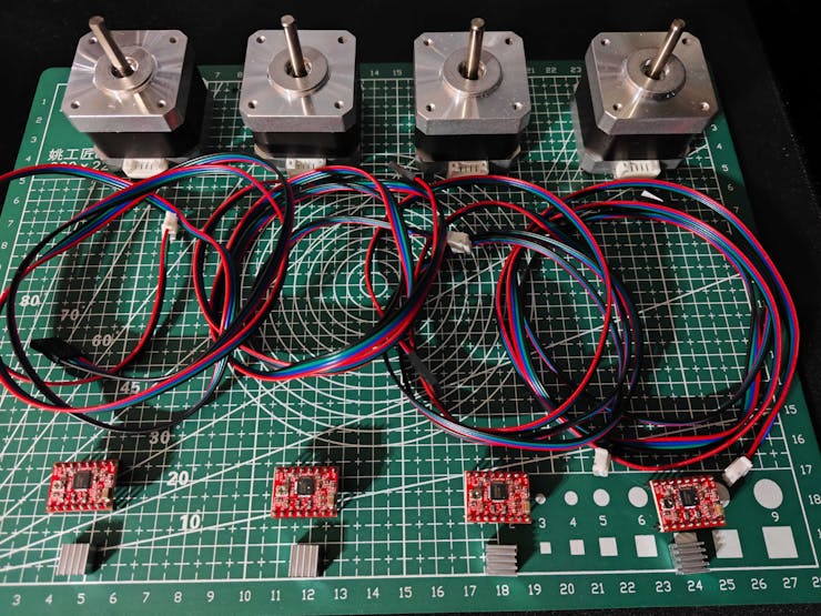
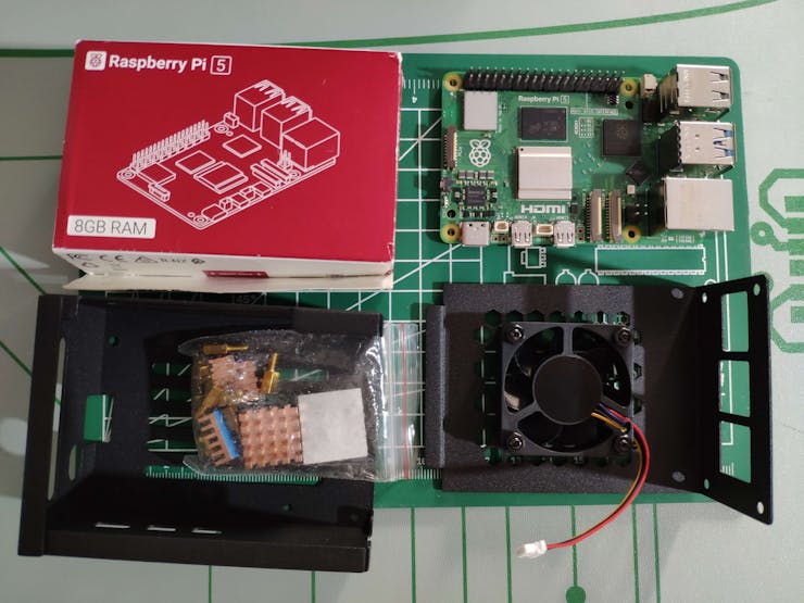
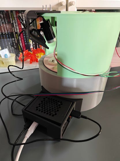
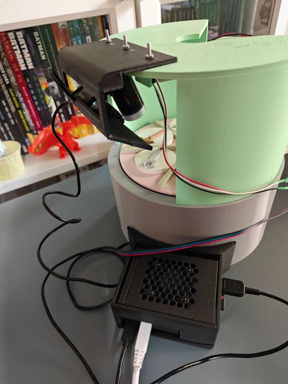
#️⃣ Furthermore, I put Raspberry Pi 5 into its aluminum case providing a cooling fan to secure all cable connections.
Step 1.1: Designing the Wall-E-inspired PCB layout and silkscreen graphics
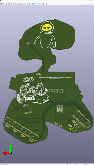
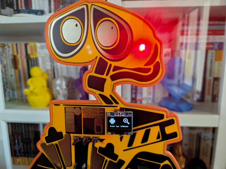
As I was prototyping the device structure and conceptualizing the workstation features, I pondered the question of how I should design a unique PCB for a smart shipping workstation. Then, I remembered the perennial efforts of Wall-E to move and arrange garbage as small packages. Thus, I drew my inspiration from Wall-E while designing this PCB, running an automated package-moving operation :)
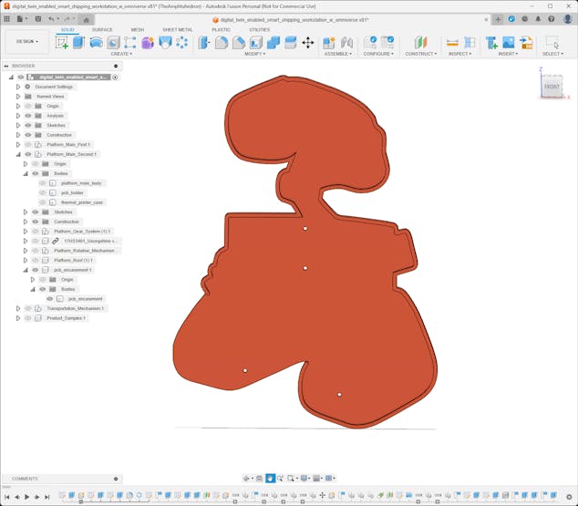
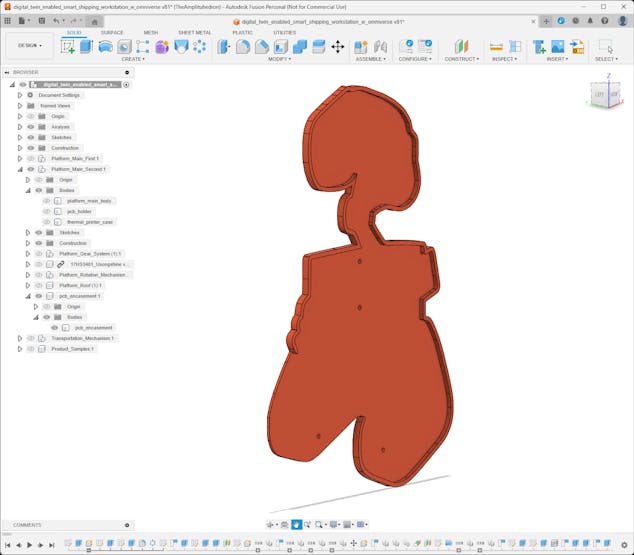
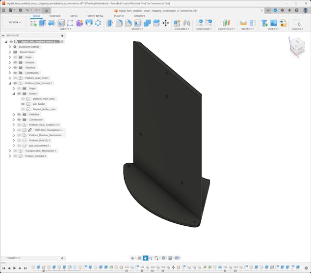
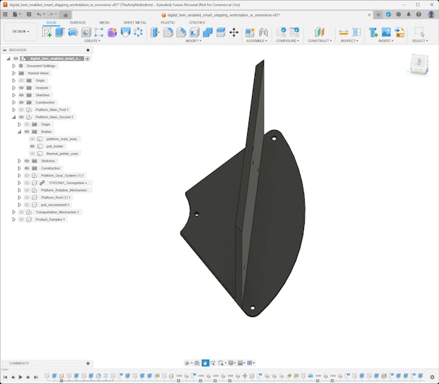
To simplify the PCB integration and place electronic components precisely while designing complementary 3D parts, I created the Wall-E PCB outline and a snug-fit PCB encasement on Autodesk Fusion 360.
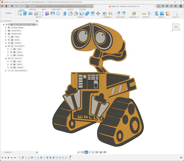
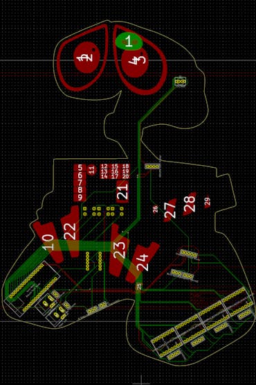
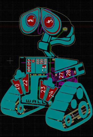
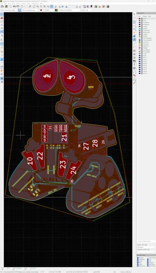
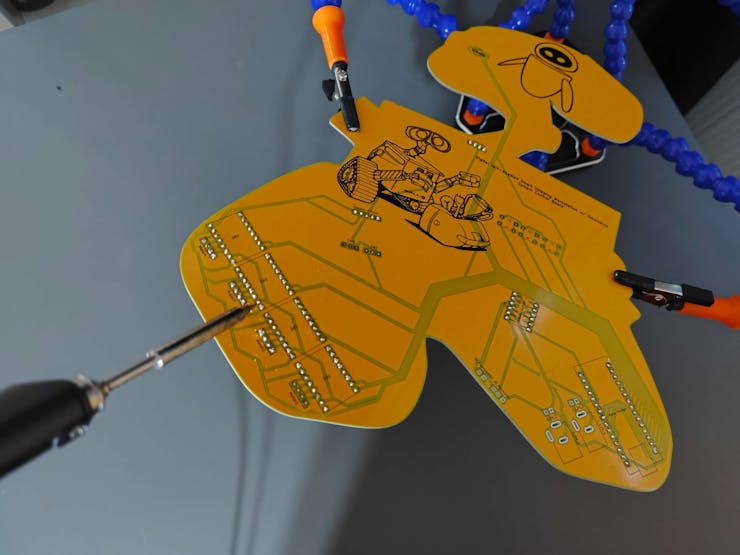
Then, I imported my outline graphic to Kicad 8.0 in the DXF format and designed the Wall-E PCB layout and silkscreen graphics according to the prototype electronic component connections.
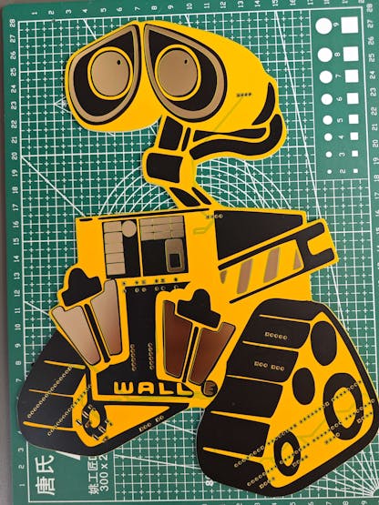
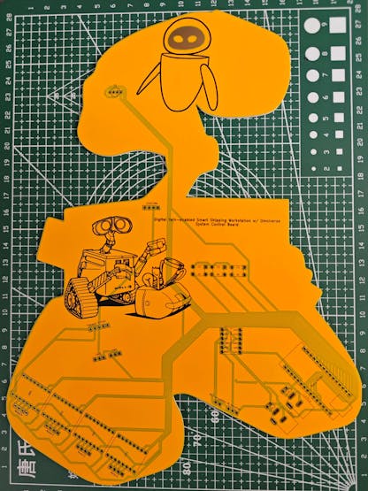
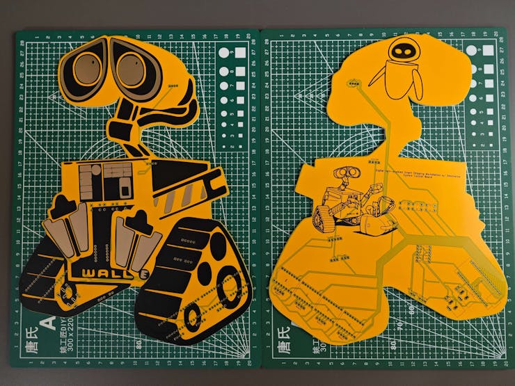
Step 1.2: Soldering and assembling the Wall-E PCB
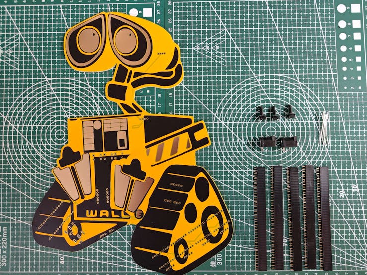
After completing the Wall-E PCB design, I utilized ELECROW's high-quality PCB manufacturing services. For further inspection, I provided the fabrication files of this PCB below, or you can order it directly from my ELECROW community page.
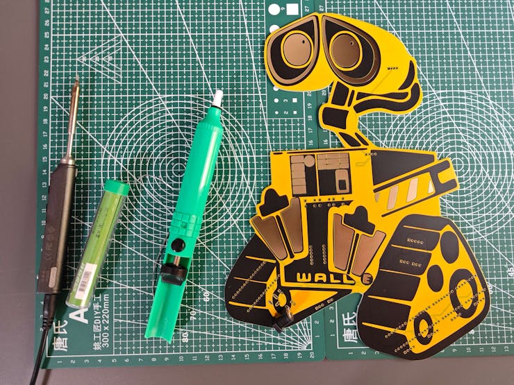
#️⃣ After receiving my PCBs, I attached all electronic components by utilizing a TS100 soldering iron and the soldering station.
📌 Component assignments on the Wall-E PCB:
A1 (Headers for Arduino Nano Matter)
DR1, DR2, DR3, DR4 (Headers for A4988 Stepper Motor Driver)
Motor1, Motor2, Motor3, Motor4, (Headers for Nema 17 [17HS3401] Stepper Motor)
SSD1306 (Headers for SSD1306 OLED Display)
Thermal1 (Headers for Embedded Thermal Printer)
L1 (Headers for Bi-Directional Logic Level Converter)
IR1 (IR Break-beam Sensor [Receiver])
IR2 (IR Break-beam Sensor [Transmitter])
SW1, SW2 (Micro Switch [KW10-Z5P])
C1, C2, C3 (6x6 Pushbutton)
D1 (5 mm Common Anode RGB LED)
J_5V_1, J_12V_1 (DC Barrel Female Power Jack)
J_5V_2, J_12V_2 (Headers for Power Supply)
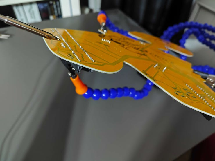
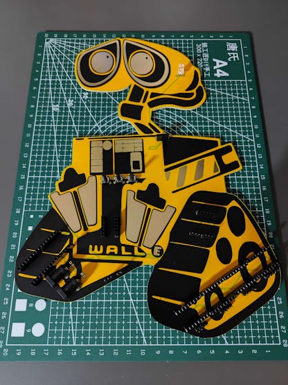
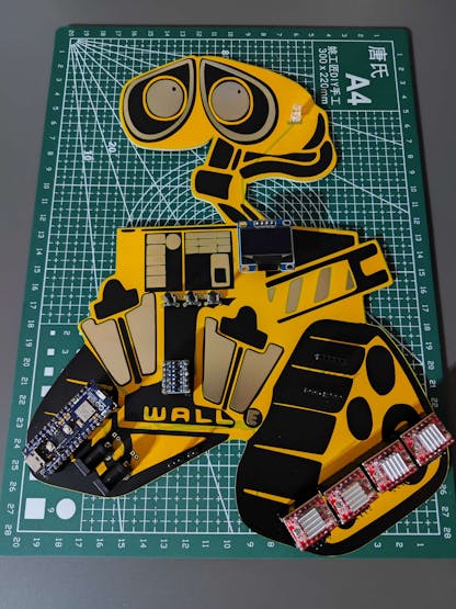
After concluding soldering components to the Wall-E PCB, I tested whether the PCB worked as expected or was susceptible to electrical issues; I did not encounter any problems.

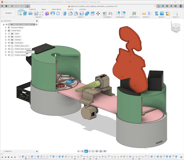
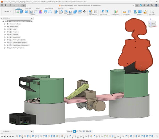
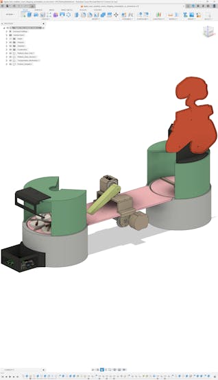
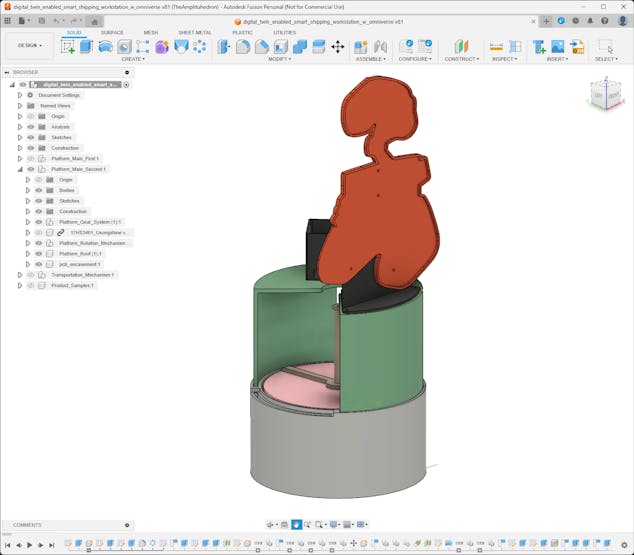
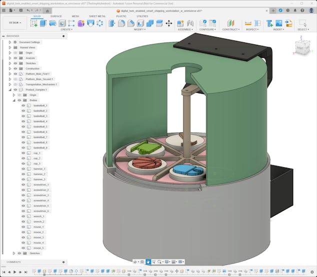
Step 2: Creating a fully functional virtual shipping workstation
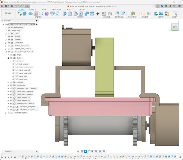
Even though I decided to build a virtual shipping workstation to present my reverse digital twin approach as a proof-of-concept project, I focused on designing an intricate mechanism manifesting an industrial-level shipping operation providing a professional product transportation system and a custom warehouse management system.
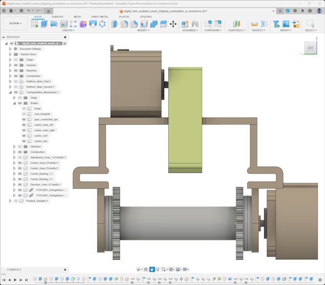
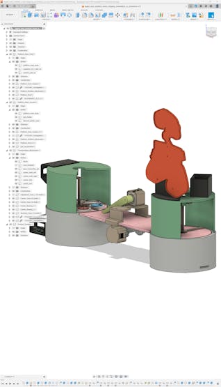
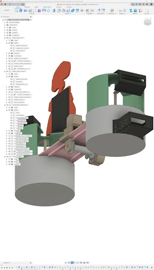
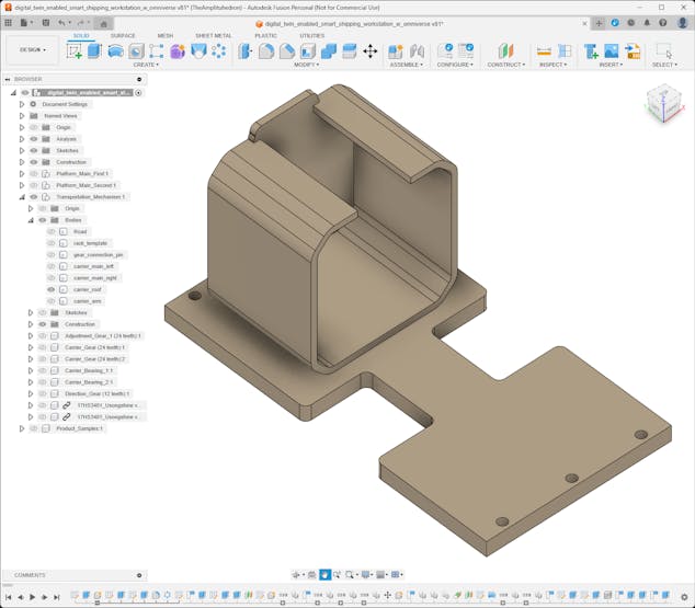
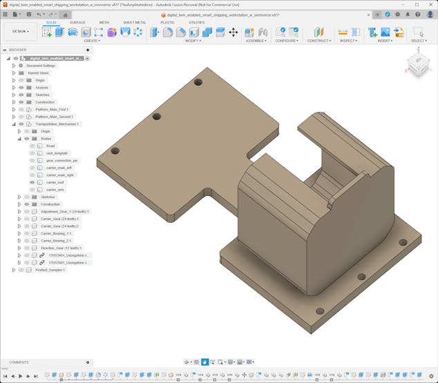
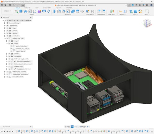
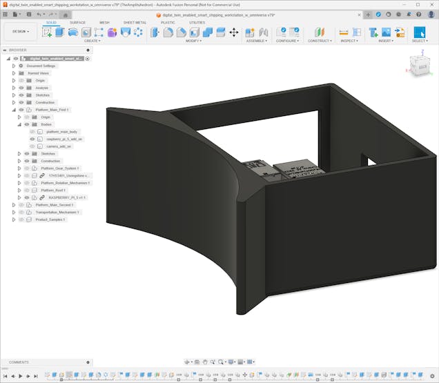
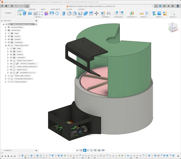
I designed all shipping workstation 3D parts on Autodesk Fusion 360, including custom mechanical parts for moving components.
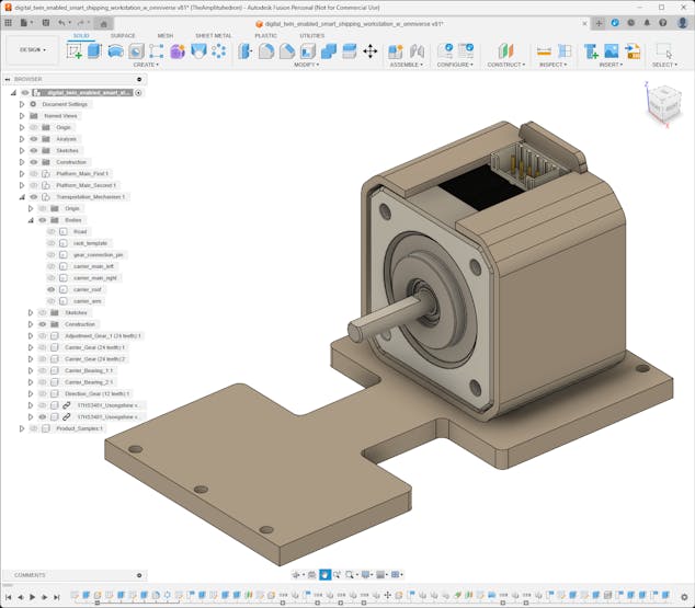
While designing 3D parts, I utilized some third-party CAD files to obtain accurate measurements and create a precise virtual construction.
Nema 17 (17HS3401) Stepper Motor | Inspect
Raspberry Pi 5 | Inspect
In the following steps, I will explain my design process for each 3D part categorically.
After finalizing all 3D parts, I exported the virtual shipping workstation as a single file in the OBJ format to produce an accurate virtual representation of the shipping workstation.


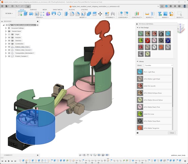
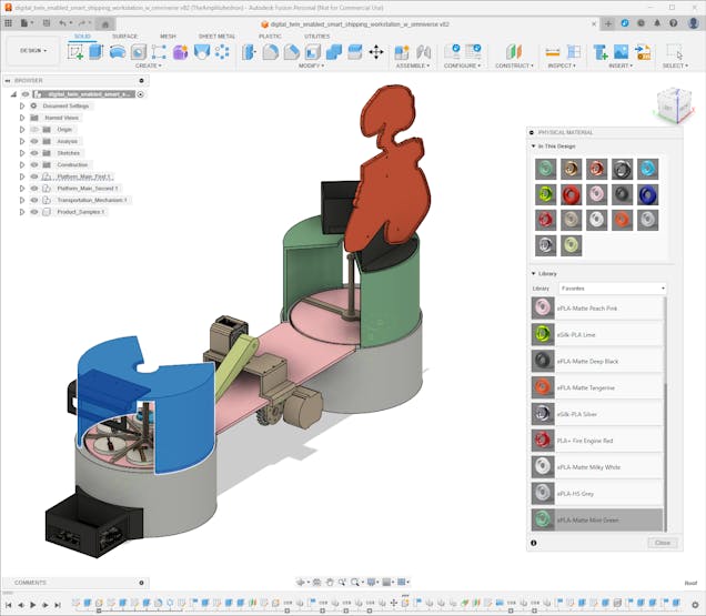
In accordance with my reverse digital twin approach, I had to envision each virtual shipping workstation 3D part appearance as close as possible to their real-world counterparts since I needed to construct a synthetic data set and train an object detection model even before printing these 3D parts. Therefore, while designing, I decided on the filaments I would utilize for each 3D part. Then, I searched for material type and color code for each filament to assign them to the corresponding 3D parts on Fusion 360.
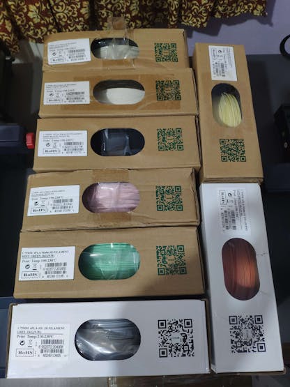
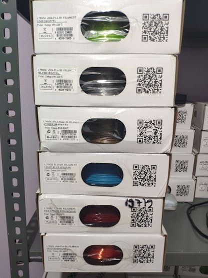
I selected these PLA filaments for different 3D parts.
🎨 For shipping workstation 3D parts:
- ePLA-HS Grey (#B5B8BE)
- ePLA-Matte Mint Green (#6DA582)
- ePLA-Matte Peach Pink (#F9C0CF)
- ePLA-Matte Deep Black (#2F3231)
- ePLA-Matte Milky White (#F7F5F4)
- ePLA-Matte Light Khaki (#AD9E8D)
- ePLA-Matte Tangerine (#E24C13)
- ePLA-Matte Almond Yellow (#C7D58C)
🎨 For sample product 3D parts:
- eSilk-PLA Lime (#9CE40C)
- eSilk-PLA Silver (#AAA3B5)
- eSilk-PLA Jacinth (#FF8472)
- ePLA-Metal Antique Brass (#CB9E70)
- PLA+ Light Blue (#37B8F5)
- PLA+ Fire Engine Red (#A62E34)
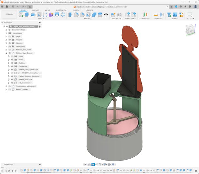
Step 2.1: Designing mechanical 3D components
Since I wanted to design the shipping workstation from the ground up, I decided to create custom mechanical components for the moving workstation parts.
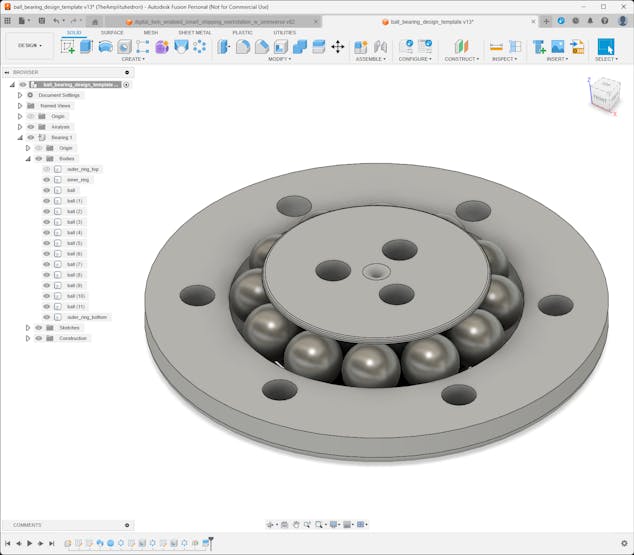
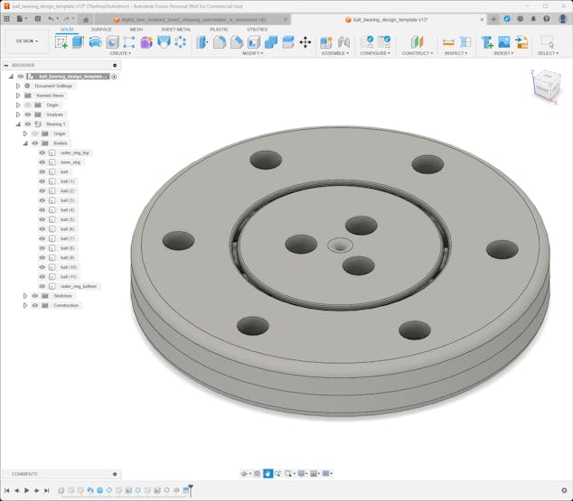
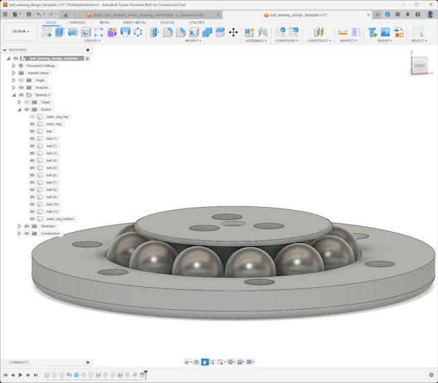
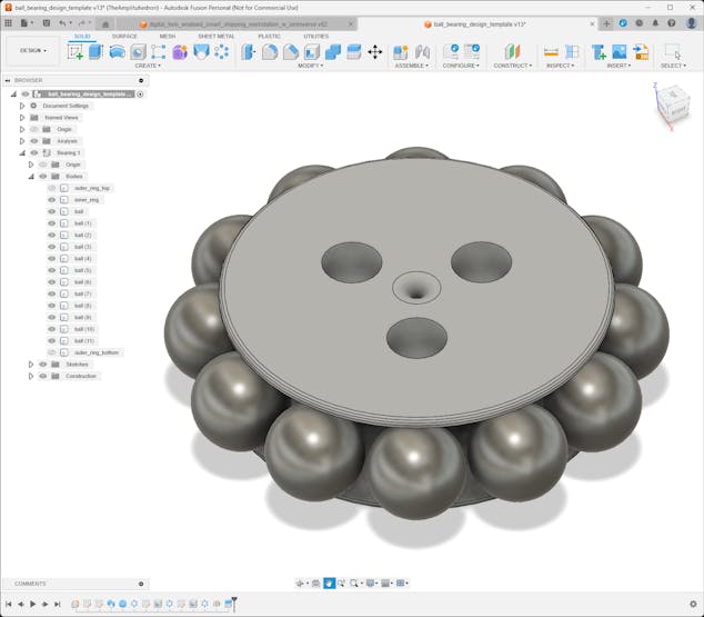
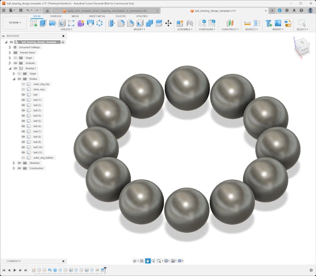
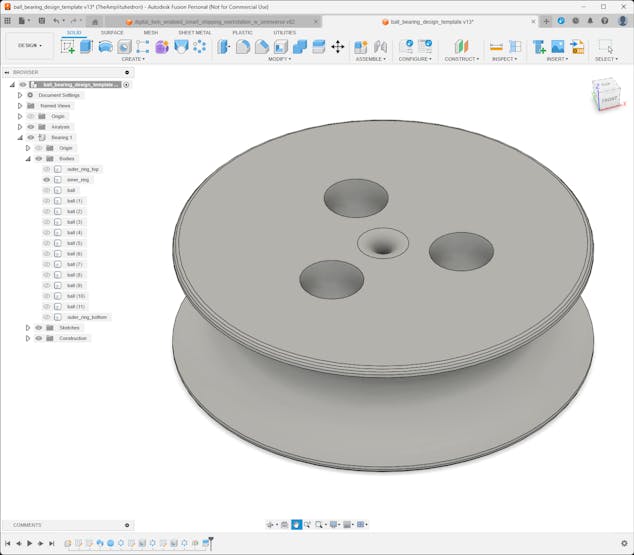
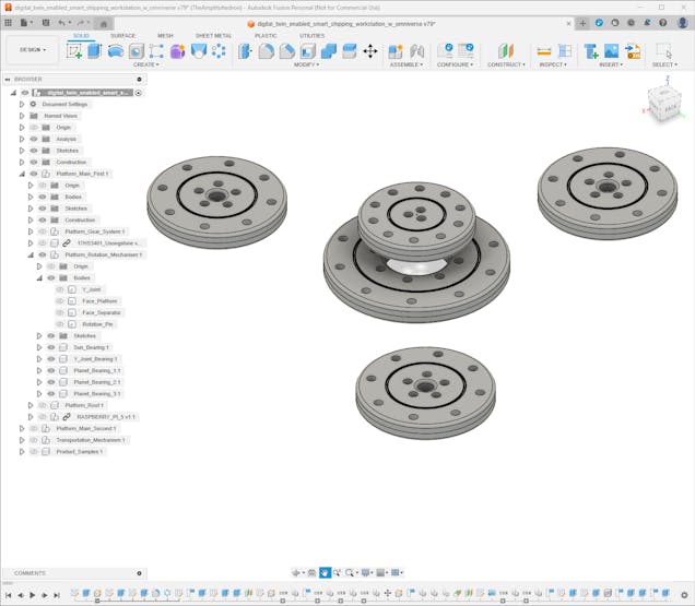
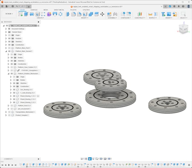
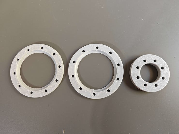
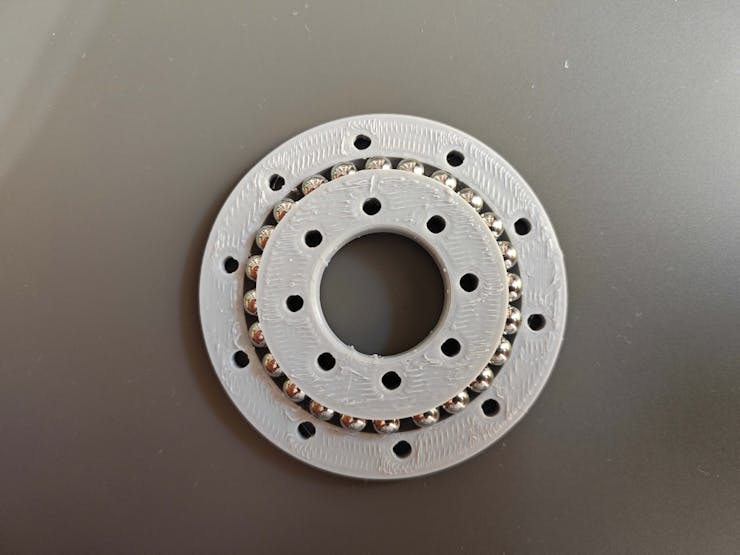
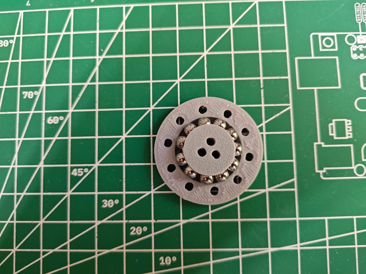
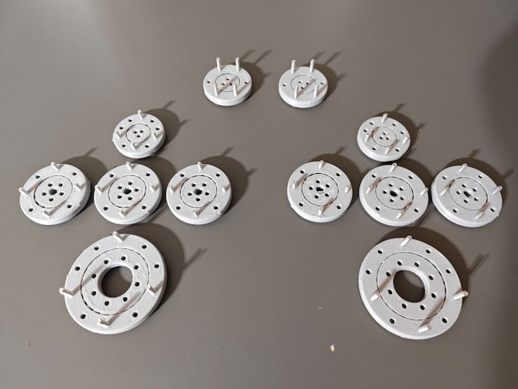
#️⃣ First, I started to work on designing a template for bearings optimized for 5 mm steel balls. In this regard, I was able to create ball bearings in different sizes to swivel mechanical components.
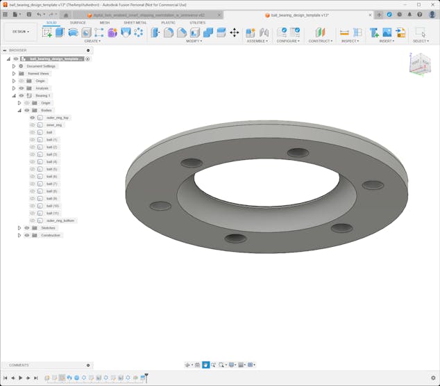
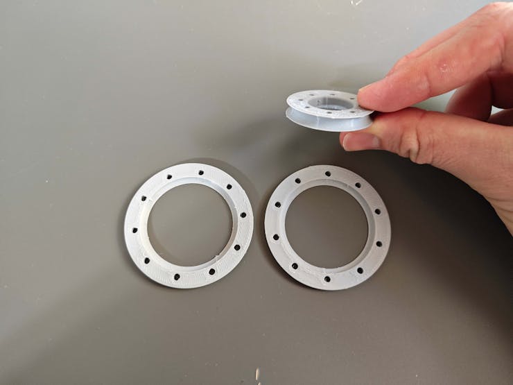
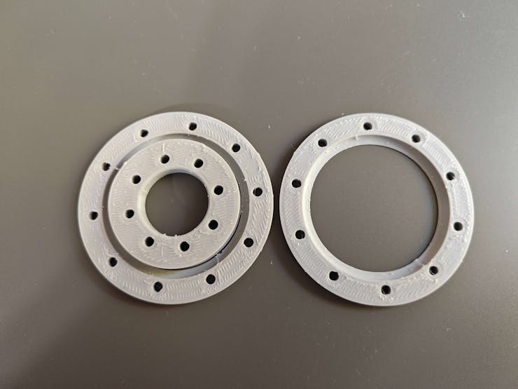
#️⃣ For a simple assembly process, I designed the bearing template in three parts: inner ring, top outer ring, and bottom outer ring. The outer ring (top and bottom) includes M3 screw holes to adjust the bearing tightness easily.
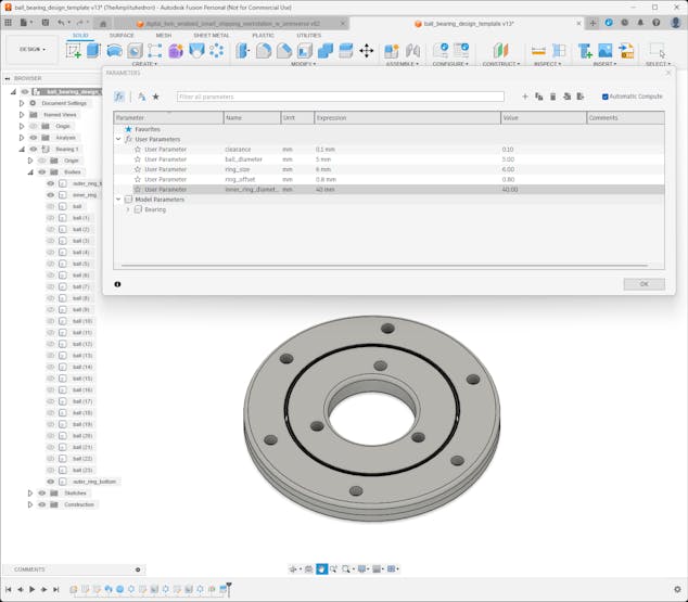
#️⃣ Since I used parameters to define the dimensions and clearances of the bearing template, I was able to create custom bearings in different sizes effortlessly.

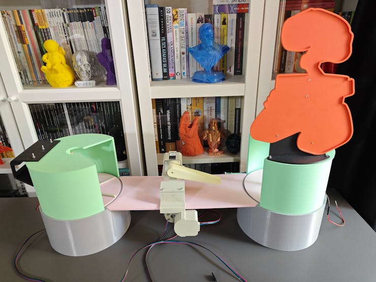
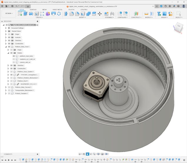
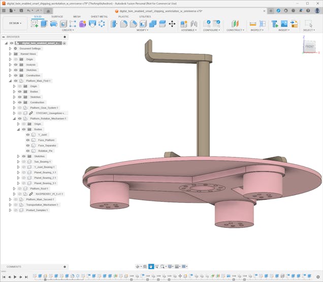
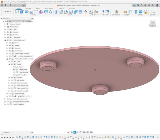
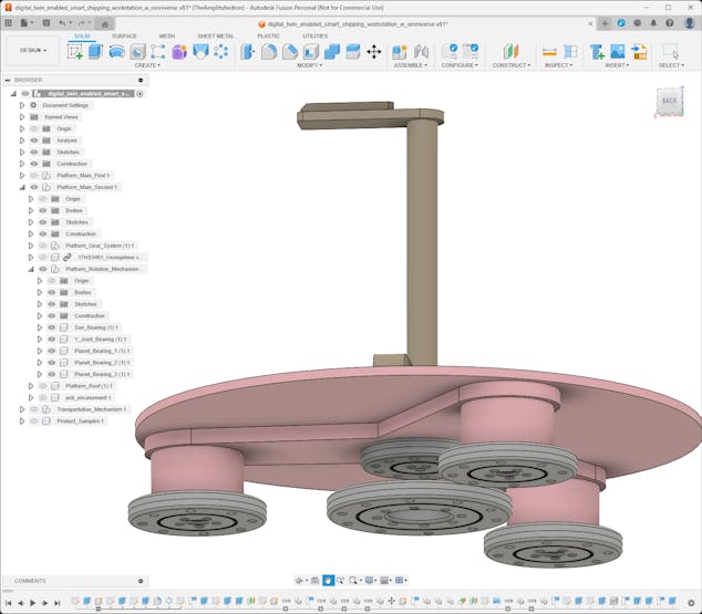
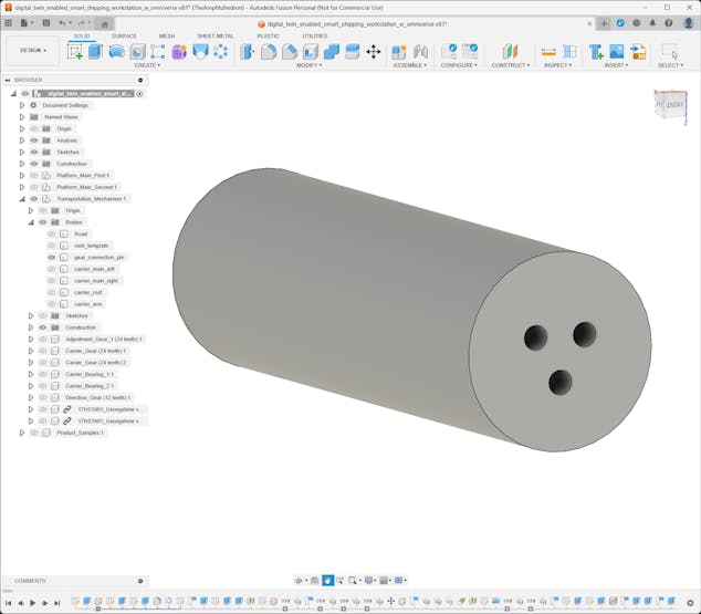
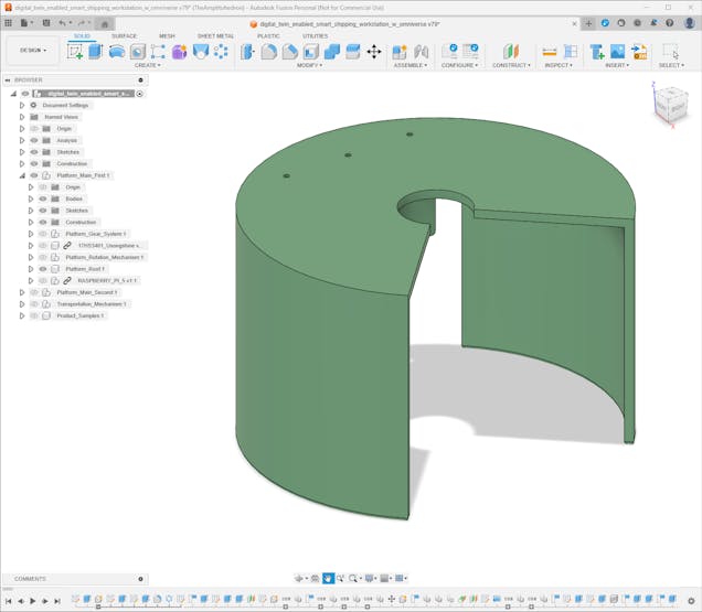
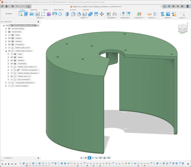
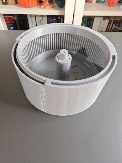
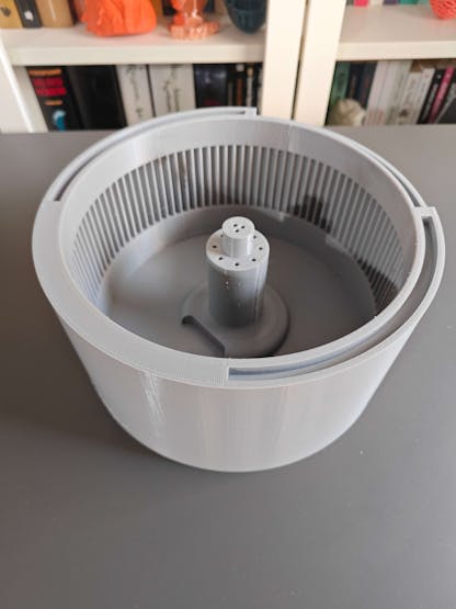
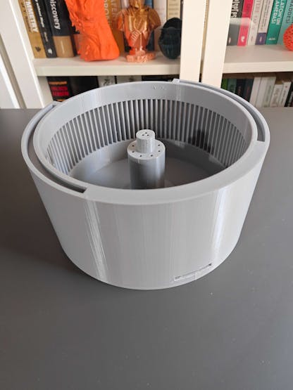
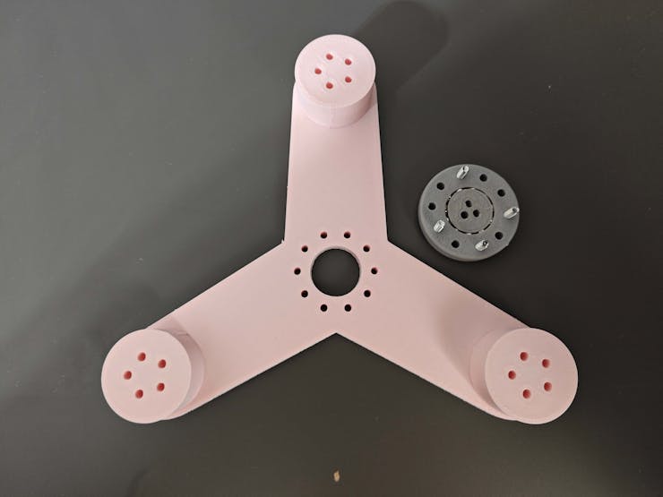
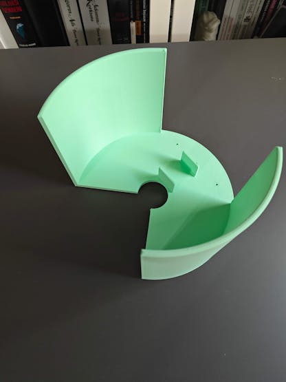
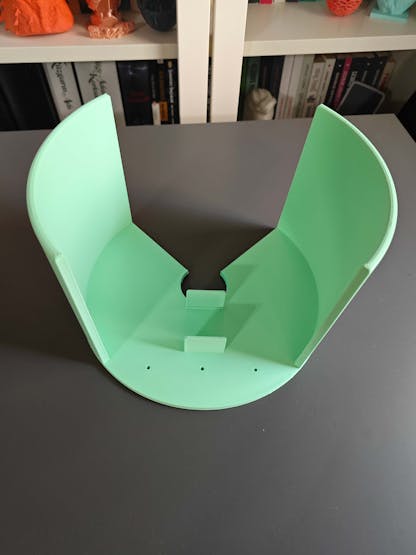
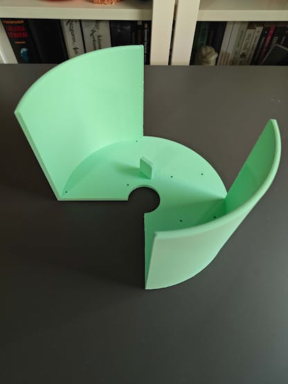
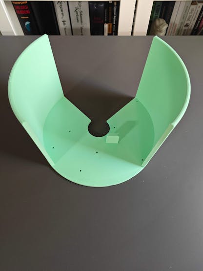
After completing the ball bearing template, I started to work on designing the two rotating platforms for storing and presenting sample products respectively.
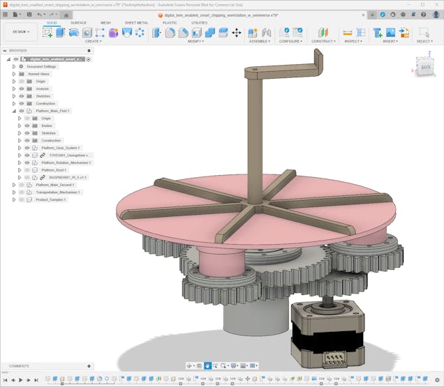
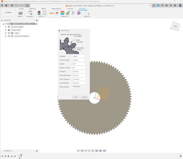
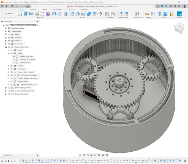
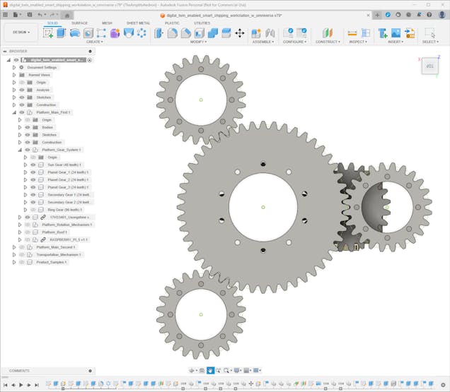
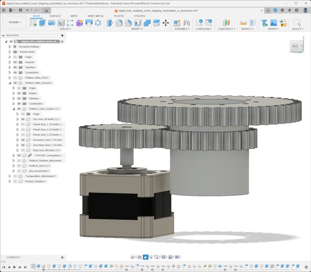
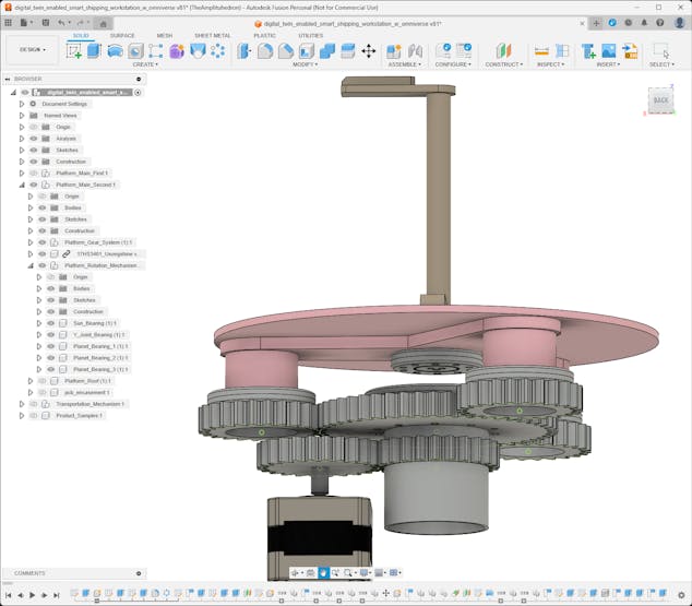
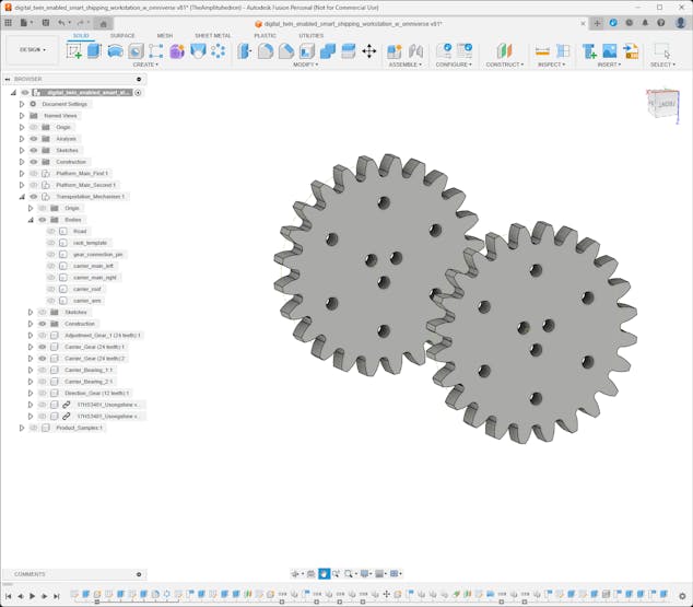
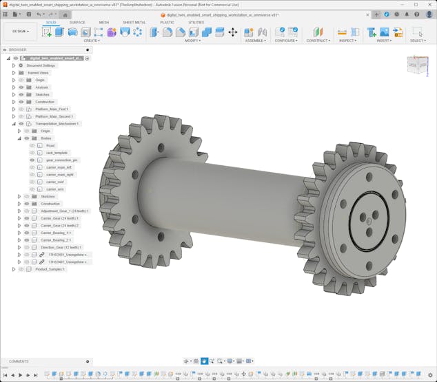
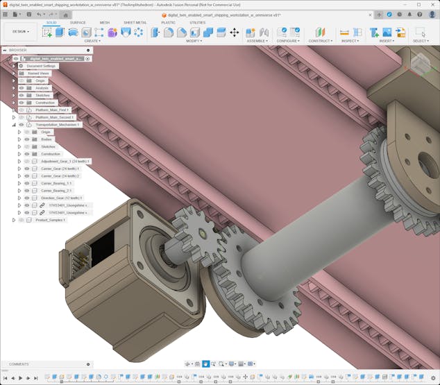
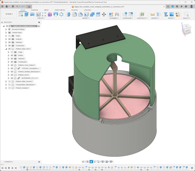
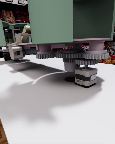
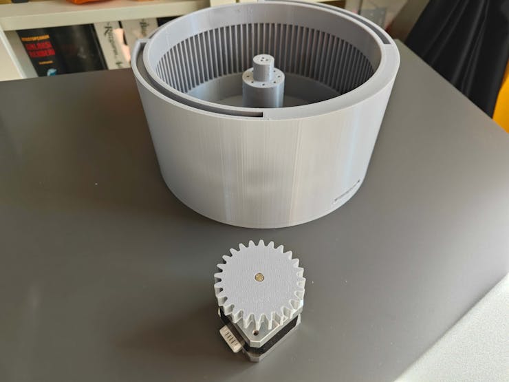
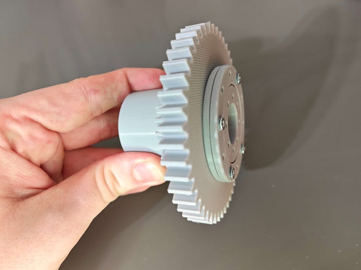
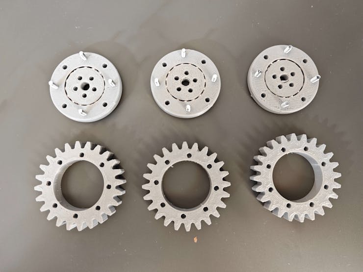
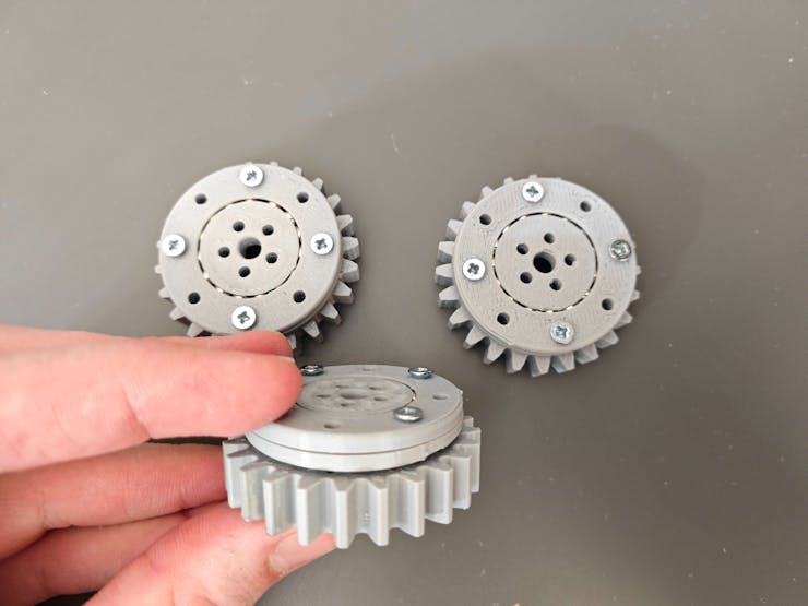
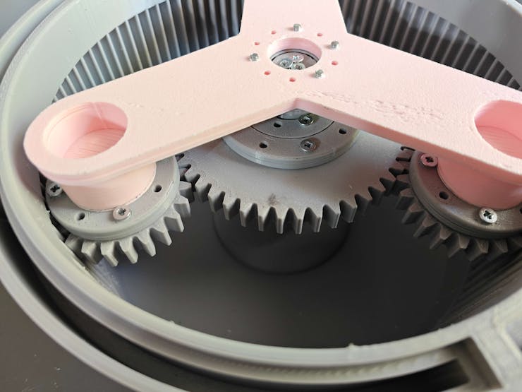
Since I wanted to create an industrial-level shipping workstation and showcase the digital twin capabilities for intricate mechanical components, I decided to design planetary gear mechanisms to rotate the platforms.
To generate gears in different sizes, I utilized the SpurGear add-in script.
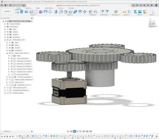
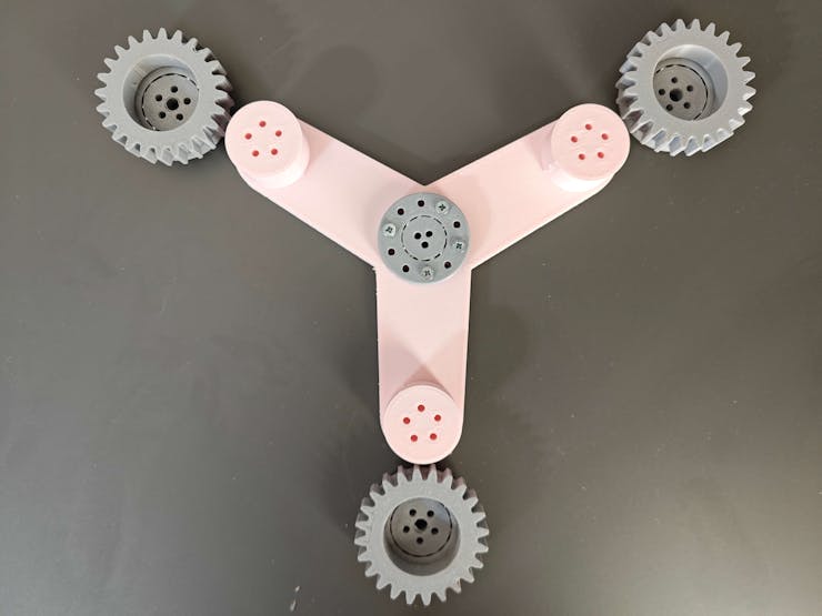
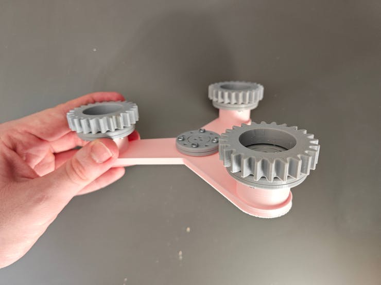
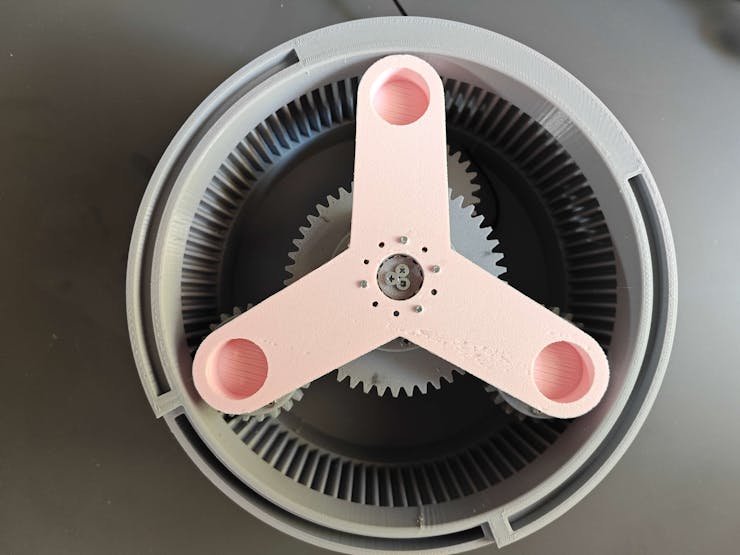
After experimenting with virtual planetary gear configurations, I decided to fix the ring gear and employ the planet carrier (Y-shaped) to attach and rotate the platform face. In this configuration, the sun gear behaves as the driver gear and provides higher torque while maintaining a lower speed.
To determine gear ratios and teeth numbers, I applied these equations:
🔢 Variables
- R ➡ Ring gear teeth number
- S ➡ Sun gear teeth number
- P ➡ Planet gear teeth number
- Tr ➡ Ring gear rotation
- Ts ➡ Sun gear rotation
- Ty ➡ Planet carrier (Y-shaped) rotation
🔢 Equations
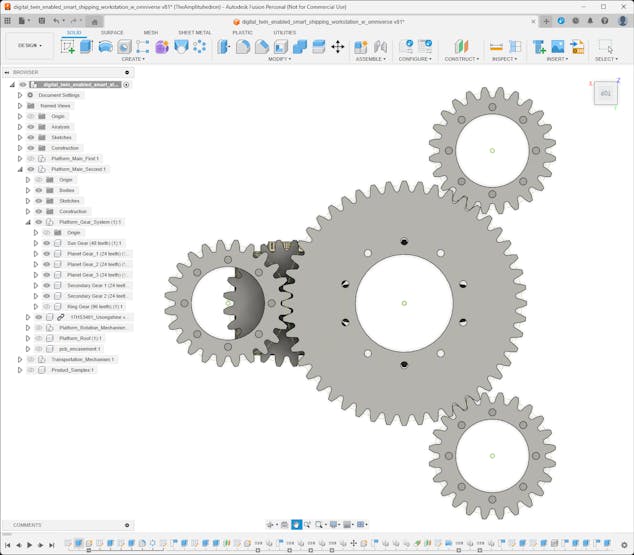
- R = (2 × P) + S
- (R + S) × Ty = (R × Tr) + (Ts × S)
🔢 Since the ring gear is fixed and I wanted to have a 1/3 gear ratio for Ty/Ts:
- (R + S) × Ty = Ts × S
- Ty = Ts × (S / (R + S))
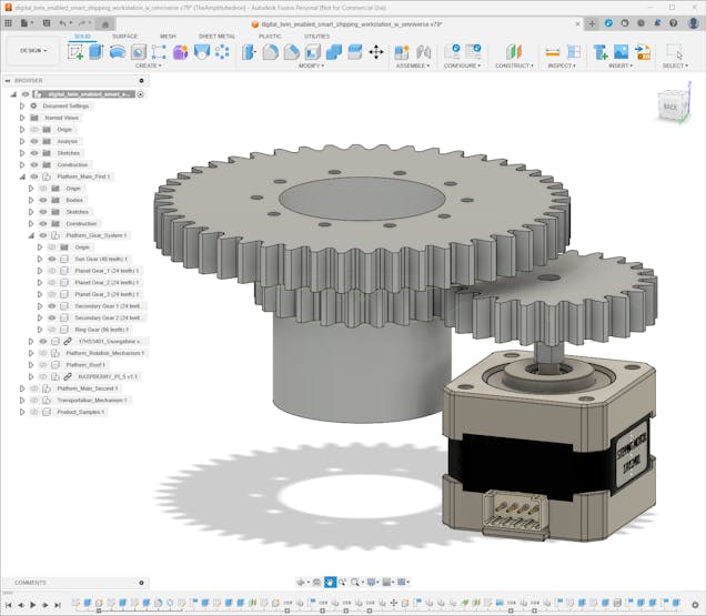
- R = 96
- S = 48
- P = 24
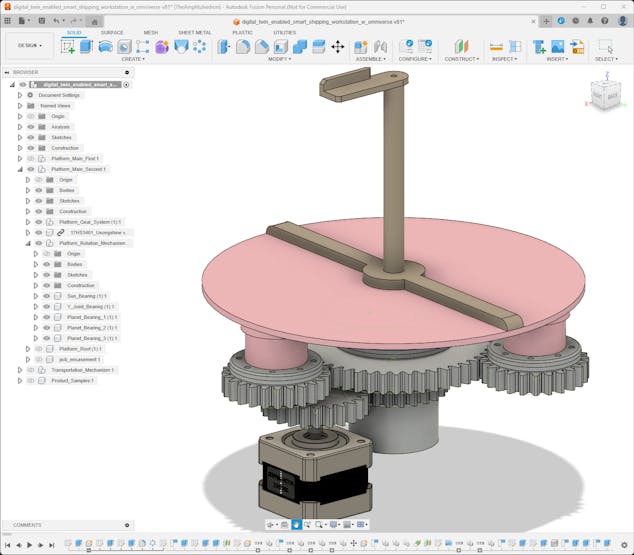
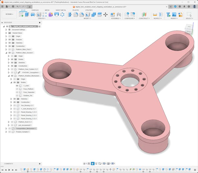
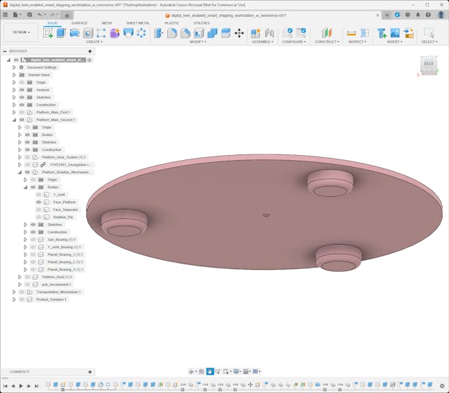
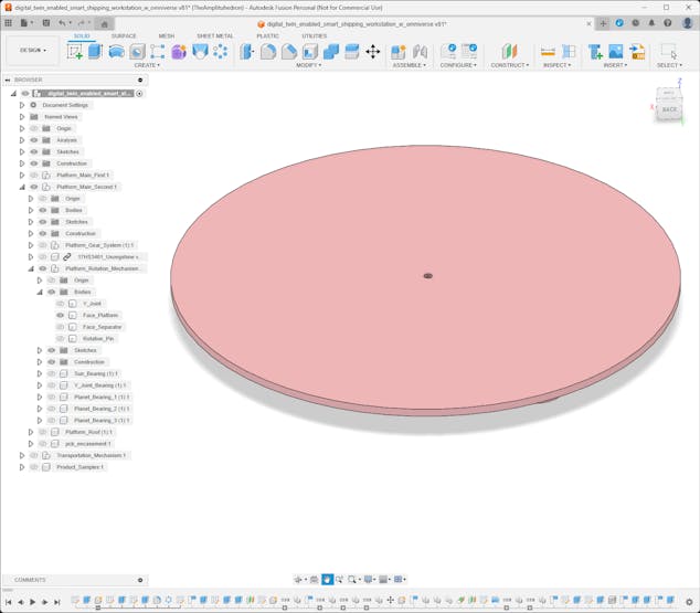
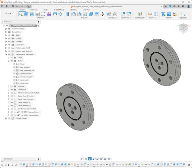
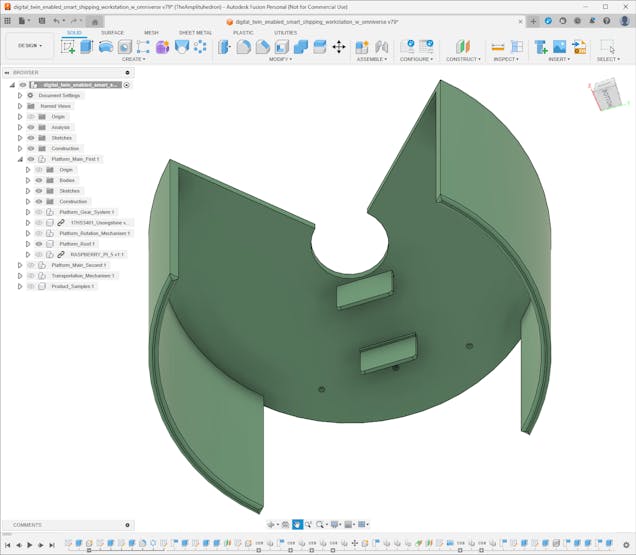
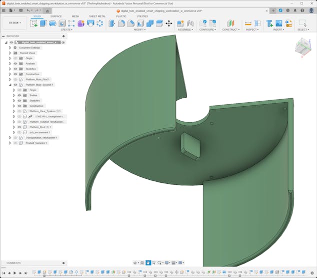
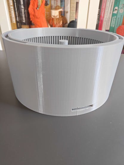
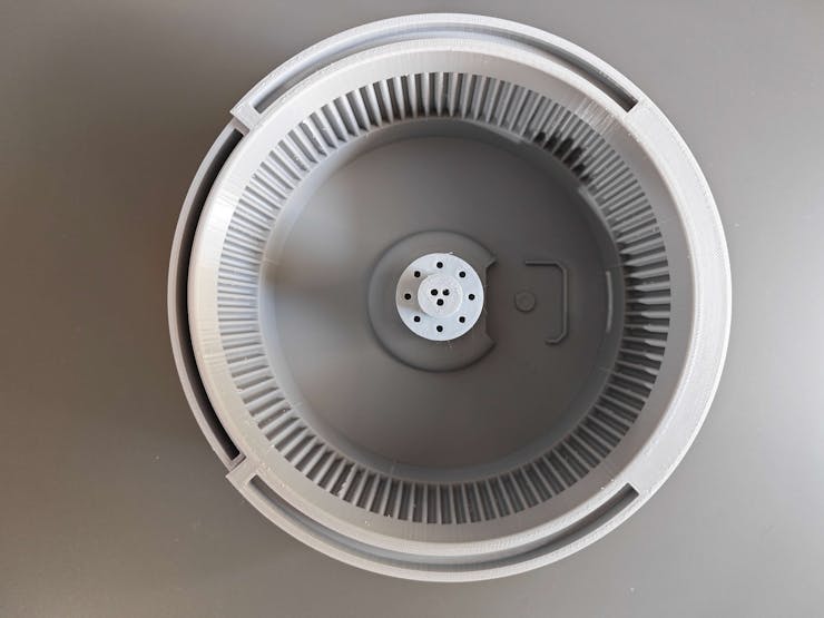
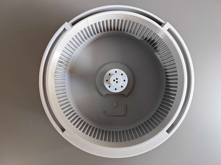
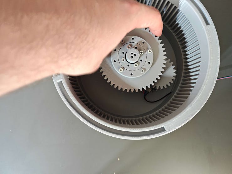
#️⃣ According to the fixed ring planetary gear configuration, I designed the platforms with the embedded ring gear.
⚙️ First platform:
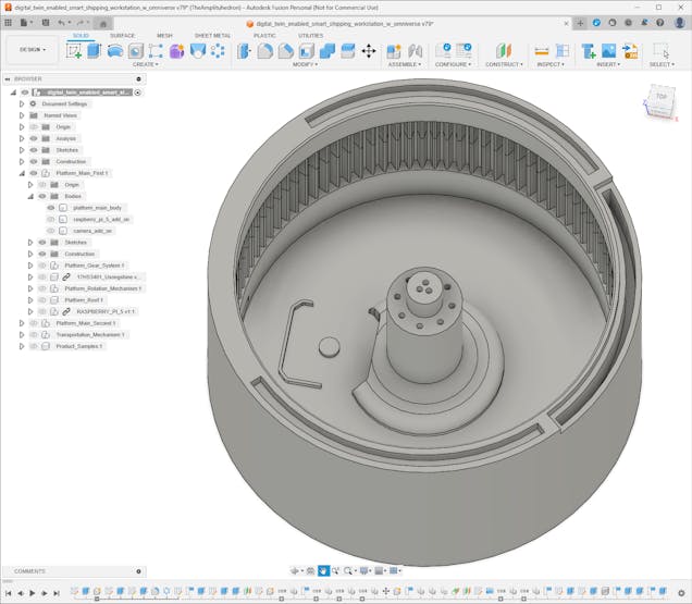
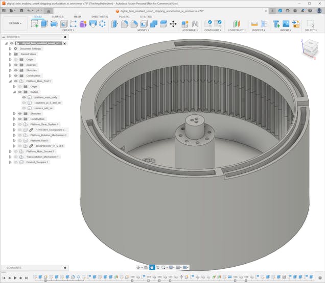
⚙️ Second platform:
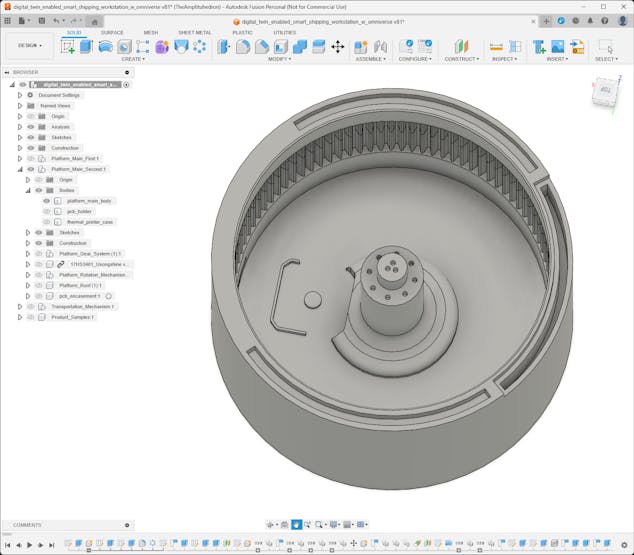
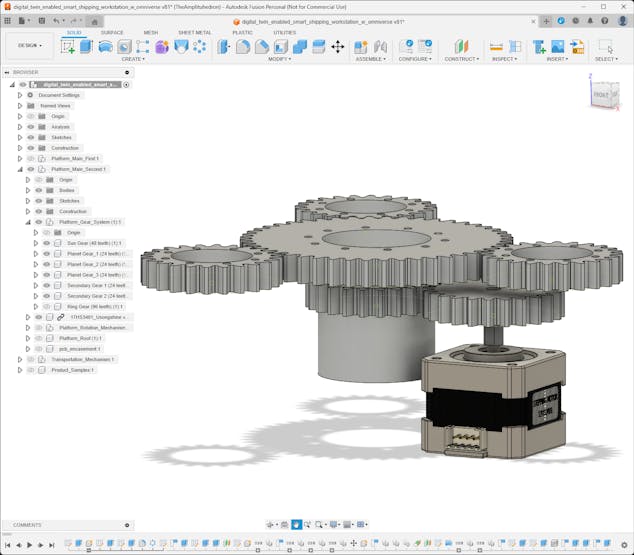
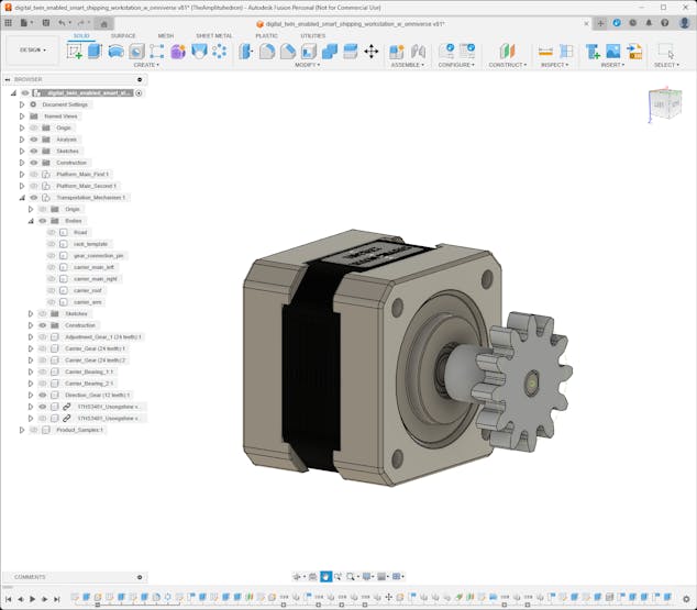
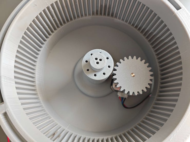
#️⃣ Then, I designed the planet gears, the sun gear, and the secondary stepper motor gear. In this regard, the Nema 17 stepper motor attached to the platform drives the secondary gear to rotate the sun gear which drives the planet gears.
⚙️ First platform:

⚙️ Second platform:
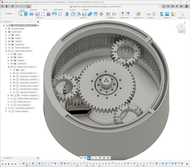
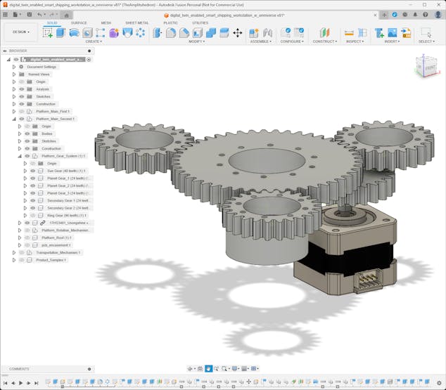
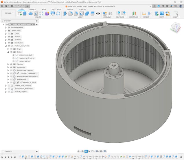
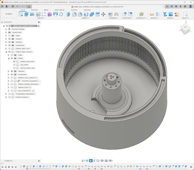
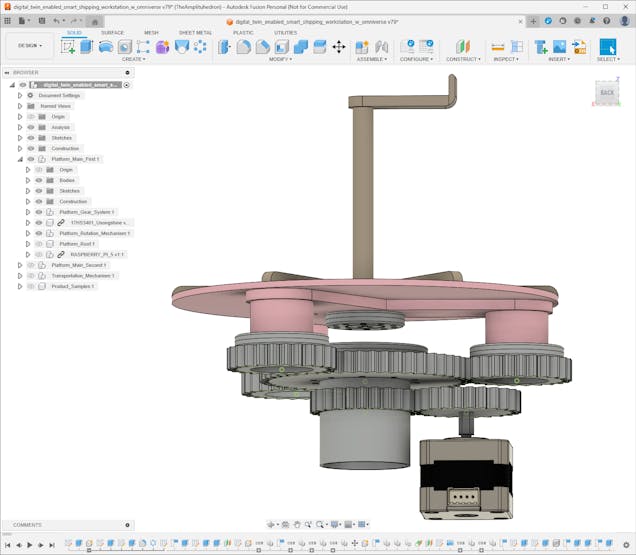
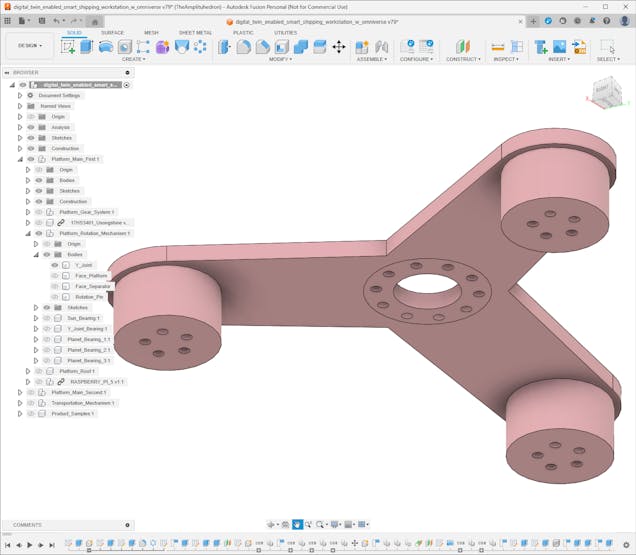
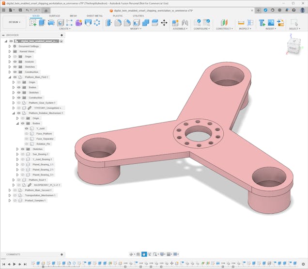
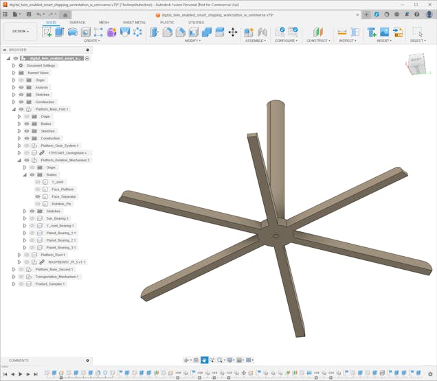
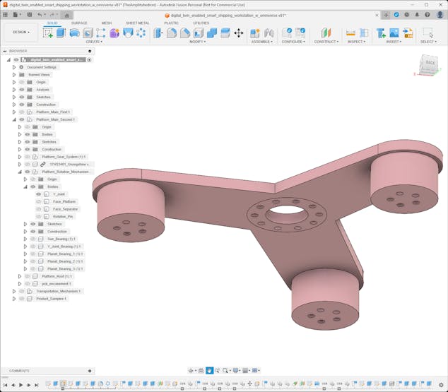
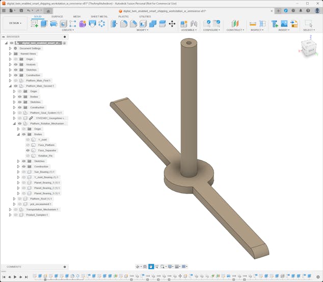
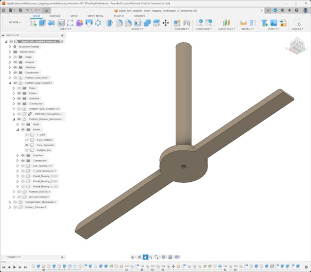
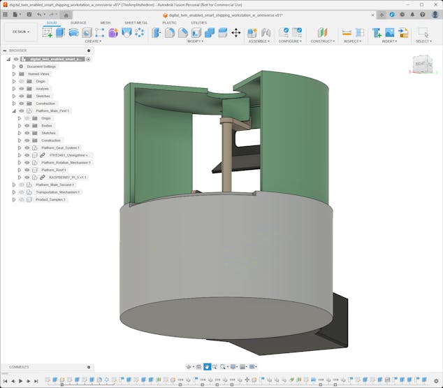
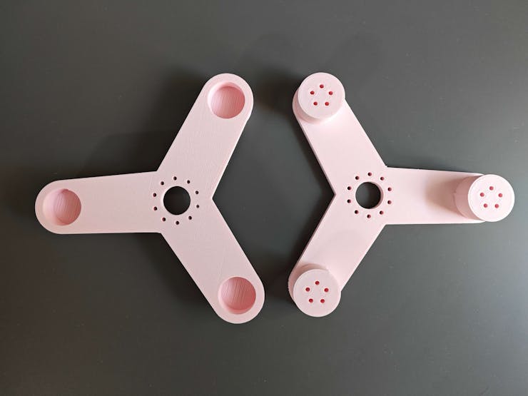
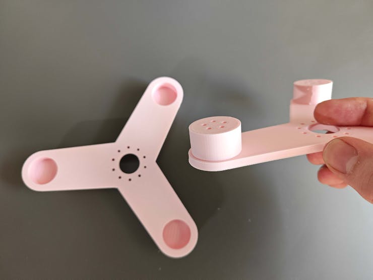
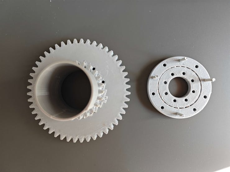
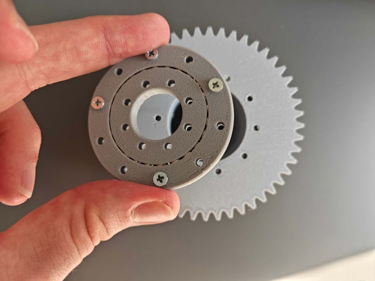
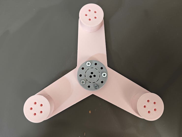
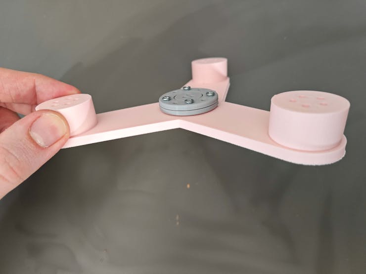
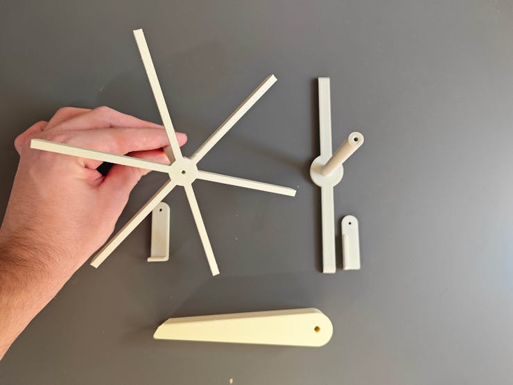
#️⃣ After completing the planetary gear mechanisms, I designed the Y-shaped planet carrier connected to the planet gears via custom bearings.
#️⃣ To stabilize torque distribution, the sun gear and the planet carrier are connected to the central shaft of the platform via custom bearings.
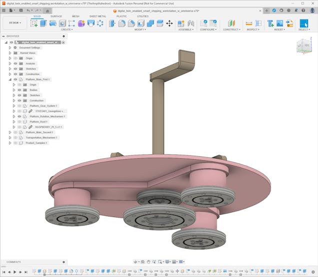
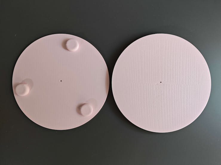
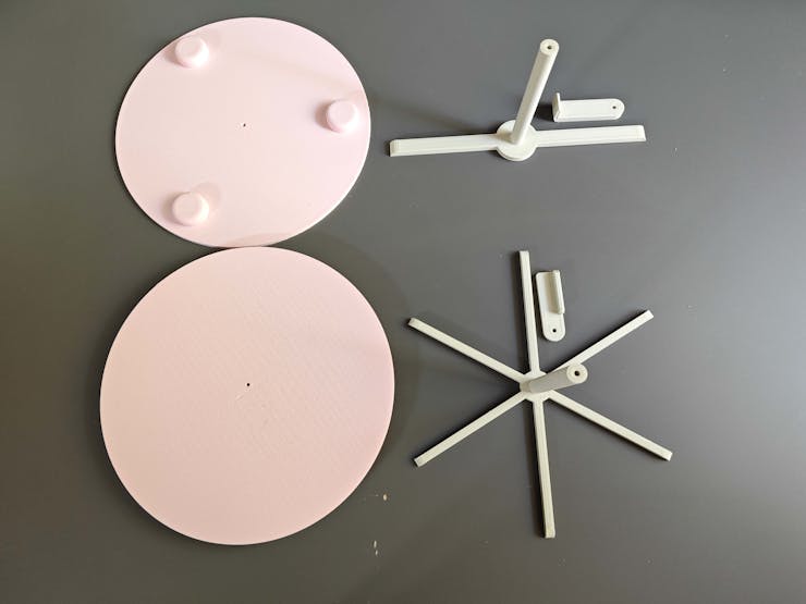
#️⃣ Then, I designed platform faces attached to the Y-shaped planet carriers via snap-fit joints.
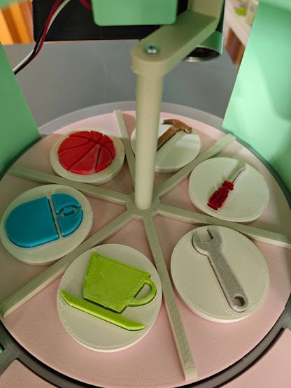
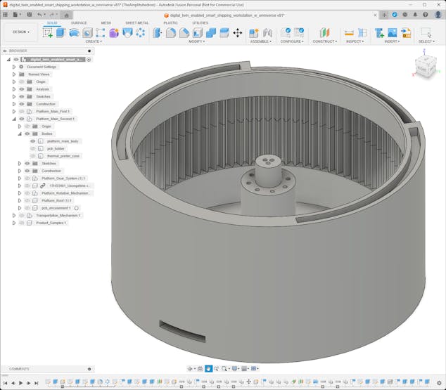
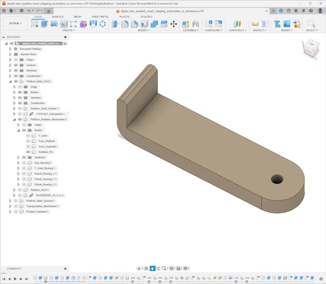
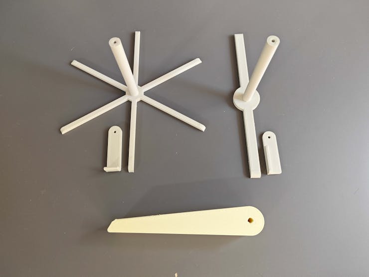
#️⃣ Since the first rotating platform stores sample products and the second rotating platform presents the transported product, I designed face separators and rotation pins accordingly.
#️⃣ The rotation pins are tailored for the selected platform homing methods — IR break-beam sensor and micro switch.
⚙️ First platform:


⚙️ Second platform:
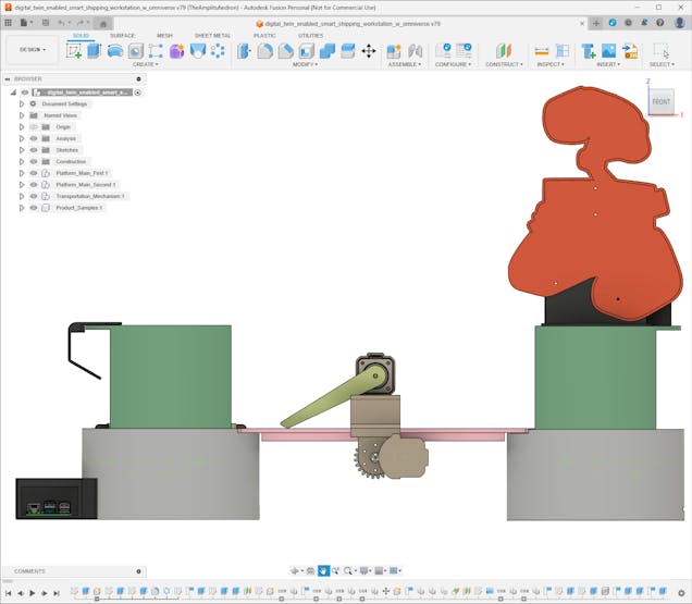
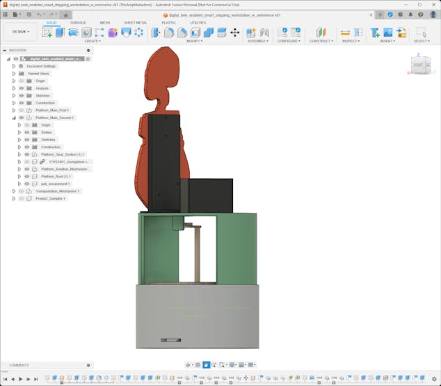
Step 2.2: Designing product transportation mechanism
After completing both rotating platform systems, I started to work on the industrial-level transportation mechanism to move the selected sample product from the first platform to the second platform.
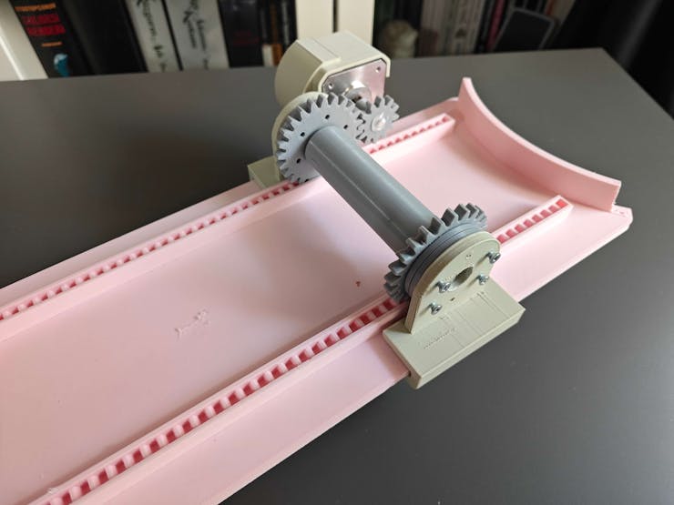
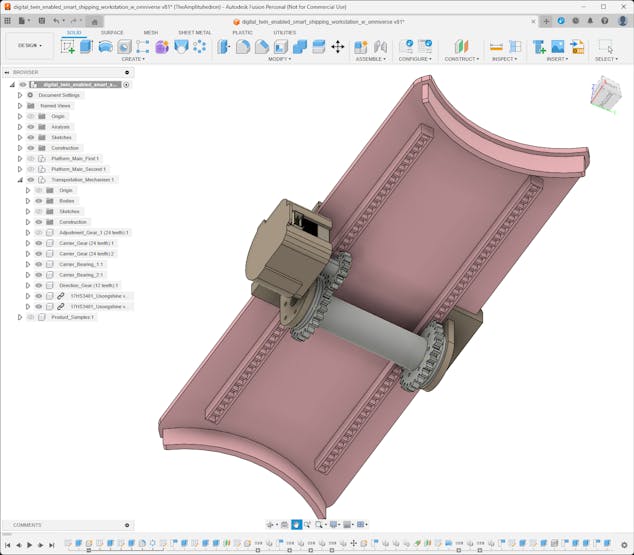
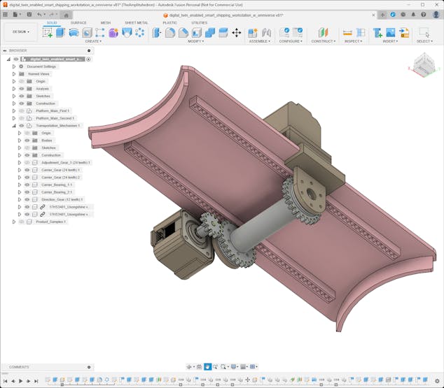
Conforming with my mechanical part design principle for the moving parts of the shipping workstation, I utilized gears to move the carrier on the transportation road. Nonetheless, since the product transportation mechanism requires linear motion, I designed a rack and pinion system converting rotational motion to linear motion.
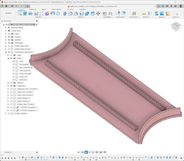
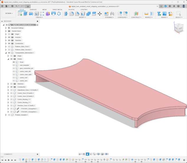
#️⃣ First, I designed the transportation road, bridging the first platform with the second platform. I integrated two linear gears (racks) at the bottom of the transportation road.

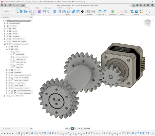
#️⃣ Then, I designed pinions, the pinion connection pin, and the stepper motor direction gear.
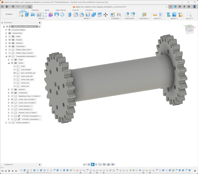

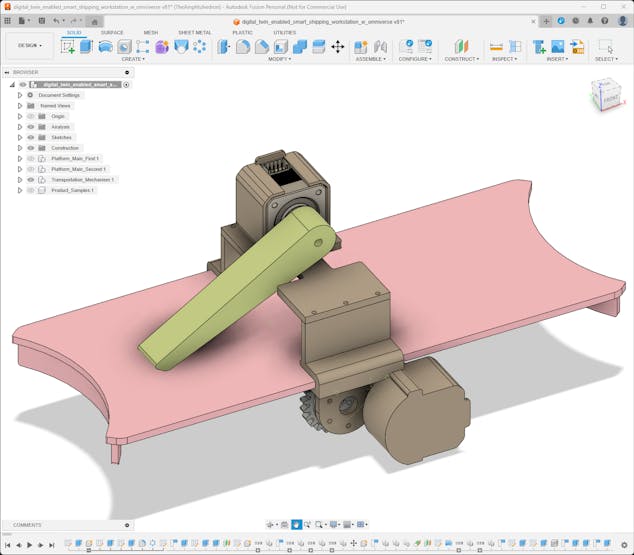
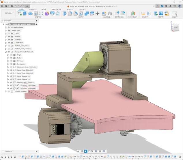
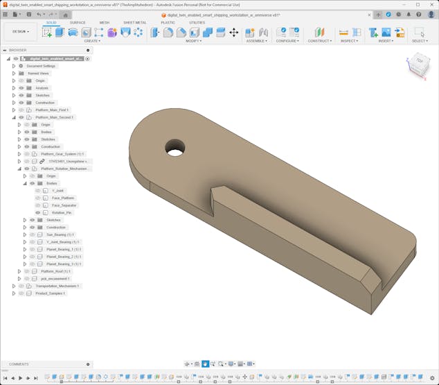
#️⃣ After completing the rack and pinion system, I designed the transportation carrier. I employed custom bearings to connect the carrier, pinions, and the pinion connection pin to enable linear motion while maintaining a stable torque distribution.
#️⃣ Then, I designed a basic carrier arm to hold the sample product still while pulling and pushing it on the transportation road.
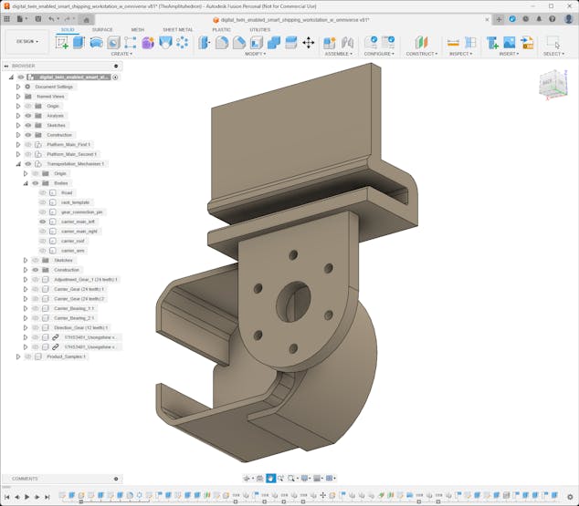
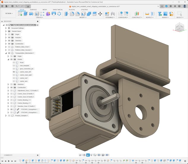
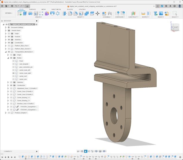
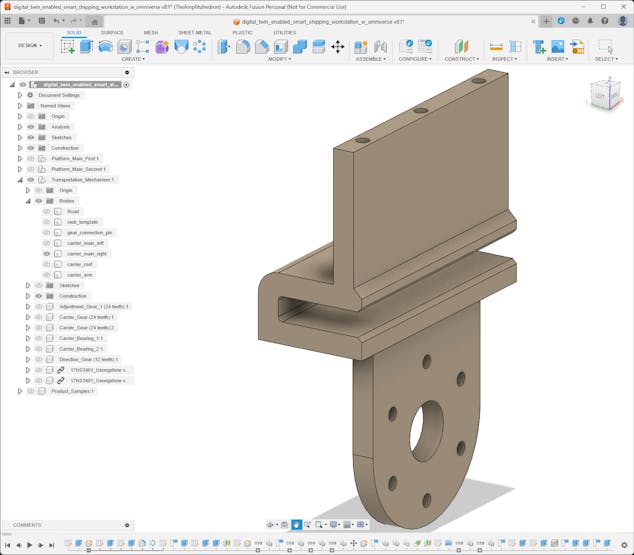
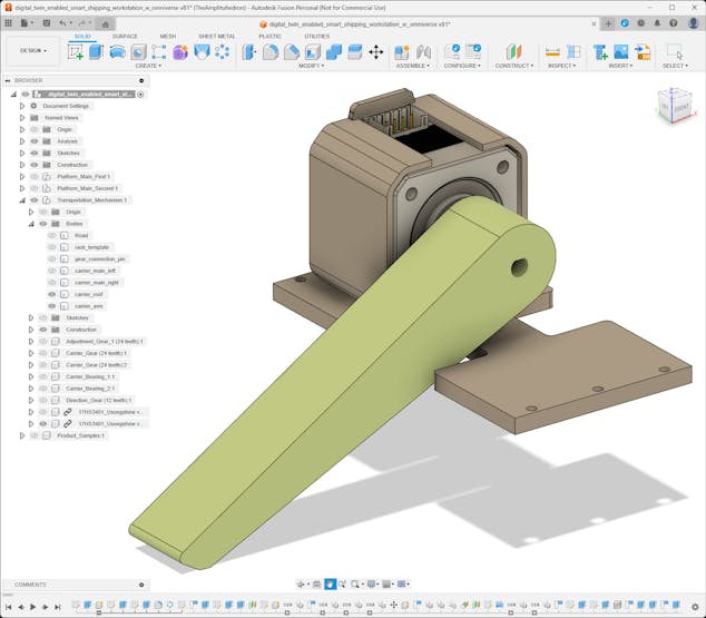
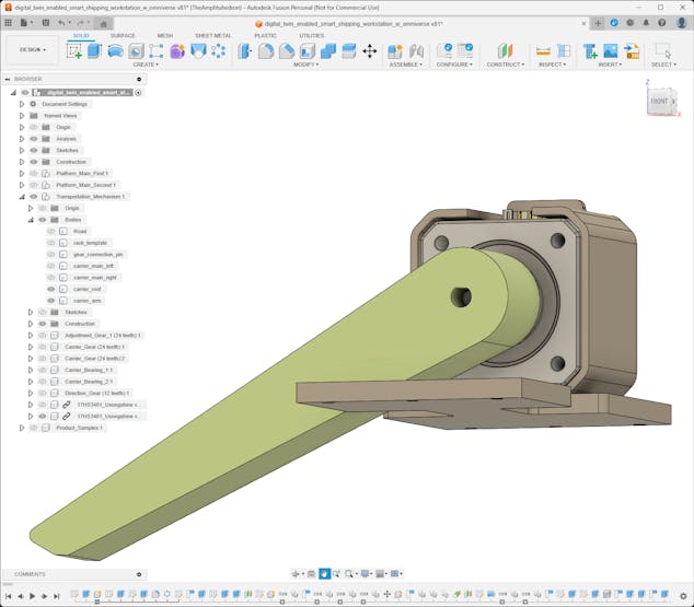
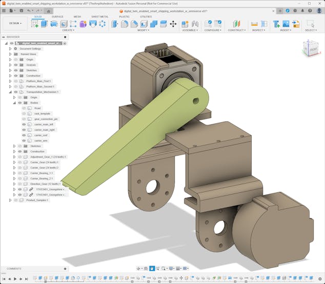
#️⃣ In this regard, the first Nema 17 stepper motor attached to the carrier drives pinions and the second one drives the carrier arm.


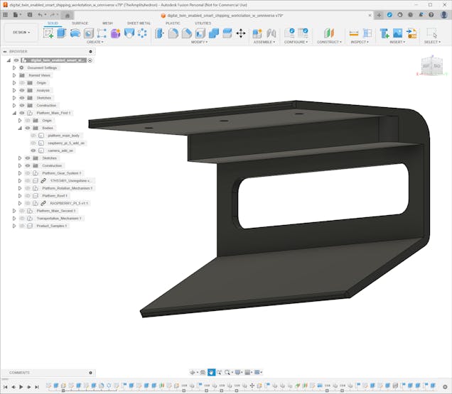
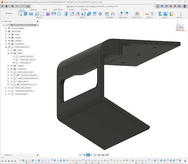
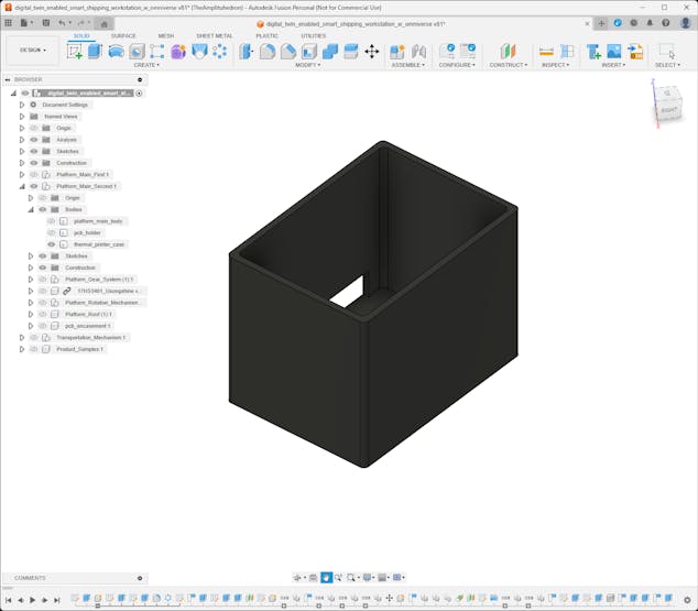
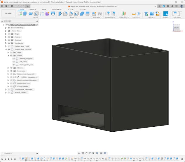
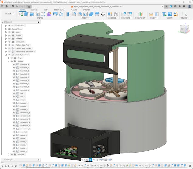
Step 2.3: Designing complementary accessories
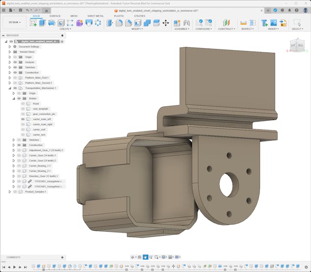
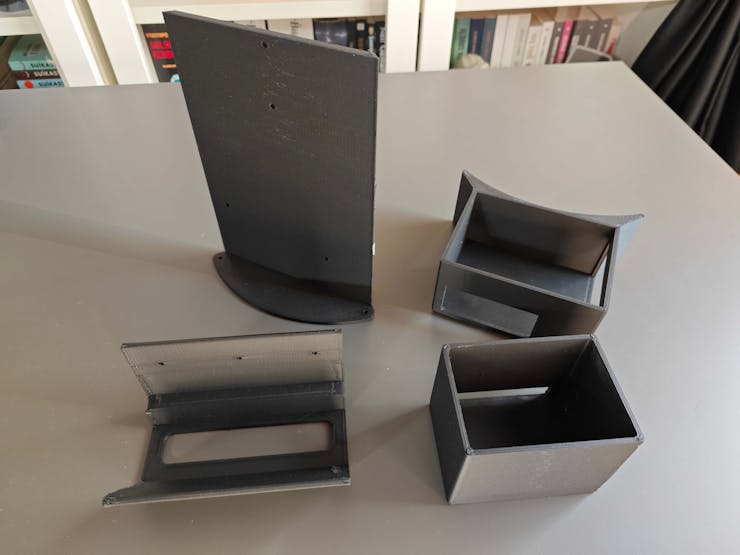
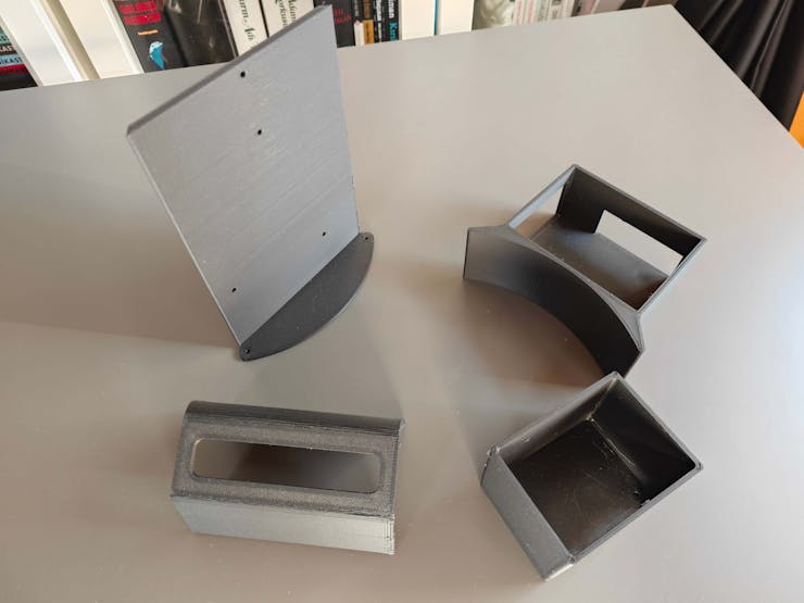
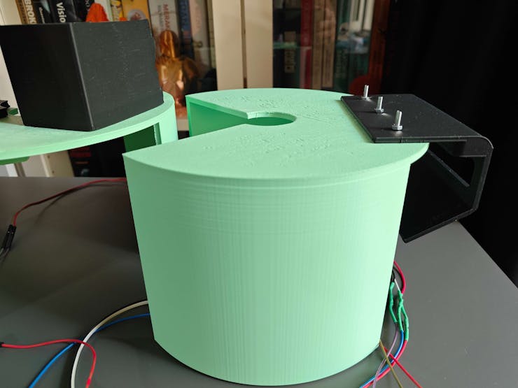
After completing mechanical 3D parts for the moving workstation components, I started to design complementary accessories, including the platform roofs, for the first and second platforms.
#️⃣ Since the first platform utilizes the IR break-beam sensor as the homing method to synchronize the 200-step per rotation pattern for 60° turns, I designed the first platform roof compatible with the IR sensor receiver and transmitter.
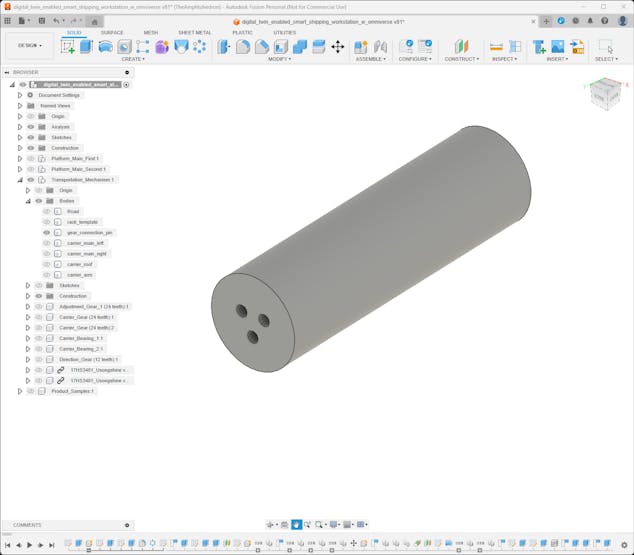
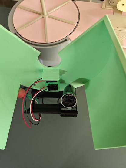
#️⃣ Then, I designed add-ons for Raspberry Pi 5 and a USB webcam since the first platform stores the sample products for automated selection and transportation process.
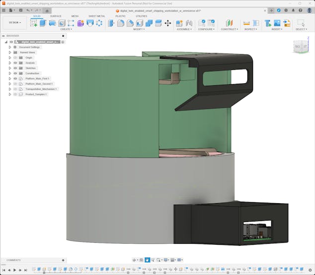
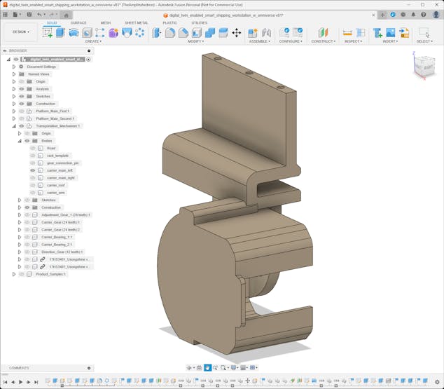
#️⃣ Since the second platform employs the micro switch as the homing method to align the face separator toward the transportation road, I designed the second platform roof compatible with the micro switch.
#️⃣ Then, I designed the add-on for the thermal printer and the mount for the PCB encasement since the second platform exhibits the selected and transported product.
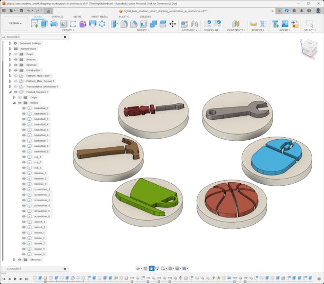
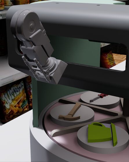
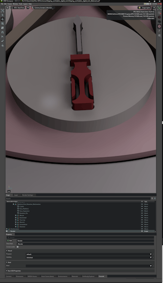
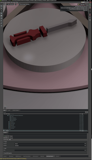
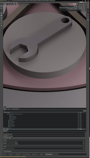
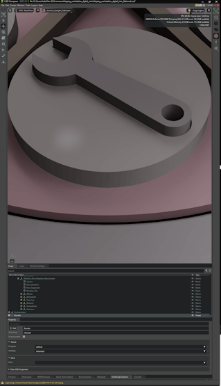
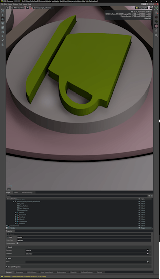
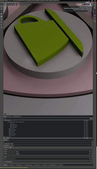
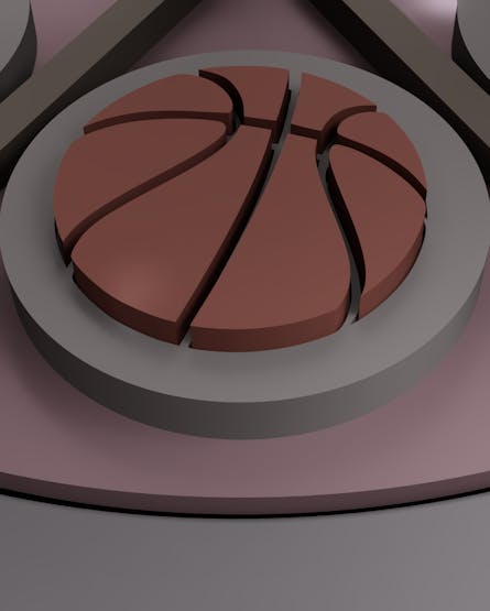
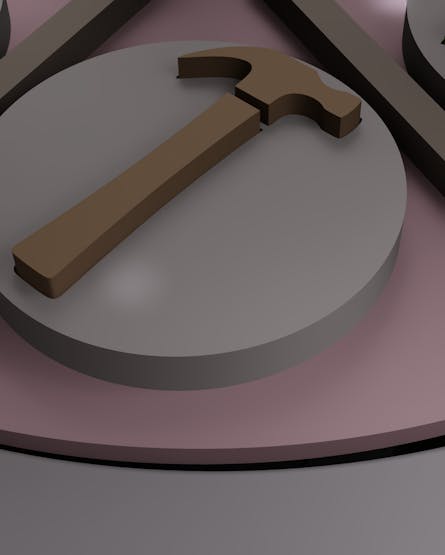
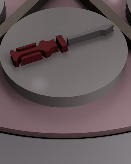
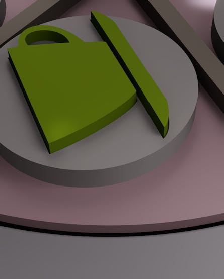
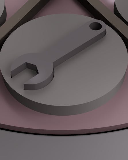
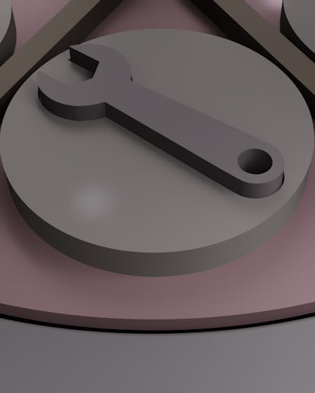
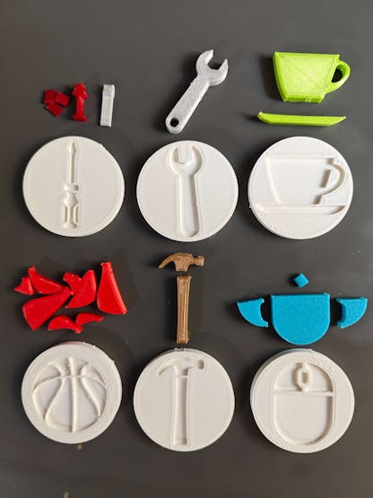
Step 2.4: Designing customized sample products
After completing the shipping workstation 3D parts, I focused on designing unique sample products since I wanted to examine the precision and efficiency of an object detection model trained on synthetic images of products that do not exist in the market.
In this regard, I was able to investigate whether it is feasible and cost-effective to initiate developing an AI-based solution for industrial operations with a synthetic data set generated from virtual product representations even before manufacturing or mass producing them.
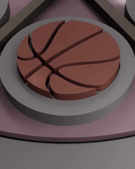
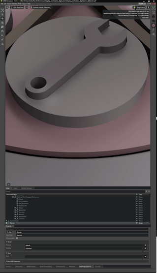
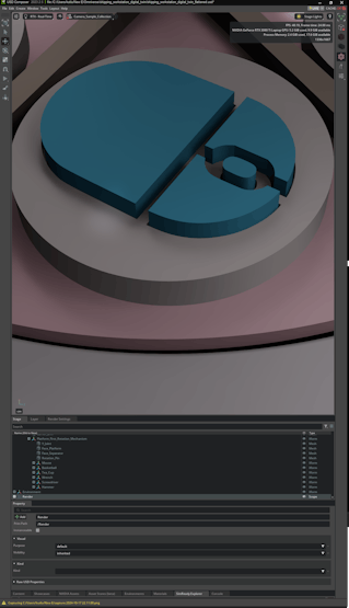
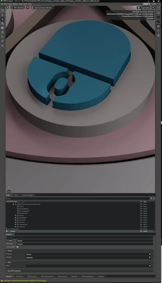
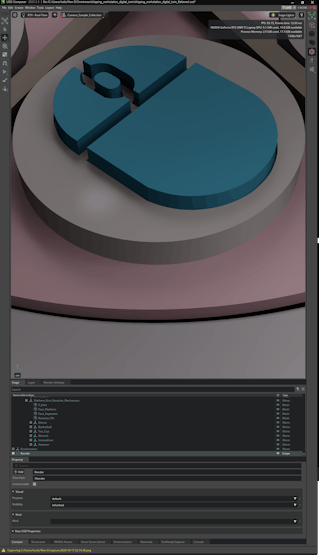
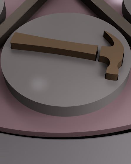
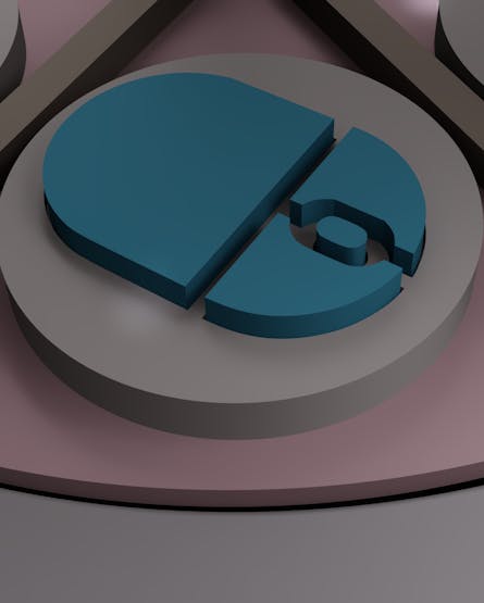
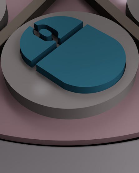
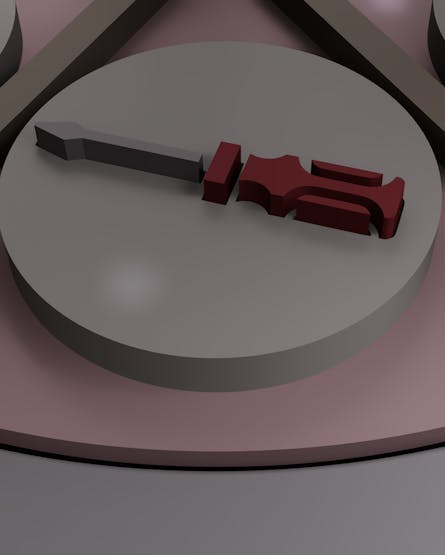
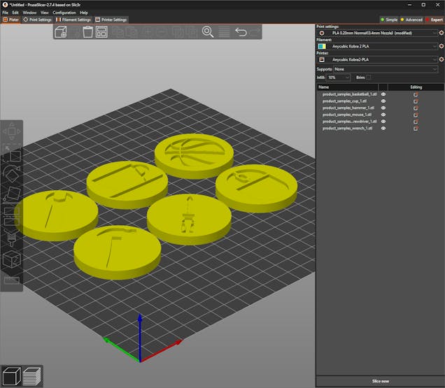
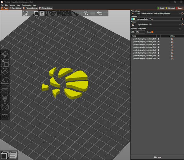
#️⃣ Compatible with the platform face separators, I designed multipart enamel pin-inspired 3D models as virtual sample products representing these objects:
- Wrench
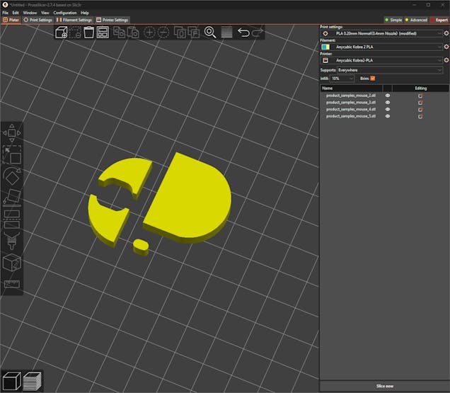
- Mouse
- Basketball
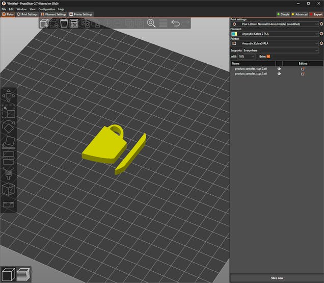
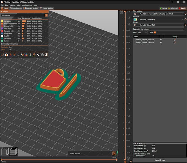
- Teacup
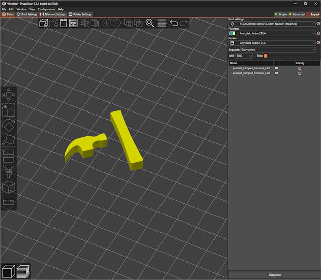
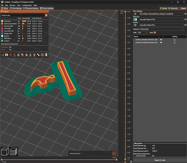
- Hammer
- Screwdriver
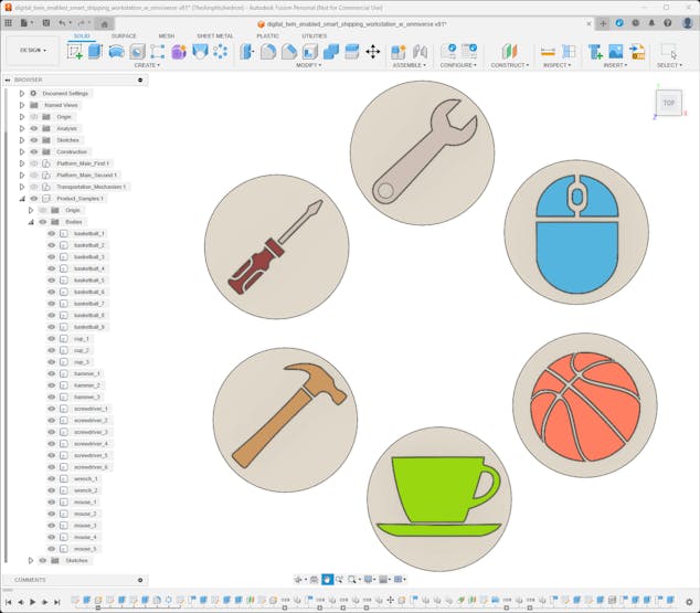

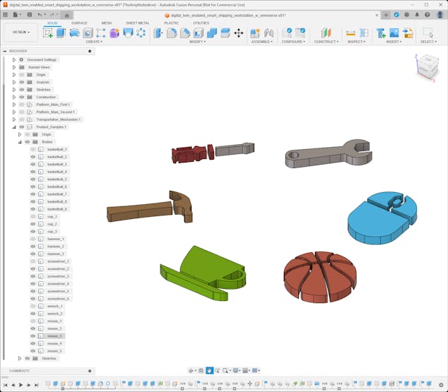
Step 3.0: Setting up the NVIDIA Omniverse Launcher
NVIDIA Omniverse™ is a versatile and developer-friendly platform integrating OpenUSD (Universal Scene Description) and NVIDIA RTX™ rendering technologies into existing software tools and simulation workflows with officially supported APIs, SDKs, and services. In this regard, NVIDIA Omniverse provides all the necessary building tools to envision and realize large-scale and AI-enabled virtual worlds.
Since NVIDIA Omniverse is a platform optimized for industrial digitalization and physical AI simulation and provides lots of easy-to-use tools for 3D world (environment) modeling, I decided to capitalize on its enhanced simulation and rendering features while building my shipping workstation digital twin. As NVIDIA states, various enterprises employ Omniverse's state-of-the-art services to develop digital twins as testing grounds to design, simulate, operate, and optimize their products and production facilities.
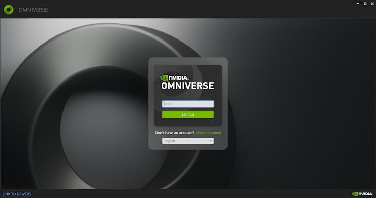
Even though NVIDIA Omniverse provides developers with the NVIDIA Omniverse Kit SDK to build OpenUSD-native applications and extensions for specific tasks, I decided to utilize the Omniverse Launcher as a single-user workstation, which gives access to all Omniverse services required to build my physically accurate shipping workstation digital twin.
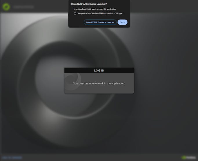
#️⃣ First, install the Omniverse Launcher here.
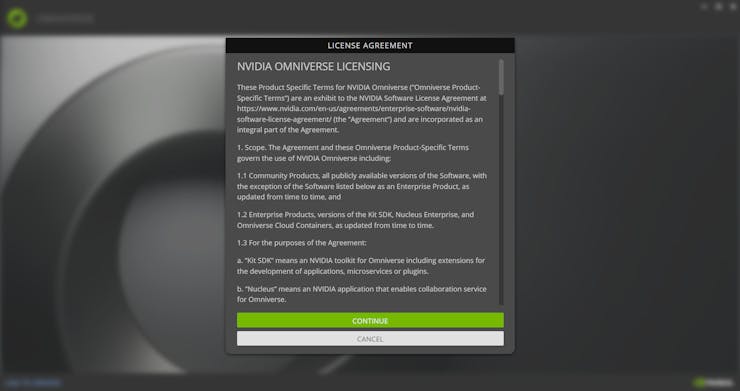
#️⃣ Then, create an NVIDIA account and confirm the license agreement to initiate the single-user workstation.
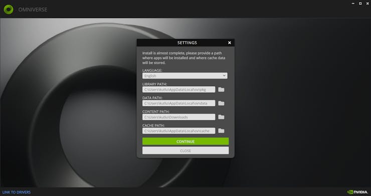
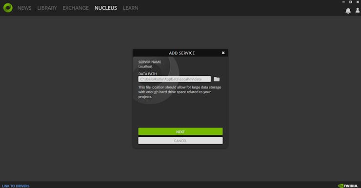
#️⃣ Assign paths to store the necessary Omniverse Launcher information locally.
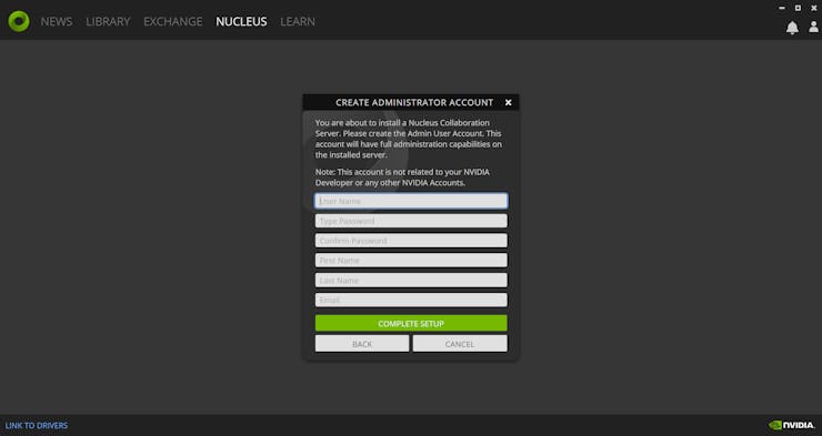
#️⃣ Since the Omniverse Launcher requires a Nucleus Collaboration Server to access all available apps, services, and assets, create a local Nucleus server and its administration account.
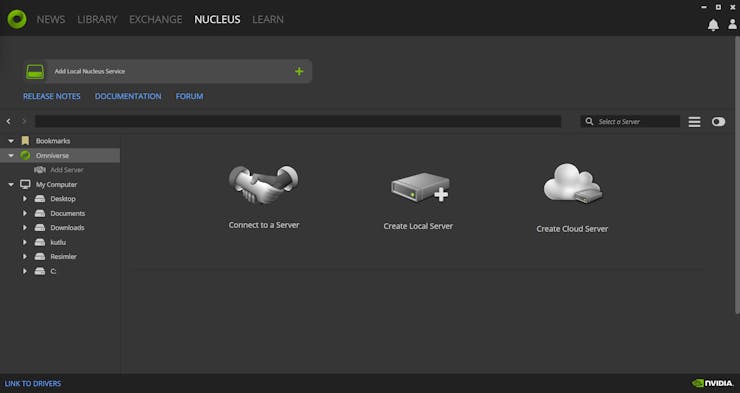

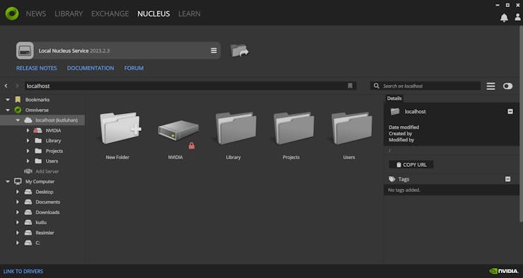
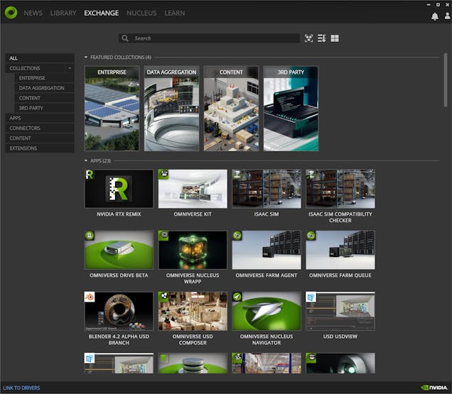
#️⃣ After establishing the local Nucleus server (service), the Launcher shows all available applications, services, connectors, and content on the Exchange tab.
Step 3: Forming the shipping workstation digital twin on NVIDIA Omniverse USD Composer
The Omniverse USD Composer is an application built on the Omniverse Kit and provides advanced layout tools and simulation capabilities, including but not limited to NVIDIA RTX™ Renderer and physics extension, for generating visually compelling and physically accurate worlds.
Since the USD Composer allows developers to import existing assets (designs) and render large-scale scenes with user-friendly simulation tools, I decided to set up the USD Composer on the Omniverse Launcher to build my shipping workstation digital twin.
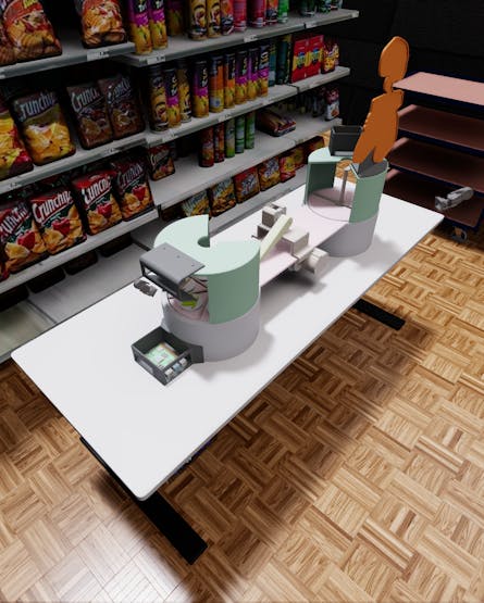
After installing the USD Composer, I started to work on producing a realistic scenery for industrial-level shipping operations.
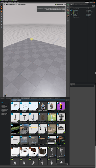
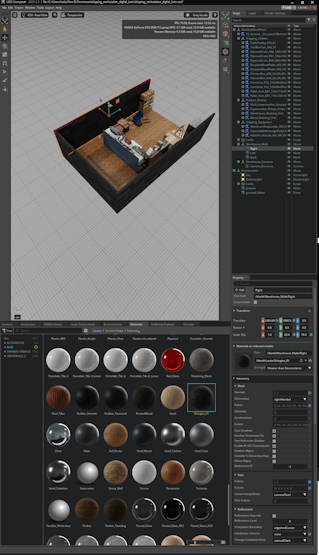
Plausibly, NVIDIA Omniverse provides built-in asset (3D model) and material libraries for various use cases. Also, the USD Composer includes the Asset Store displaying all available high-quality 3D models from diverse third-party content libraries.
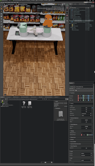
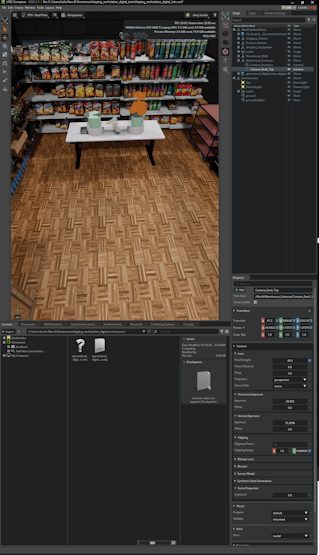
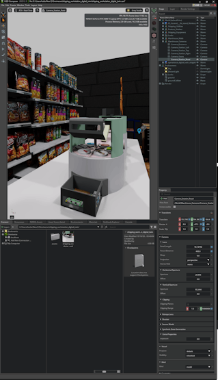
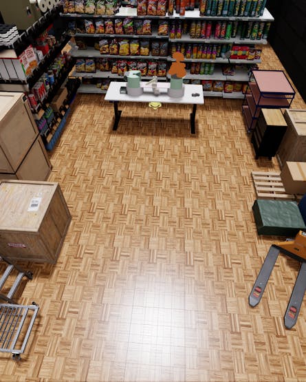
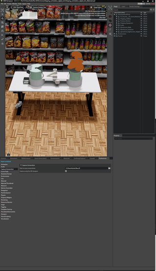
#️⃣ First, I scrutinized all available assets provided by Omniverse (default) and Sketchfab (free Creative Commons-licensed) to produce a suitable scenery, including a close replica of my standing desk.
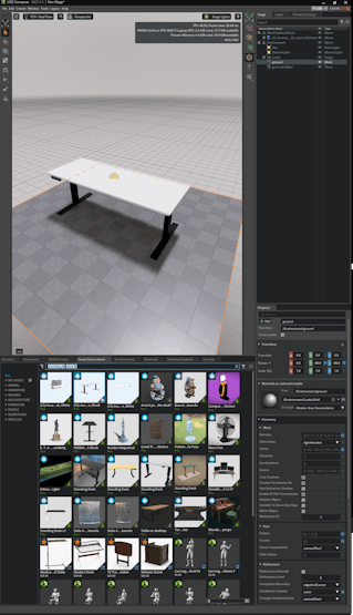
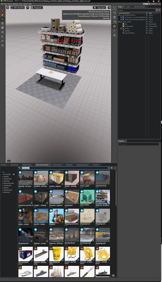
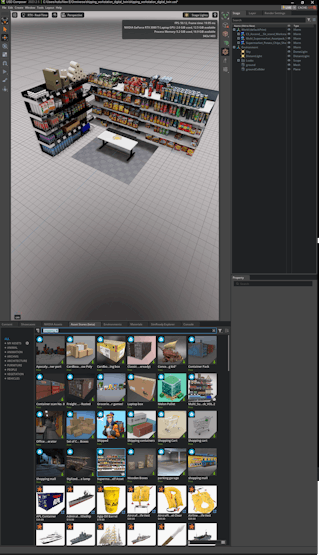

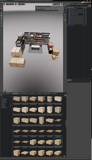
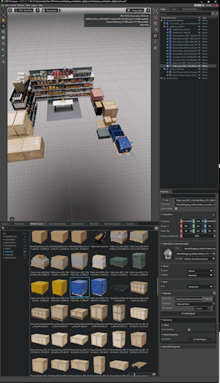
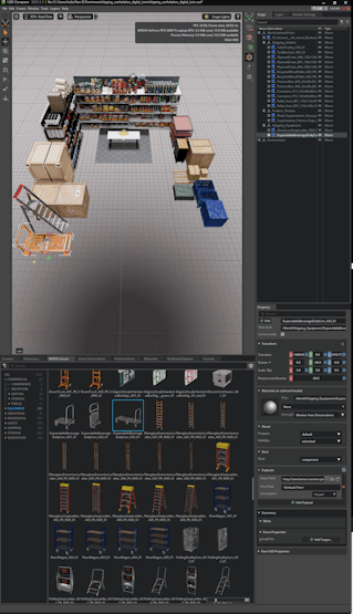
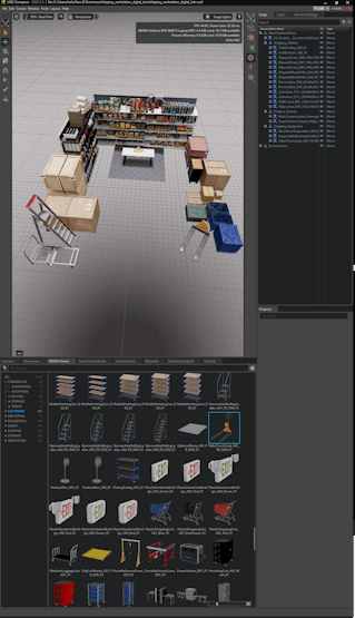
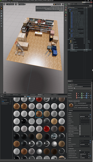
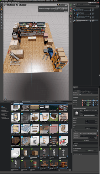
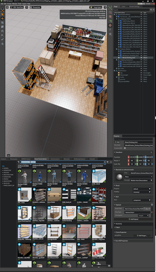
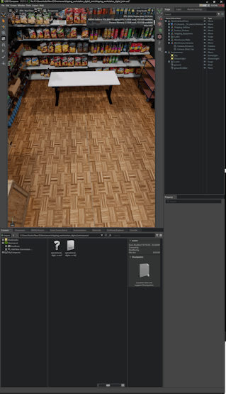
#️⃣ Then, I designed some custom assets with the integrated Omniverse tools to finalize my shipping warehouse scenery.
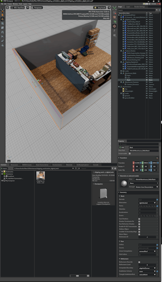
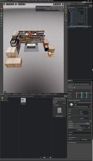
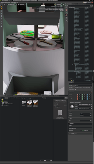
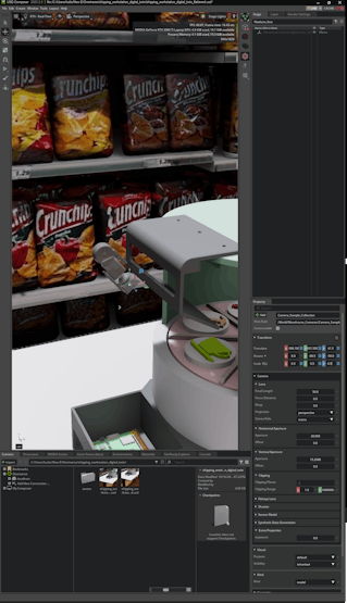
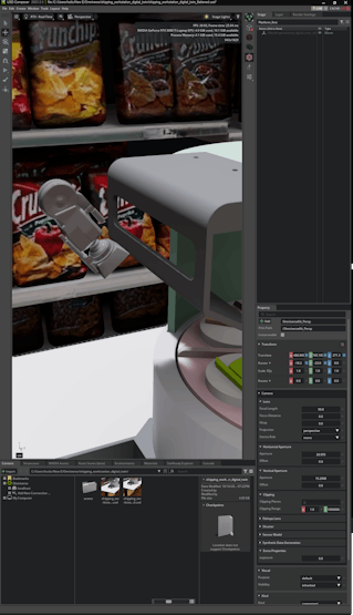
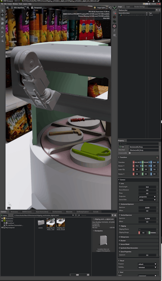
#️⃣ After completing my shipping warehouse scenery, I imported the virtual shipping workstation in the OBJ format.
#️⃣ Since the Omniverse Launcher can automatically detect and assign Fusion 360 material, color, and texture configurations, the USD Composer rendered the virtual shipping workstation to produce a flawless digital twin.
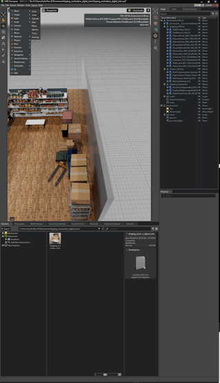
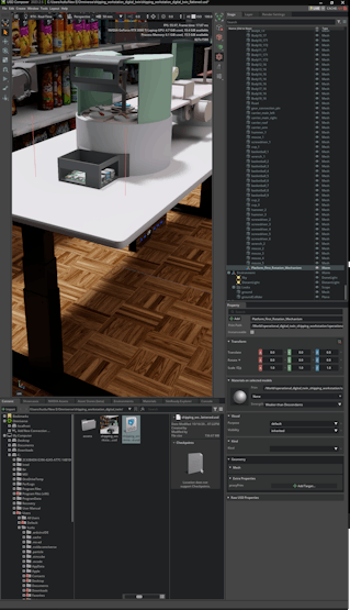
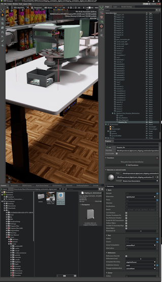
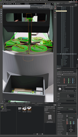
#️⃣ To move the first rotating platform and sample products as a single object via the physics extension, I tried to group all associated models under a new Xform. However, it was not possible since these models were references from the original OBJ file.
#️⃣ To solve this issue, I saved the Omniverse stage again by utilizing the Save Flattened As option to merge all 3D models. Then, I was able to modify and group the associated models easily.


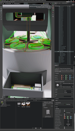
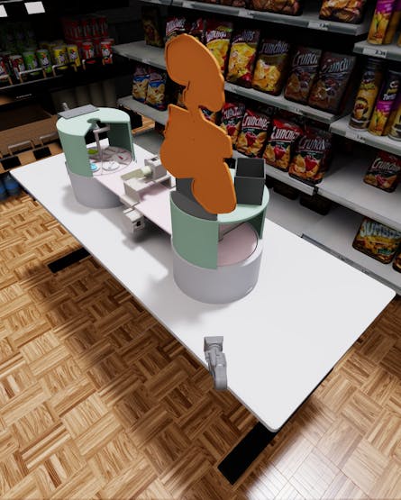
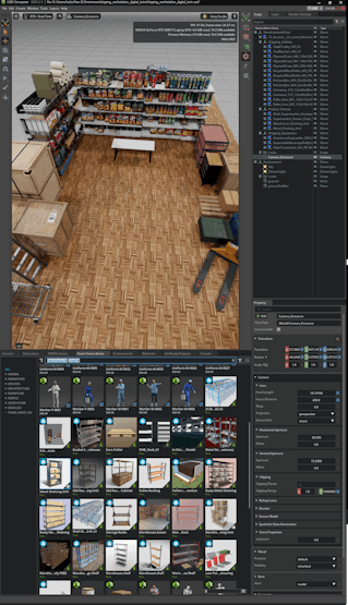
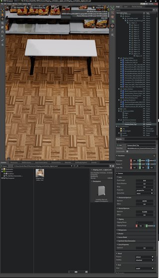
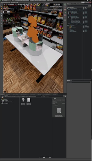
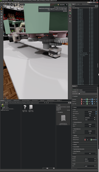
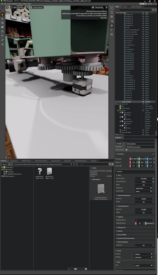
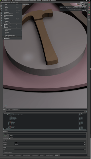
#️⃣ After producing the shipping workstation digital twin, I created a few cameras to survey the virtual workstation and capture synthetic sample product images effortlessly.


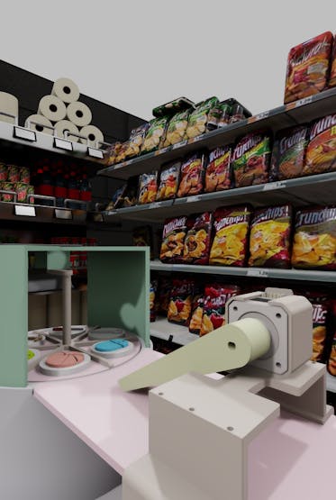
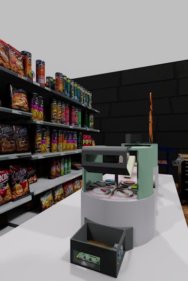
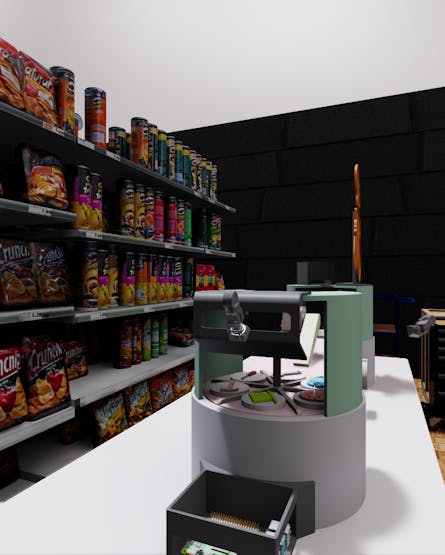

Step 4: Constructing a synthetic data set of customized sample products via NVIDIA Omniverse
#️⃣ After preparing the shipping workstation digital twin for synthetic data collection, I experimented with camera, lighting, and rendering configurations to create optimal conditions.
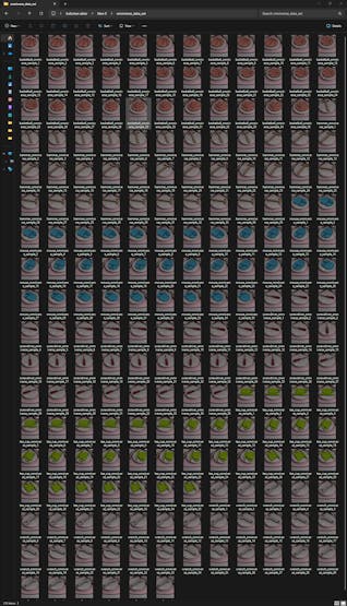
#️⃣ Then, I applied the built-in Capture Screenshot (F10) feature by activating the Capture only the 3D viewport option so as to construct my synthetic data set of unique sample products in various poses.
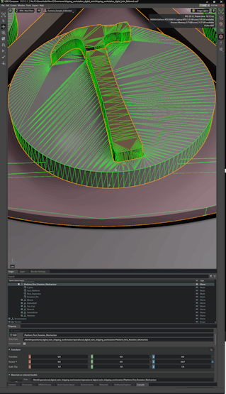
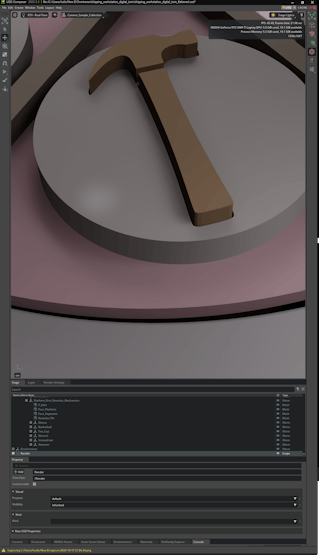
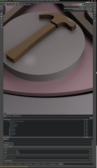
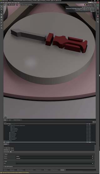
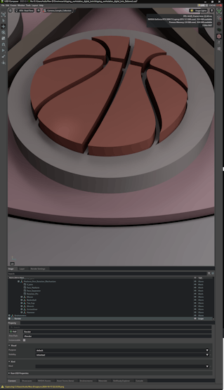
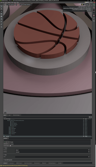
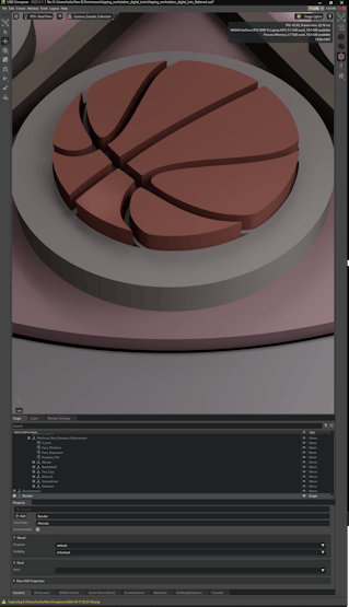
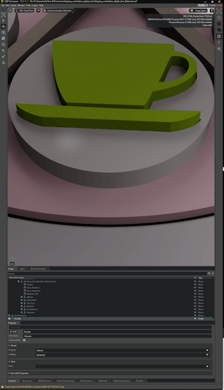
🖼️ Synthetic data samples:


Step 5: Setting up LAMP web server, Edge Impulse CLI, and Linux Python SDK on Raspberry Pi 5
After constructing my synthetic data set, I was going to build my object detection model before proceeding with real-world shipping workstation preparations. However, while trying to upload my synthetic data samples generated by NVIDIA Omniverse USD Composer, I noticed most of them were refused by the Edge Impulse data uploader by being tagged as duplicated. I even attempted to upload six individual samples for each product, nonetheless, the issue still resumed. Thus, I decided to set up Raspberry Pi 5 earlier to perform the tasks required by the real-world shipping workstation and upload samples directly.
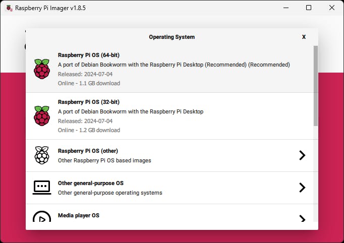
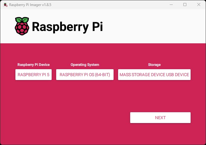
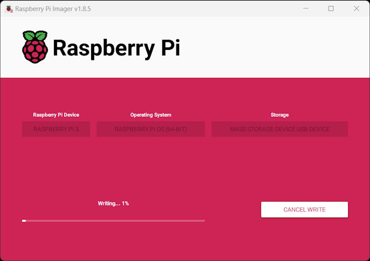
#️⃣ First, I installed the Raspberry Pi 5-compatible operating system image on a microSD card and initiated Raspberry Pi 5.
❗⚡ Note: While testing peripherals, I encountered under-voltage issues and purchased the official Raspberry Pi 5 27W USB-C power supply.
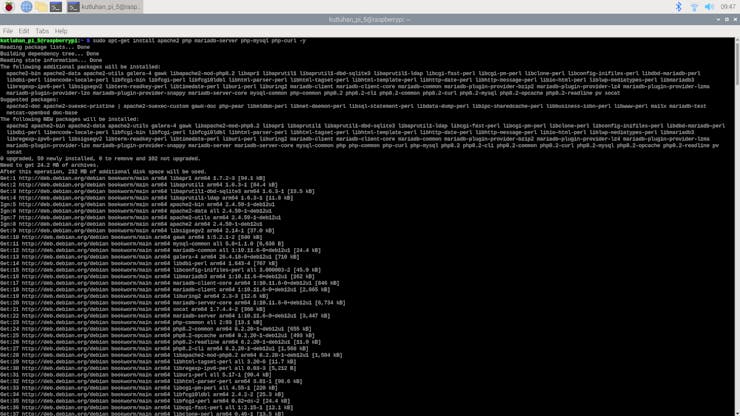
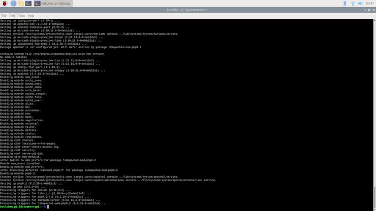
#️⃣ After initiating Raspberry Pi 5 successfully, I set up an Apache web server with a MariaDB database. I also installed PHP MySQL and cURL packages to host and enable the web workstation application features.
sudo apt-get install apache2 php mariadb-server php-mysql php-curl -y
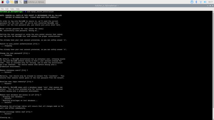
#️⃣ To utilize the MariaDB database, I created a new user and followed the secure installation prompt.
sudo mysql_secure_installation
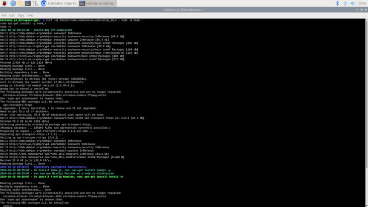
#️⃣ After setting up the LAMP web server, I installed the Edge Impulse CLI by following the official instructions for Raspbian OS.
#️⃣ First, I downloaded the latest Node.js version since versions older than 20.x may lead to installation issues or runtime errors.
curl -sL https://deb.nodesource.com/setup_20.x | sudo -E bash -
sudo apt-get install -y nodejs
node -v
#️⃣ Then, I installed the available CLI tools.
npm install -g edge-impulse-cli
#️⃣ After setting up the Edge Impulse CLI, I installed the Edge Impulse Linux Python SDK to run Edge Impulse machine learning models via Python.
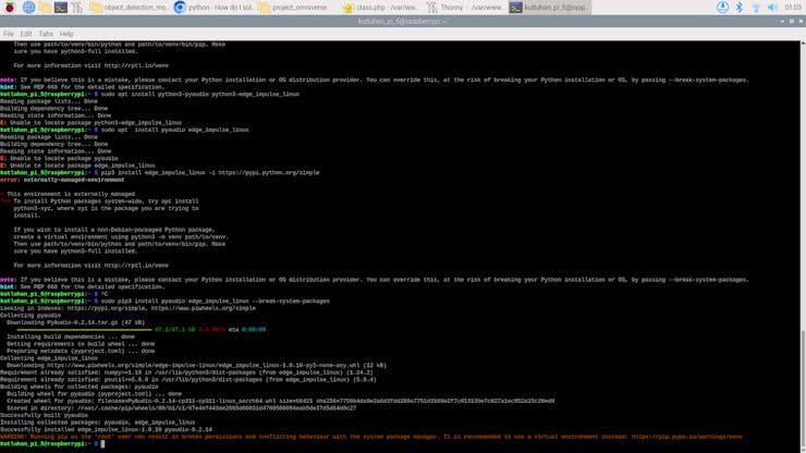
❗ If you do not run a virtual environment on Pi 5, the system may throw an error while trying to install packages via pip. To simply solve this issue, you can add --break-system-packages.
sudo apt-get install libatlas-base-dev libportaudio2 libportaudiocpp0 portaudio19-dev python3-pip
sudo pip3 install pyaudio edge_impulse_linux --break-system-packages

Step 6: Building an object detection model (FOMO) w/ Edge Impulse Enterprise
Since Edge Impulse provides developer-friendly tools for advanced AI applications and supports almost every development board due to its model deployment options, I decided to utilize Edge Impulse Enterprise to build my object detection model. Also, Edge Impulse Enterprise incorporates elaborate model architectures for advanced computer vision applications and optimizes the state-of-the-art vision models for edge devices and single-board computers such as Raspberry Pi 5.
Among the diverse machine learning algorithms provided by Edge Impulse, I decided to employ FOMO (Faster Objects, More Objects) since it is a novel algorithm optimized for highly constrained devices with a brilliant heat map to bounding boxes technique.
While labeling my synthetic image samples, I simply applied the names of the represented real-world objects:
- wrench
- mouse
- basketball
- tea_cup
- hammer
- screwdriver
Plausibly, Edge Impulse Enterprise enables developers with advanced tools to build, optimize, and deploy each available machine learning algorithm as supported firmware for nearly any device you can think of. Therefore, after training and validating, I was able to deploy my FOMO model as a Linux (AARCH64) application (.eim) compatible with Raspberry Pi 5.
You can inspect my object detection model (FOMO) on Edge Impulse as a public project.
Step 6.1: Uploading and labeling training and testing images (samples)
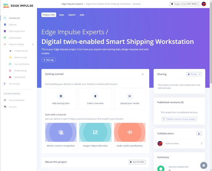
#️⃣ To utilize the advanced AI tools provided by Edge Impulse, register here and create a new project.
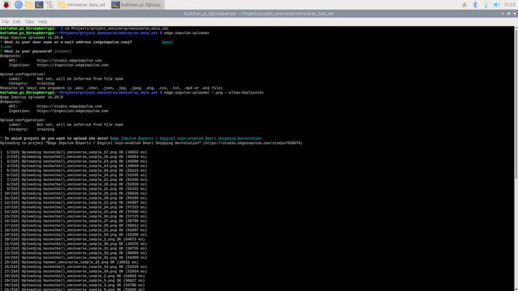
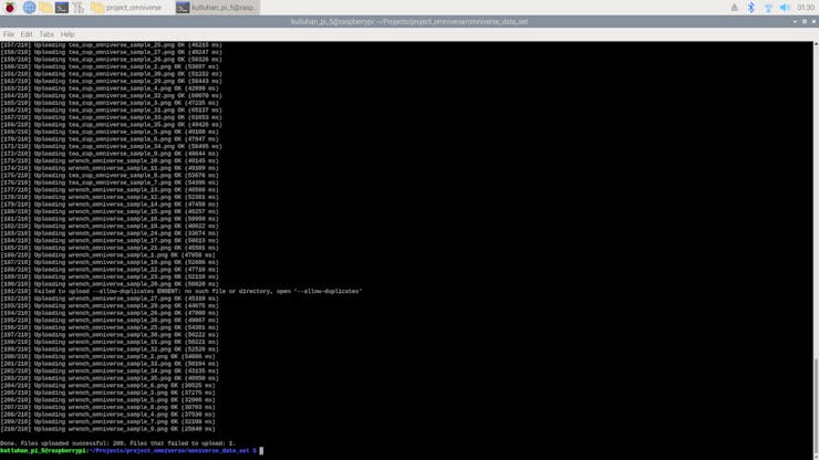
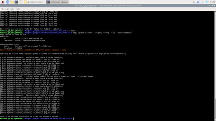
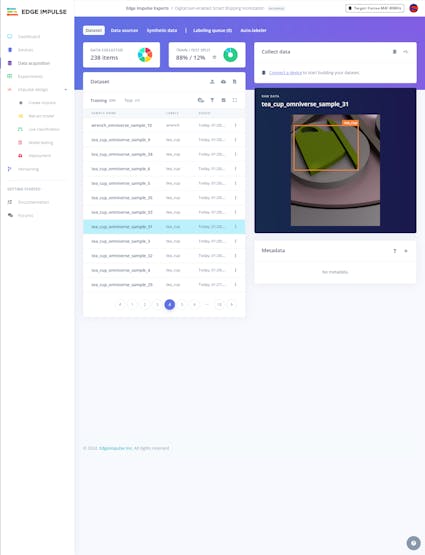
As mentioned earlier, the Edge Impulse data uploader refused most of the synthetic image samples generated by the Omniverse USD Composer. Thus, I set up the Edge Impulse CLI to upload my synthetic data set from Raspberry Pi 5 to my Edge Impulse project directly.
Since the Edge Impulse CLI allows developers to override duplicate sample detection, I was able to upload all of my synthetic data set as training and testing samples without any problem.
❗ Use --category to choose the data category (training or testing) and add --allow-duplicates to override duplicate detection.
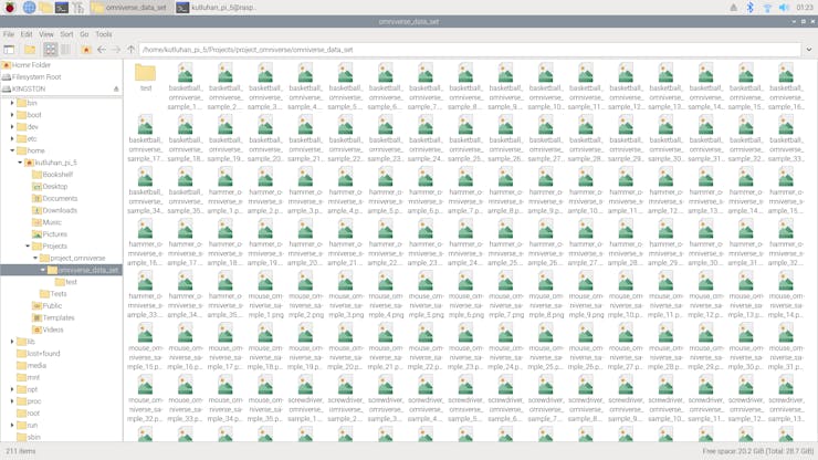
cd Projects/project_omniverse/omniverse_data_set
edge-impulse-uploader *.png --allow-duplicates
edge-impulse-uploader --category testing *.png --allow-duplicates
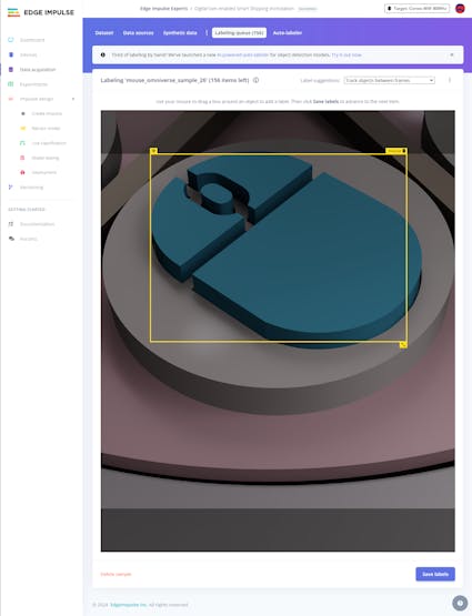
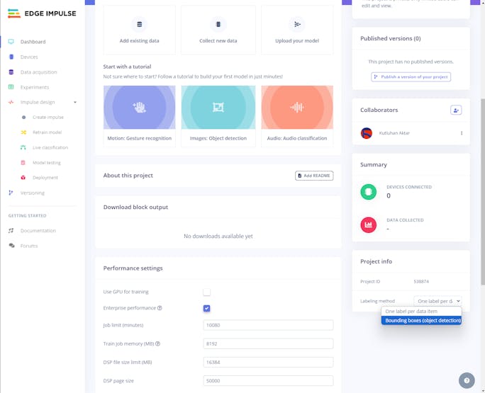
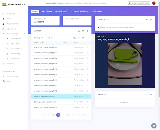
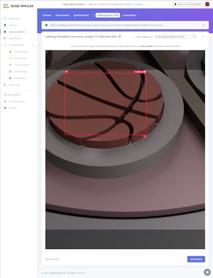
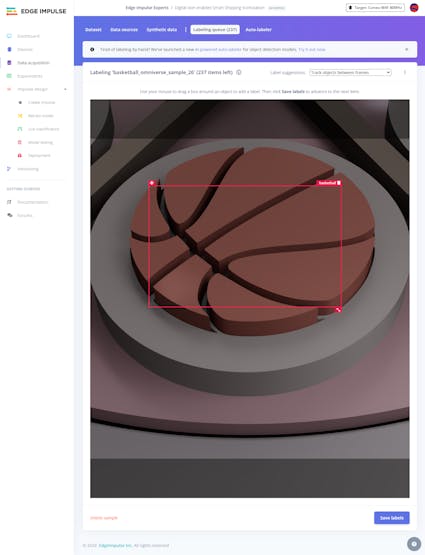
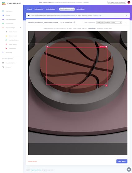
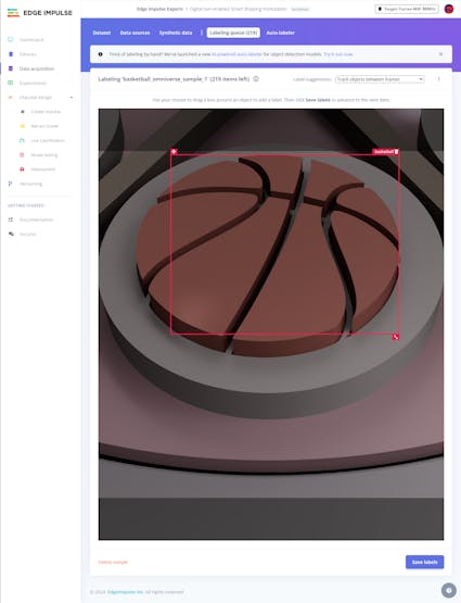
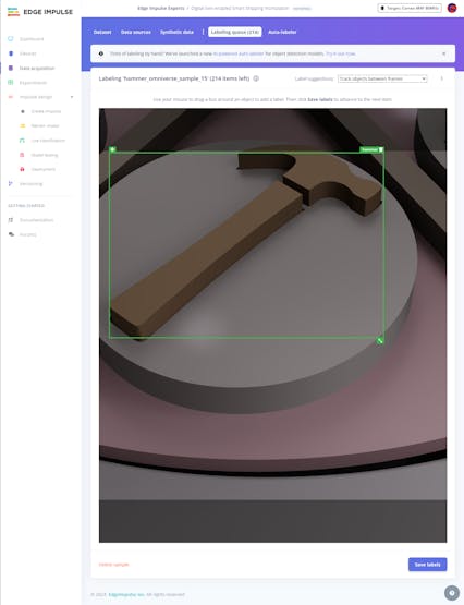
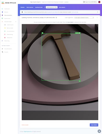
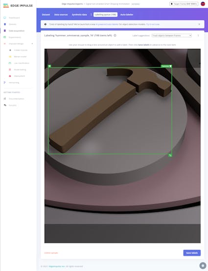
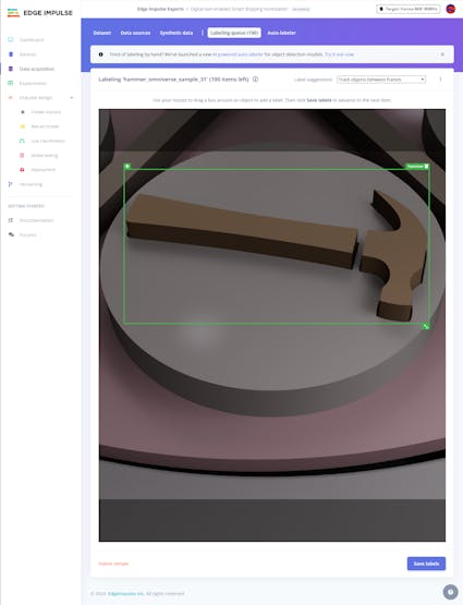
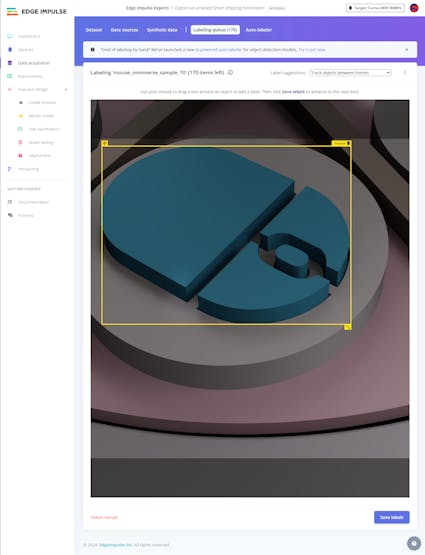
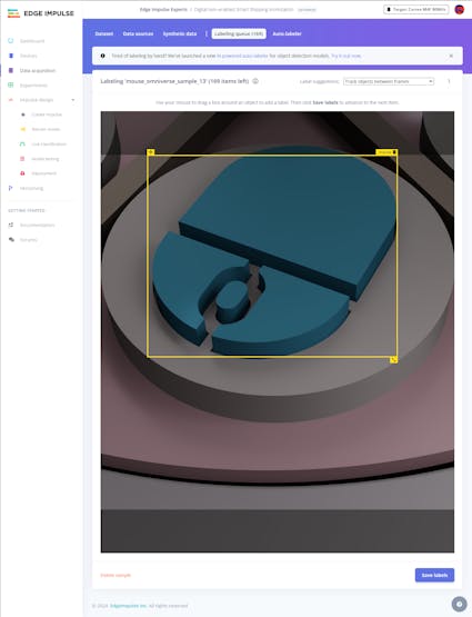
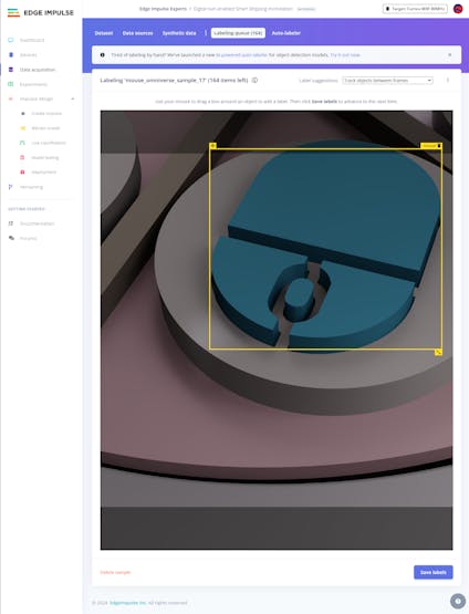
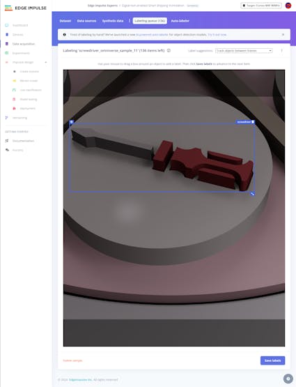
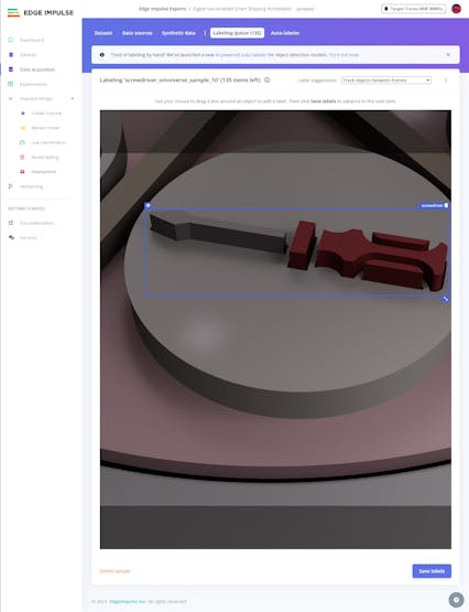
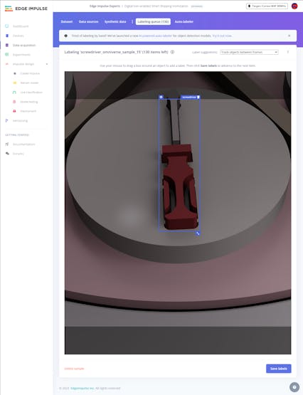
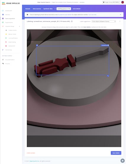
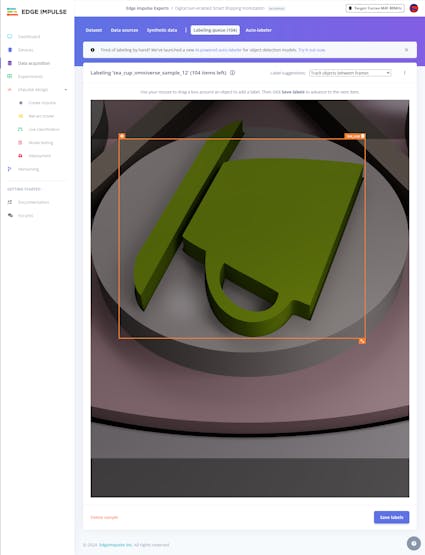
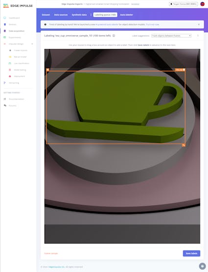
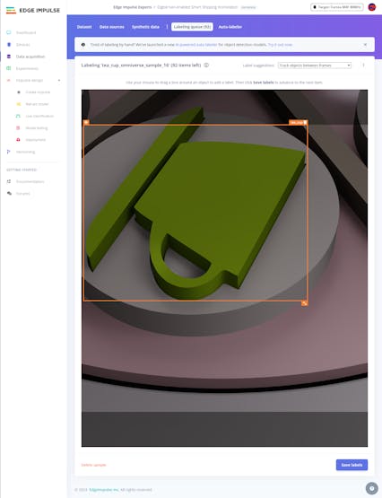
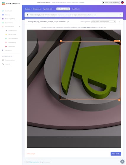
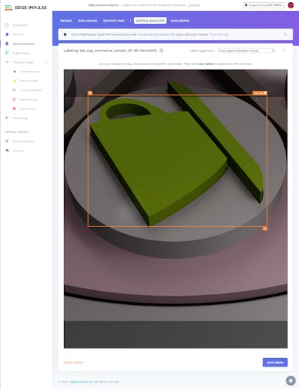
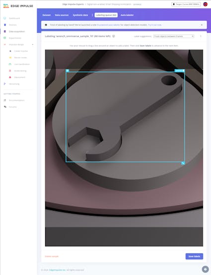
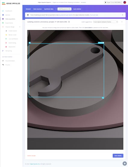
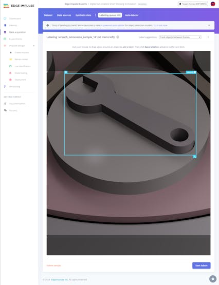
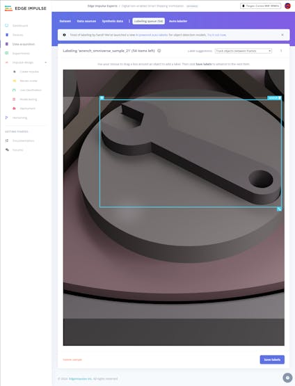
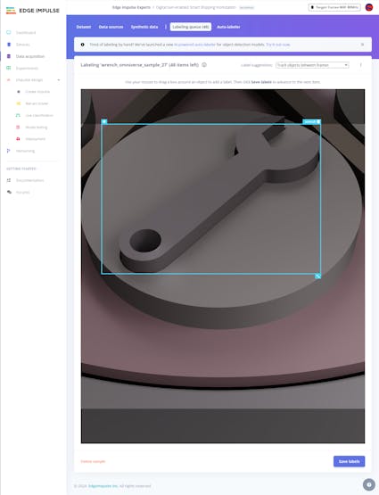
#️⃣ To employ the bounding box labeling tool for object detection models, go to Dashboard ➡ Project info ➡ Labeling method and select Bounding boxes (object detection).
After uploading my synthetic data set of unique sample products and activating the bounding box labeling tool, I started to draw bounding boxes around the target objects for each image sample.
#️⃣ Go to Data acquisition ➡ Labeling queue to access all unlabeled items (training and testing) remaining in the given data set.
#️⃣ After drawing bounding boxes around target objects, click the Save labels button to label an image sample. Then, repeat this process until all samples have at least one labeled target object.


Step 6.2: Training the FOMO model on synthetic sample product images
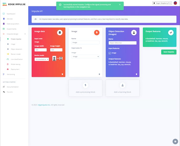
An impulse is a custom machine learning application processed and optimized by Edge Impulse. I created my impulse by employing the Image processing block and the Object Detection (Images) learning block.
The Image processing block optionally turns the input image format to grayscale or RGB and generates a features array from the passed raw image.
The Object Detection (Images) learning block represents the accessible machine learning algorithms to perform object detection.
#️⃣ Go to the Create impulse page, set the image dimensions to 320, select the Fit shortest axis resize mode so as to scale (resize) the given image samples precisely, and click Save Impulse.
#️⃣ To modify the raw features in the applicable format, go to the Image page, set the Color depth parameter as RGB, and click Save parameters.
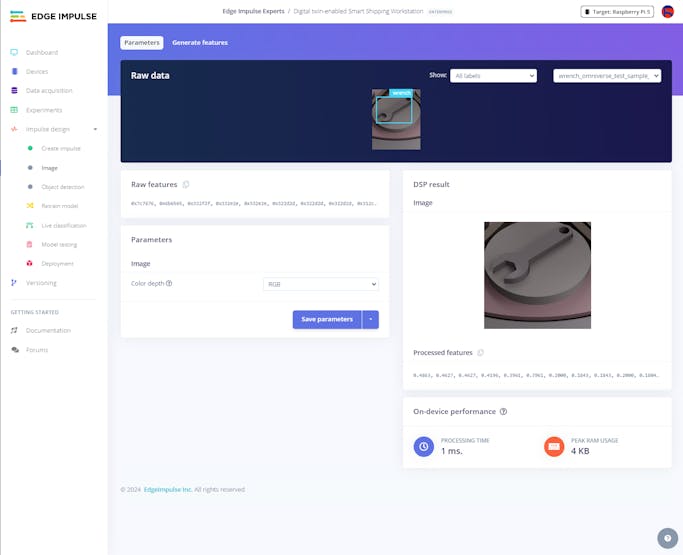
#️⃣ Then, click Generate features to apply the Image processing block to training image samples.
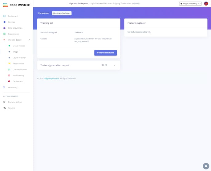
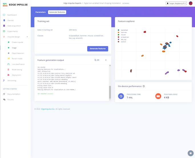
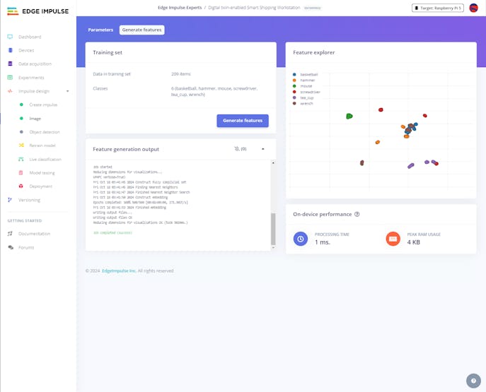
#️⃣ After generating features successfully, navigate to the Object detection page and click Start training.
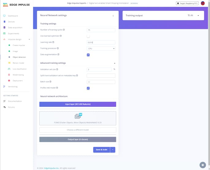
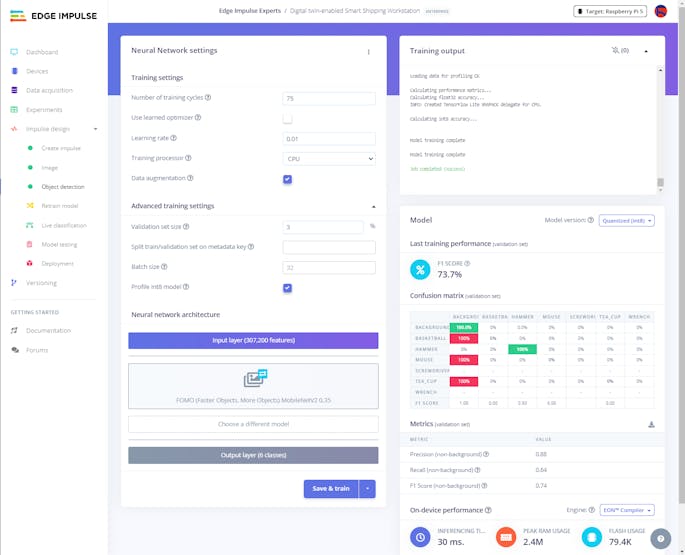
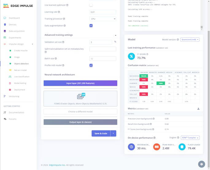
According to my prolonged experiments, I modified the neural network settings and architecture to achieve reliable accuracy and validity:
📌 Neural network settings:
- Number of training cycles ➡ 75
- Learning rate ➡ 0.010
- Validation set size ➡ 3%
📌 Neural network architecture:
- FOMO (Faster Objects, More Objects) MobileNetV2 0.35
After training with the given configurations, Edge Impulse evaluated the F1 score (accuracy) as 73.7% due to the modest volume of the validation set.
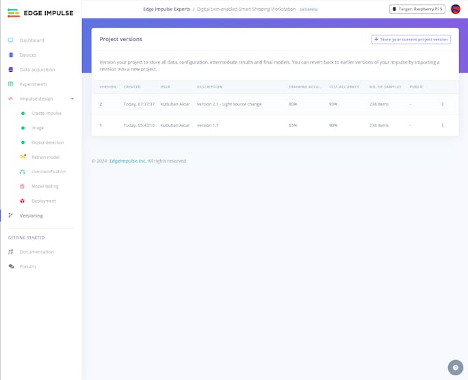
#️⃣ Since I decided to experiment with different model and simulation (render) configurations consecutively, I utilized two versions of the same model to achieve the results I wanted faster.
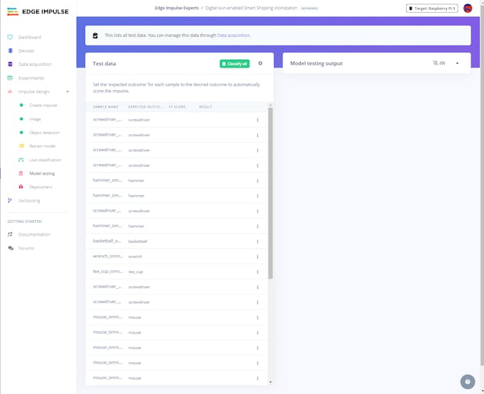
Step 6.3: Evaluating the model accuracy and deploying the validated model
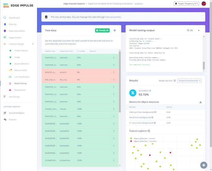
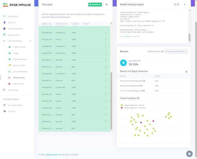
By applying the given testing samples, Edge Impulse evaluated the model accuracy (precision) as 93.10%.
#️⃣ To validate the trained model, go to the Model testing page and click Classify all.
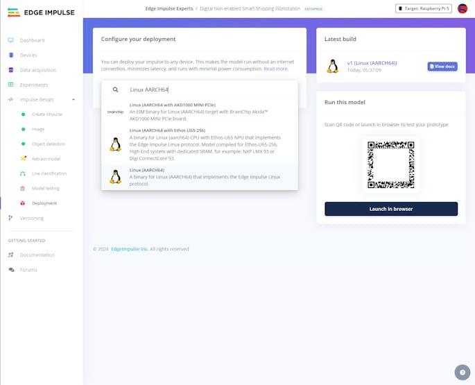
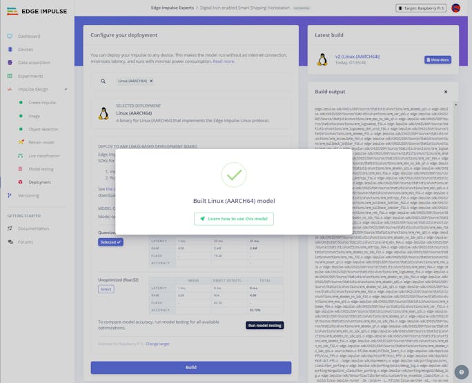
Then, I deployed the validated model as a fully optimized and customizable Linux (AARCH64) application (.eim).
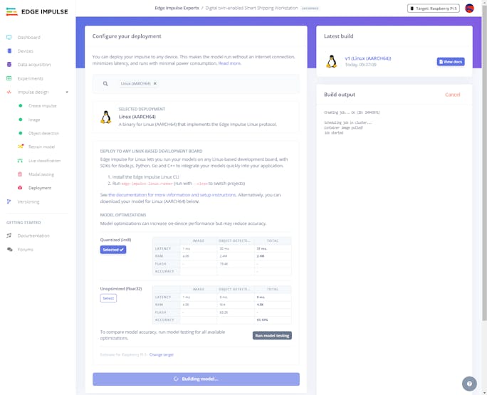
#️⃣ Navigate to the Deployment page and search for Linux (AARCH64).
#️⃣ Choose the Quantized (int8) optimization option to get the optimum performance while running the deployed model.
#️⃣ Finally, click Build to download the model as a Linux (AARCH64) application (.eim) compatible with Raspberry Pi 5.
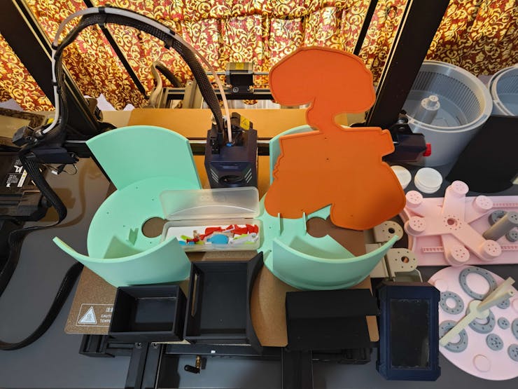
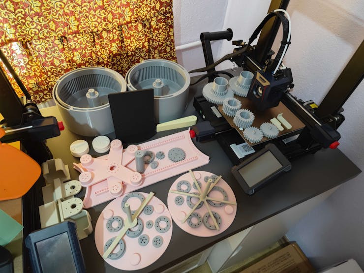
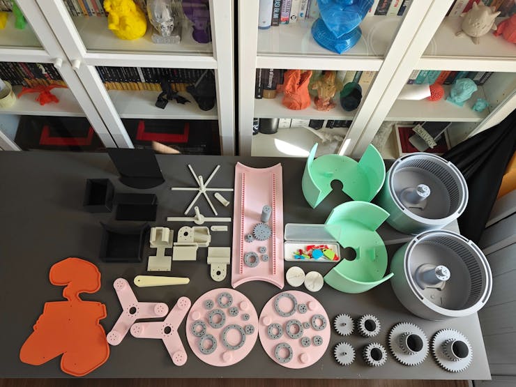
Step 7: Printing and assembling 3D parts of the virtual shipping workstation to build its real-world counterpart
After concluding my assignments with the shipping workstation digital twin on NVIDIA Omniverse USD Composer, I started to work on building its real-world counterpart.
#️⃣ First, on Autodesk Fusion 360, I exported all virtual shipping workstation 3D parts in the STL format individually.
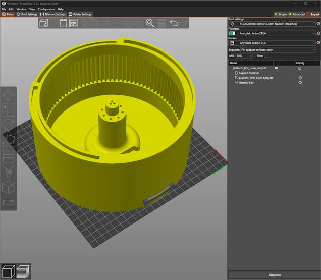
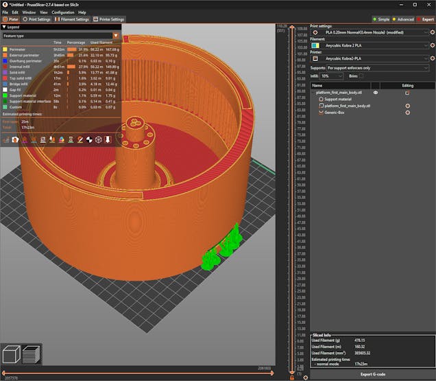
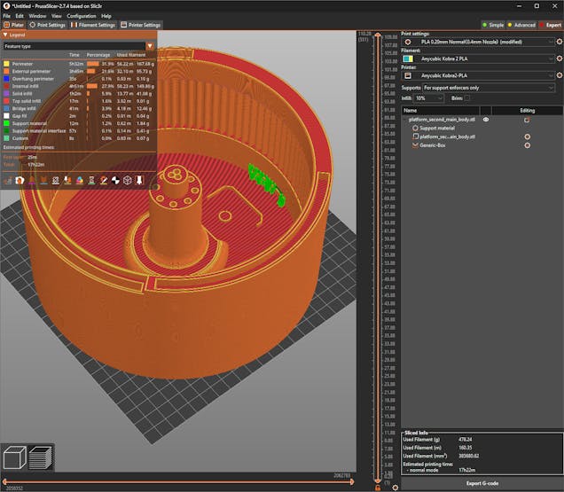
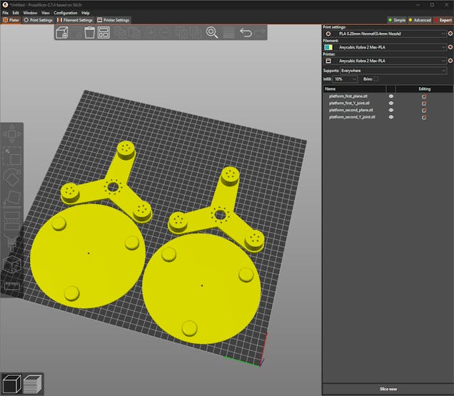
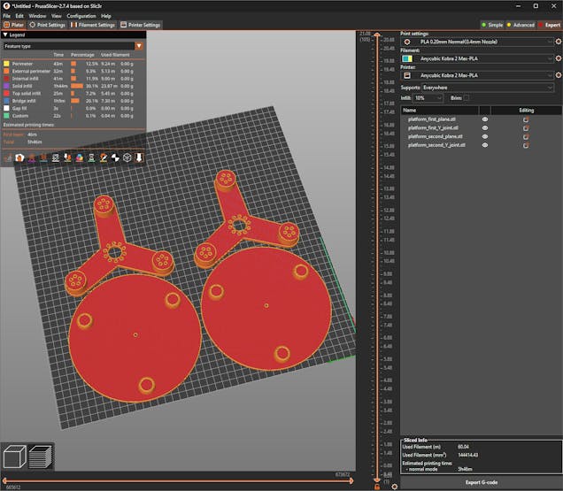
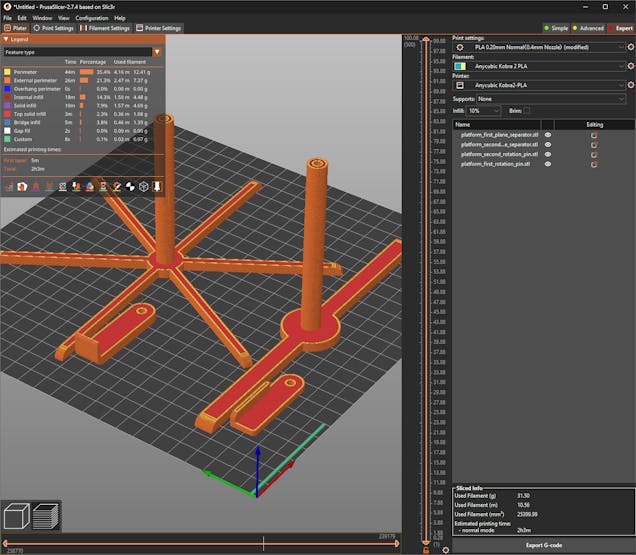
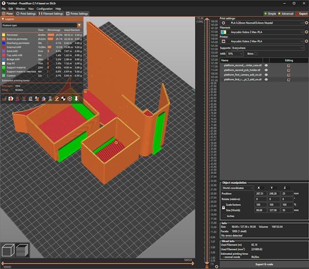
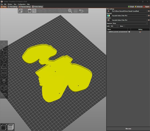
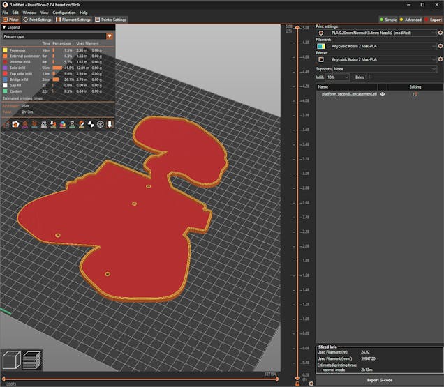
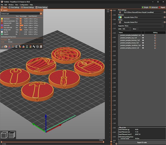
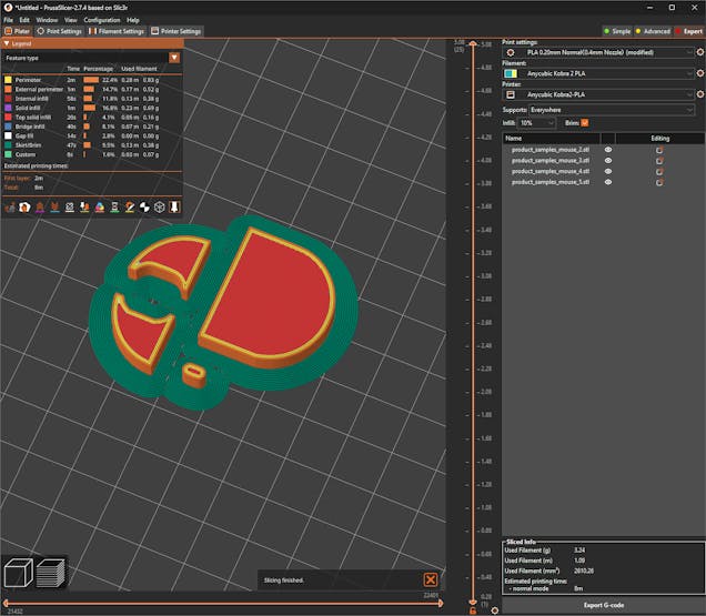
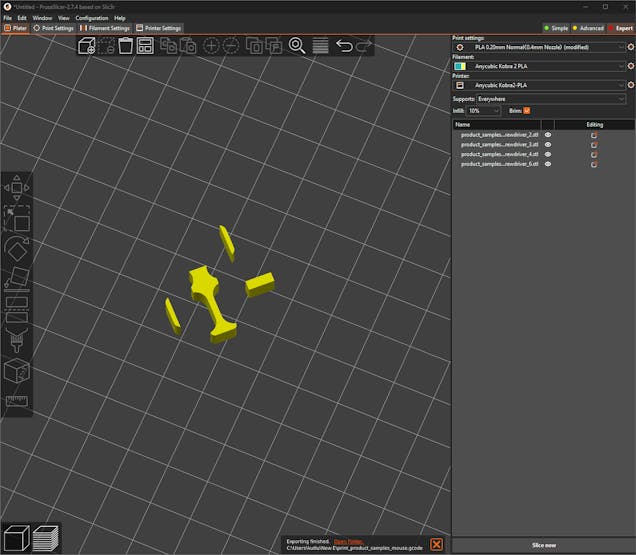
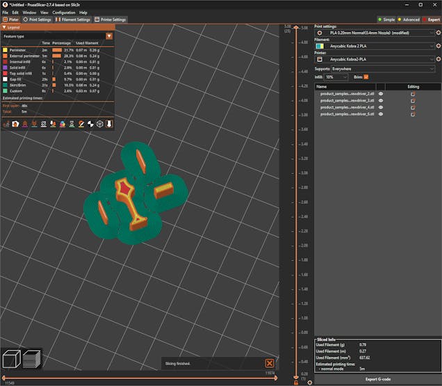
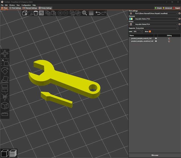
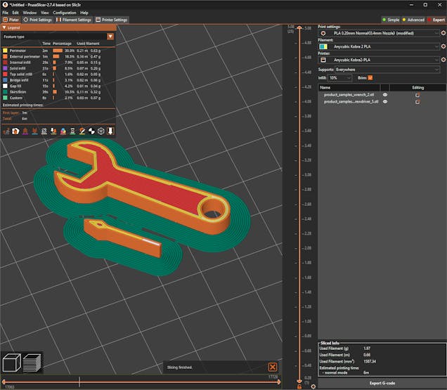
#️⃣ Then, I sliced the exported parts in PrusaSlicer, which provides lots of groundbreaking features such as paint-on supports and height range modifiers.
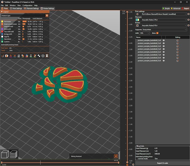
#️⃣ Due to the fluctuating part dimensions, I needed to utilize my Anycubic Kobra 2 and Kobra 2 Max 3D printers simultaneously while printing parts. Thus, I applied the relative slicer settings for each printer.
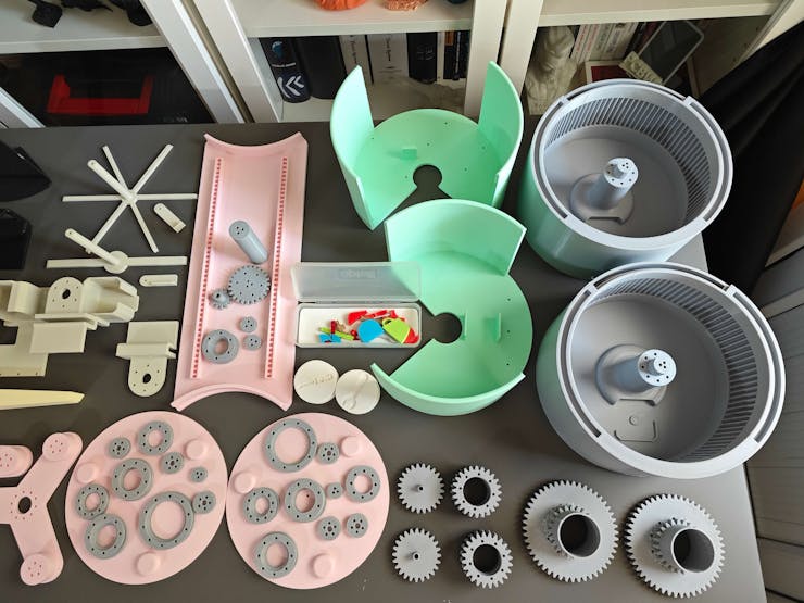
⚙️ Platforms:
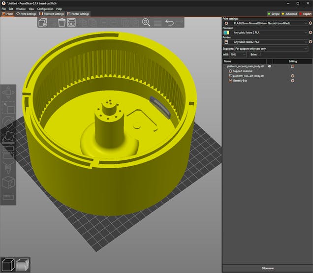
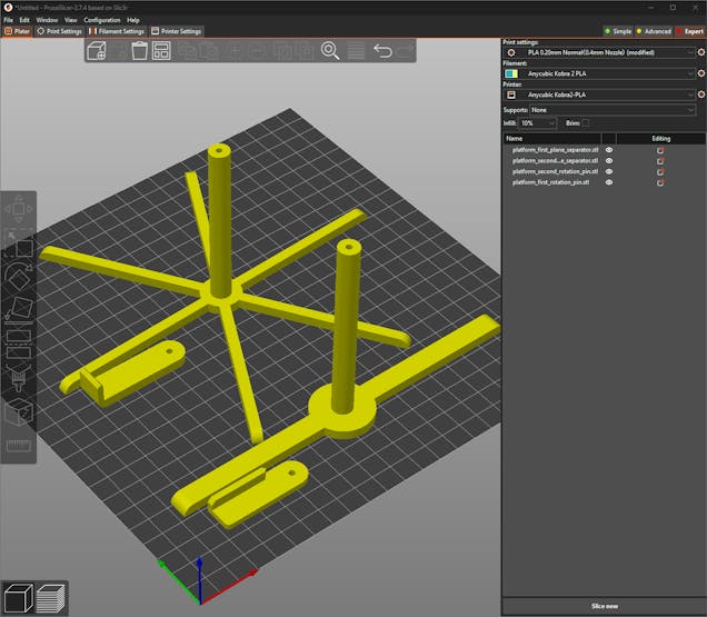

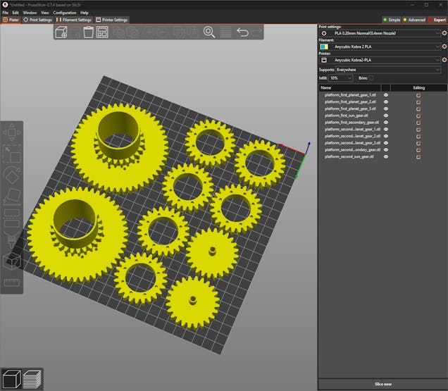
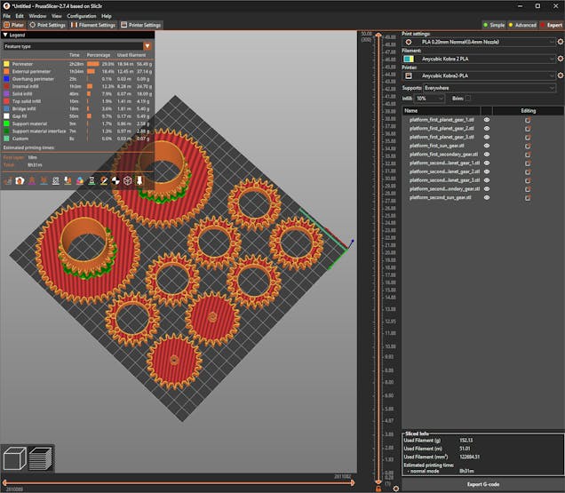
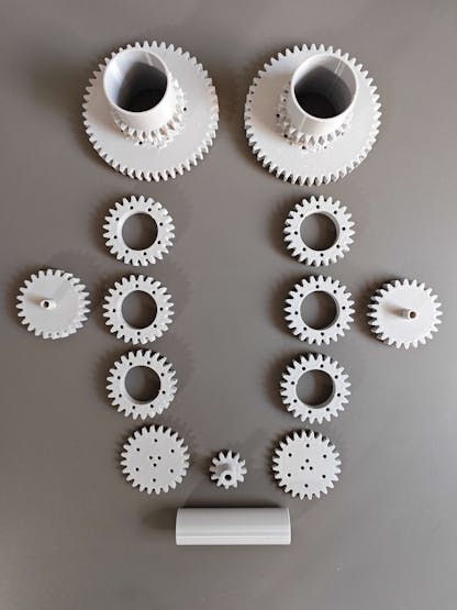
⚙️ Gears:
⚙️ Bearings:
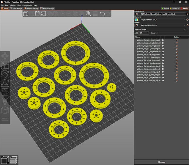
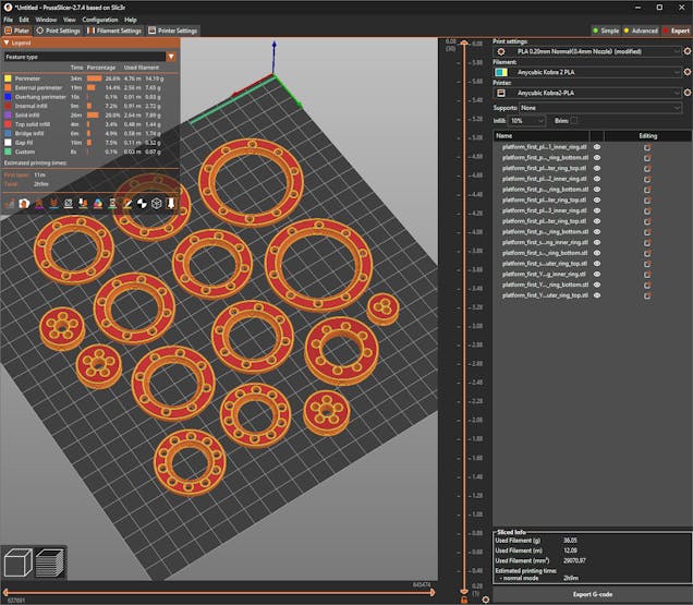
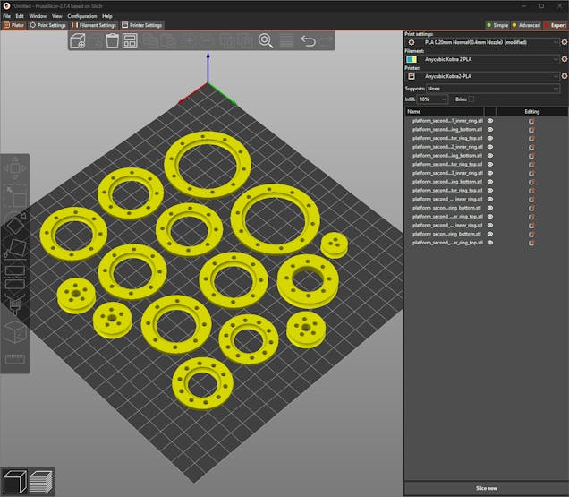

⚙️ Transportation mechanism:
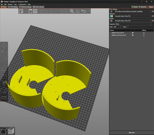
⚙️ Accessories:
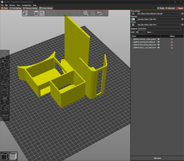
⚙️ Sample products:
As mentioned earlier, I assigned PLA filament attributes for each virtual 3D part. I utilized the exact PLA filaments to print their real-world counterparts.
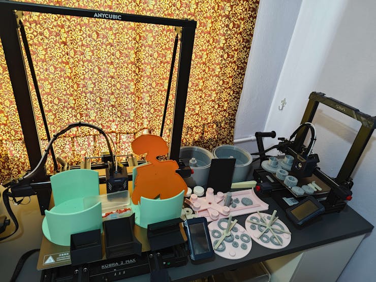
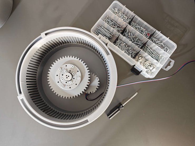
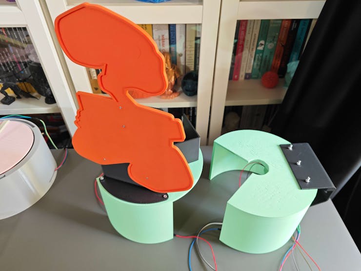
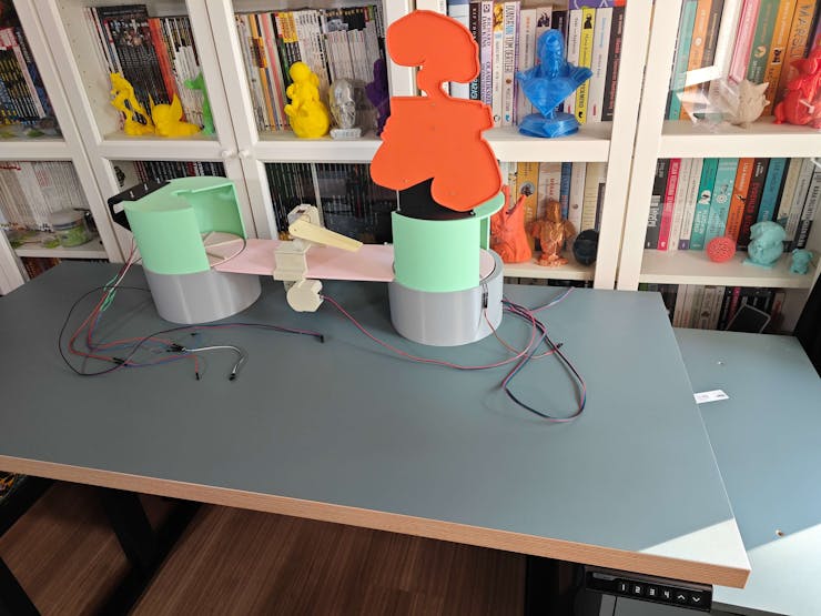
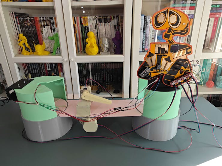
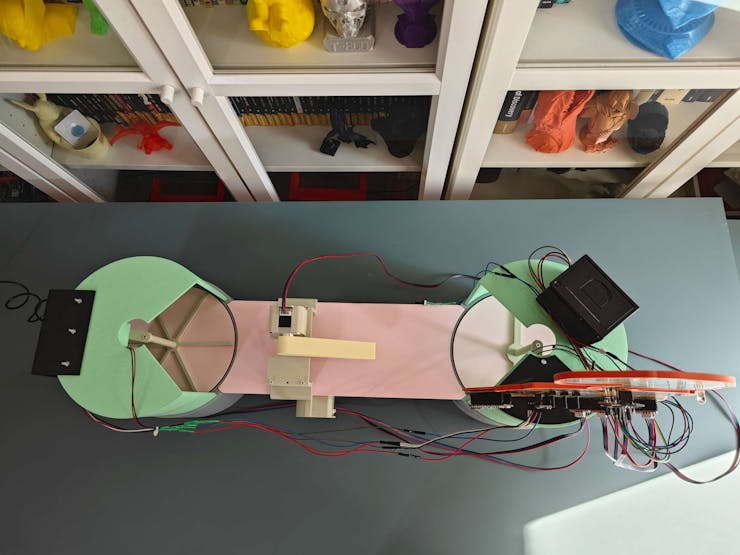
After printing all 3D parts successfully, I started to work on assembling the real-world shipping workstation.
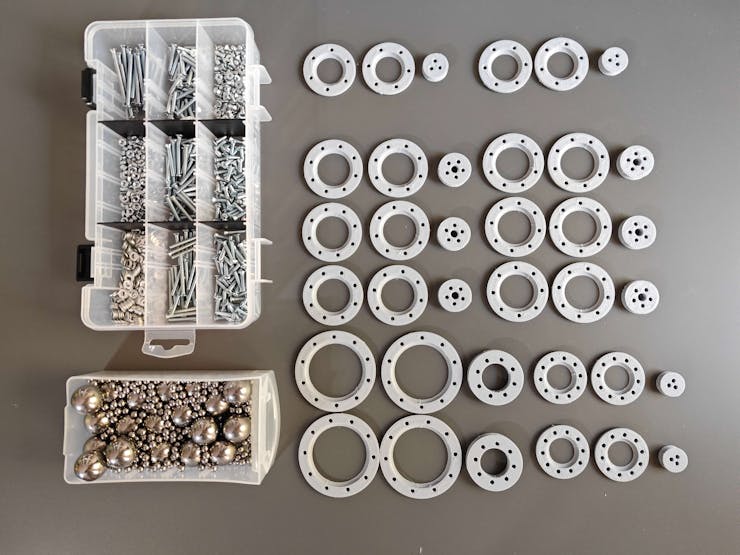
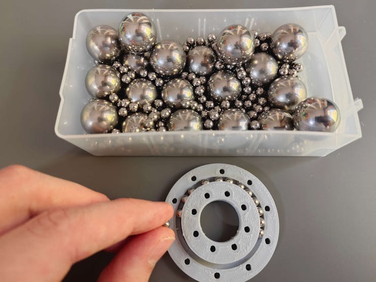
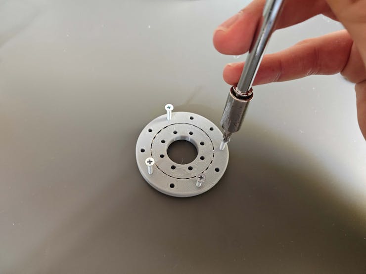
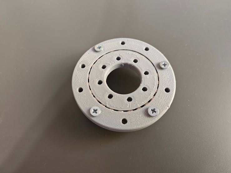
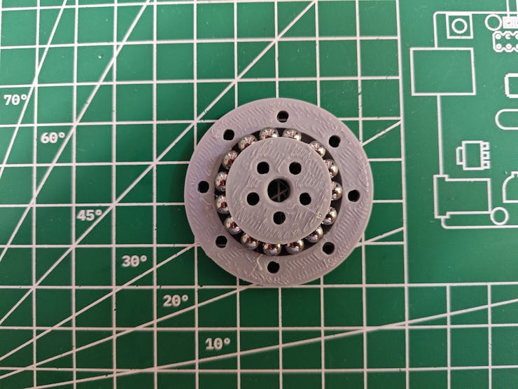
#️⃣ First, I assembled all custom ball bearings.
#️⃣ To assemble one of my custom bearings, place the required number of 5 mm steel balls between the inner ring and the bottom outer ring.
#️⃣ Then, cap the placed steel balls with the top outer ring and utilize M3 screws to adjust the bearing tightness.
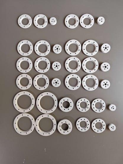
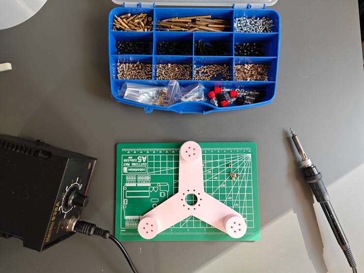
❗ Although all related 3D parts can be affixed via M3 screws after printing, plastic parts tend to loosen or break after a while due to friction and abrasion. Thus, I employed a well-known injection molding technique to make some connections more sturdy — M3 brass threaded inserts.
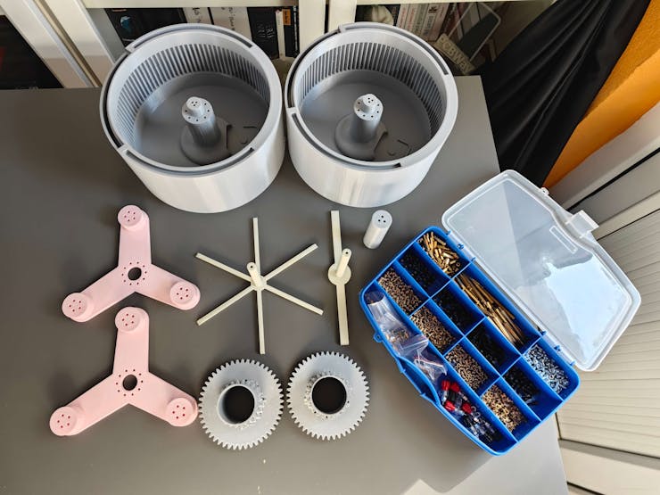
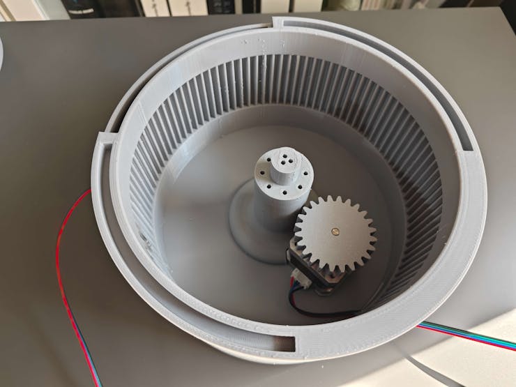
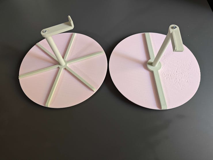
#️⃣ For each rotating platform, I fastened the required Nema 17 stepper motor and assembled the planetary gear mechanism consisting of a sun gear, three planet gears, a secondary stepper motor gear, and a Y-shaped planet carrier.
#️⃣ As explained earlier, I employed custom bearings to connect swiveling components to maintain stable torque distribution.
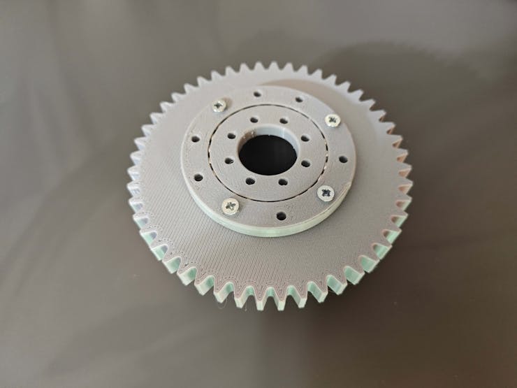
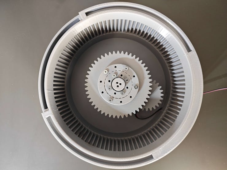
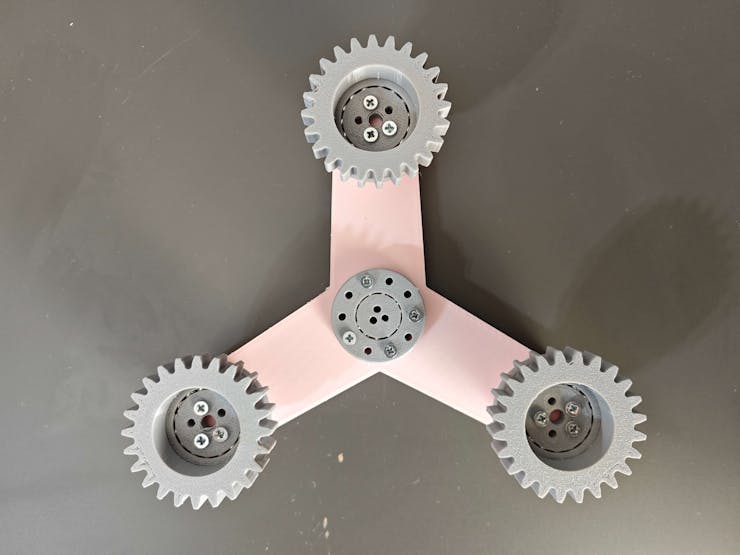
#️⃣ After completing the planetary gear mechanisms, I assembled the platform faces, face separators, and rotation pins respectively via M3 screws.
#️⃣ Then, I checked the straightness of the transportation road, bridging the first platform with the second platform.
#️⃣ I fastened the required Nema 17 stepper motors and assembled the transportation carrier consisting of two pinions, a pinion connection pin, a stepper motor direction gear, and a basic carrier arm.
#️⃣ As explained earlier, I employed custom bearings to connect swiveling components to maintain stable torque distribution.
#️⃣ Since the rack and pinion system has close-fitting components, I adjusted the tension of the M3 screws connecting the carrier components to reduce friction and stress.
#️⃣ After attaching the carrier arm, I fastened the micro switch via the hot glue gun to the left side of the transportation road, required for the automated homing sequence.
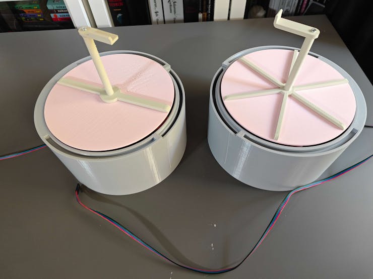
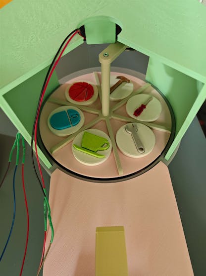
#️⃣ After completing the product transportation system, I assembled the platform roofs with their corresponding accessories.
#️⃣ As the selected homing methods, I fastened the IR break-beam sensor (receiver and transmitter) to the first platform roof and the micro switch to the second platform roof.

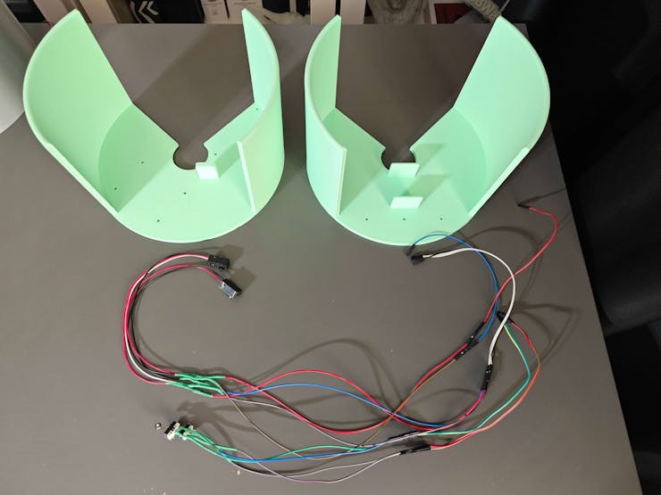
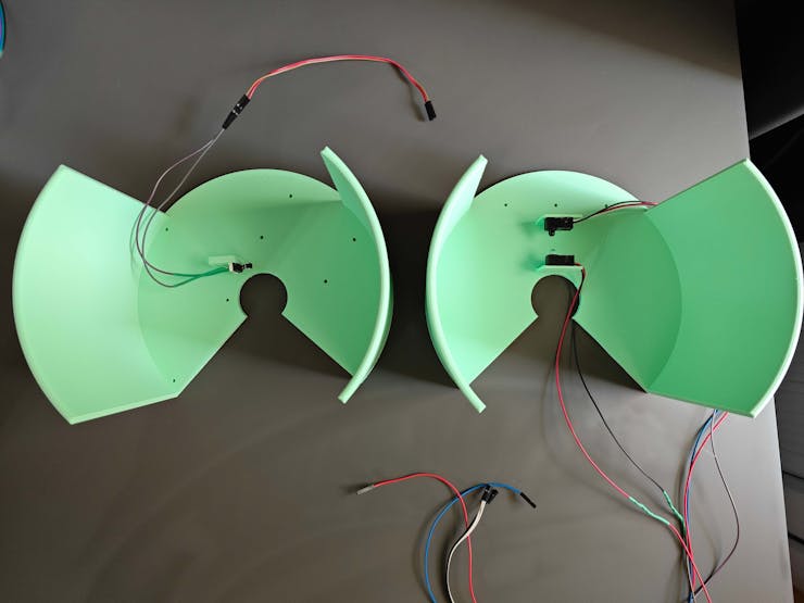
#️⃣ As I completed assembling all shipping workstation 3D parts, I attached Raspberry Pi 5, the USB webcam, and the tiny thermal printer to their corresponding add-ons.
#️⃣ Then, I fastened the Wall-E PCB to its encasement and finished all remaining PCB wiring, including the ATX adapter board 5V and 12V power outputs.

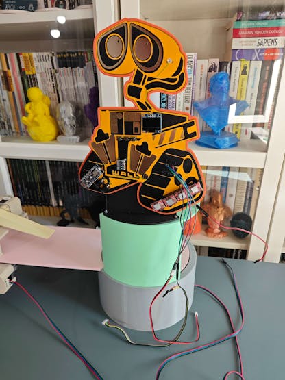

#️⃣ After affixing the Wall-E PCB successfully, I assembled all enamel pin-inspired sample products representing various objects by utilizing super glue.
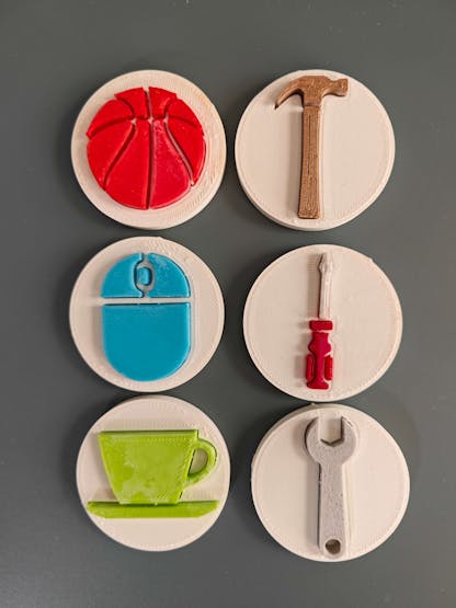
#️⃣ Then, I placed all sample products into their corresponding compartments on the first rotating platform, sectioned by the first face separator.

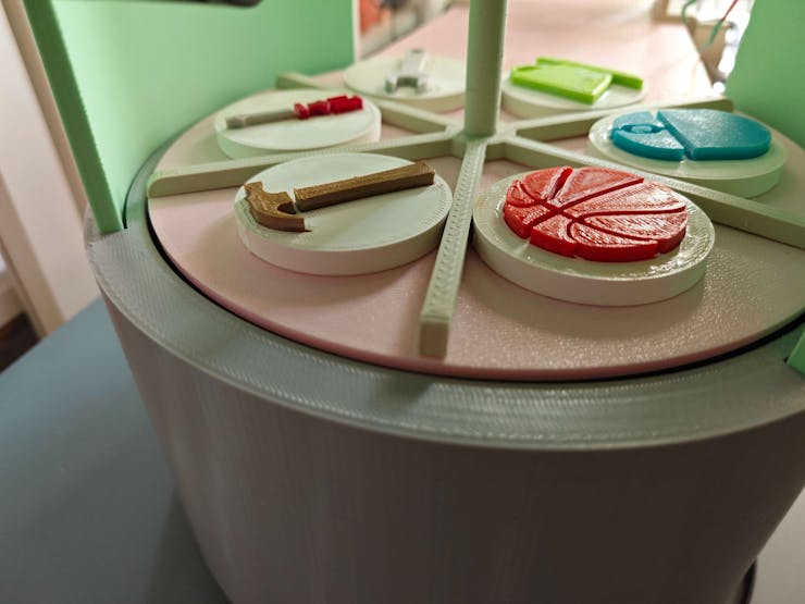
#️⃣ After preparing the enamel pin-inspired sample products, I rigorously analyzed the moving parts of the real-world shipping workstation to detect mechanical aberrations.

❗ After a while, I noticed the first iteration of the carrier arm with 35% infill engendered tension issues, resulting in sudden torque fluctuations. Thus, I printed the second iteration by reducing the carrier arm size and infill (12%).
Step 8.0: Setting up Arduino Nano Matter on Arduino IDE
Before proceeding with programming Arduino Nano Matter, I needed to configure the required board settings and install the associated component libraries.
Since Nano Matter is a state-of-the-art IoT development board with the powerful MGM240S wireless module from Silicon Labs providing versatile connectivity options, enabling Matter IoT protocol and Bluetooth® Low Energy, it requires Arduino IDE 2.0+ or Arduino Cloud Editor to be programmed.
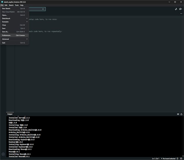
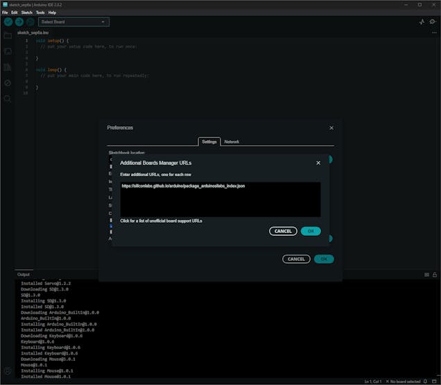
#️⃣ To enable the Silicon Labs core, go to File ➡ Preferences ➡ Additional boards manager URLs and add the official board package URL:
https://siliconlabs.github.io/arduino/package_arduinosilabs_index.json
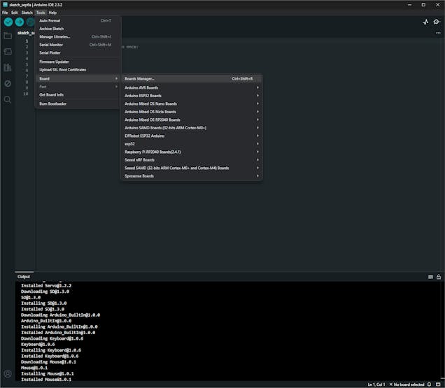
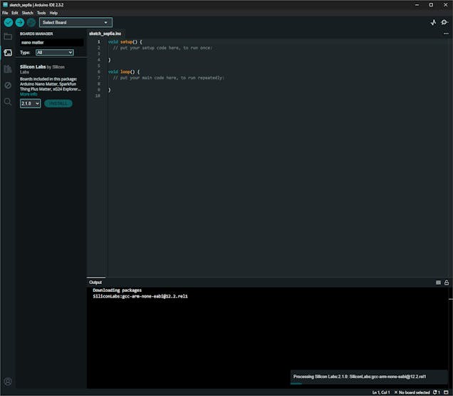
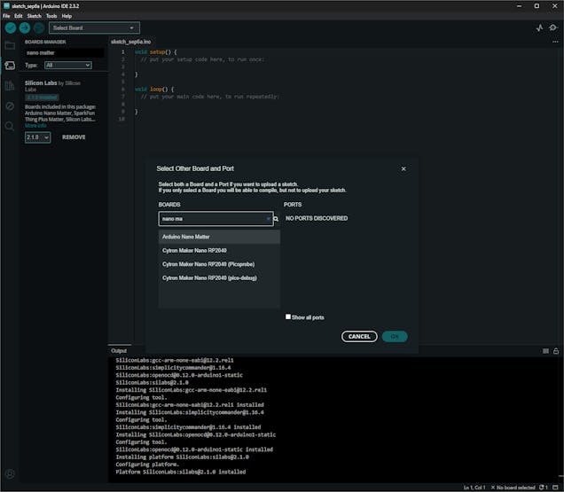
#️⃣ To install the required board core, navigate to Tools ➡ Board ➡ Boards Manager, search for Nano Matter, and download the latest version.
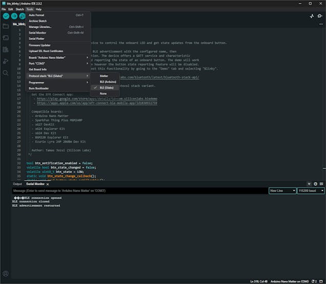
#️⃣ After installing the core successfully, choose Arduino Nano Matter to upload sketches. Then, navigate to Tools ➡ Protocol stack and select BLE (Silabs) to utilize the accurate configurations for establishing BLE connections.
#️⃣ After setting up Nano Matter, I installed the libraries required to control the attached electronic components:
Adafruit-Thermal-Printer-Library | Download
Adafruit_SSD1306 | Download
Adafruit-GFX-Library | Download
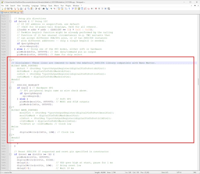
❗ As I started to program Nano Matter, the Arduino IDE threw some errors regarding the Adafruit SSD1306 library due to the functions incompatible with the Silicon Labs core, including but not limited to digitalPinToInterrupt and portOutputRegister. To solve these compiling issues, I modified the Adafruit_SSD1306.cpp file by removing the highlighted lines below.
Step 8: Programming Arduino Nano Matter to finalize the workstation control panel
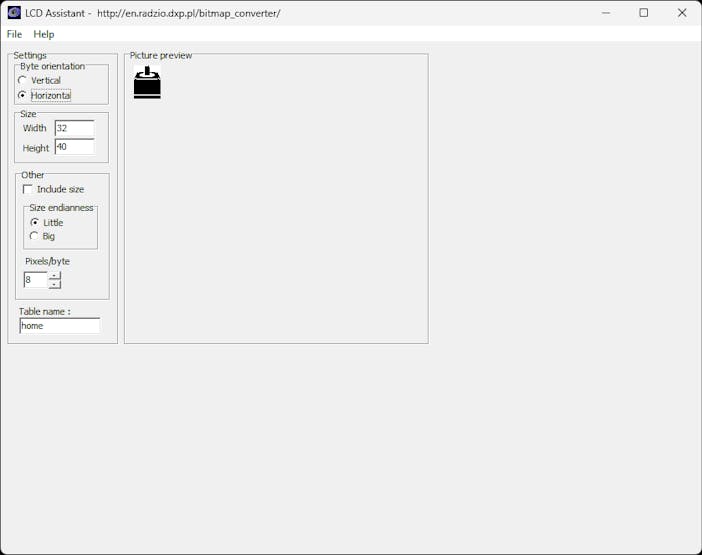
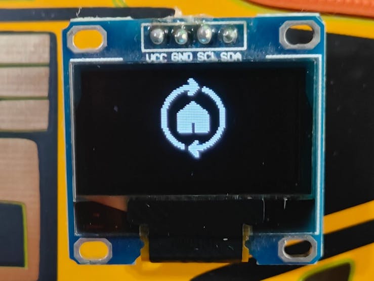
To prepare monochromatic images in order to display logos on the SSD1306 OLED screen and print bitmaps with the thermal printer, I followed the exact same process.
#️⃣ First, convert monochromatic bitmaps to compatible C data arrays by utilizing LCD Assistant.
#️⃣ Upload a monochromatic bitmap to LCD Assistant and select Vertical or Horizontal, depending on the screen type.
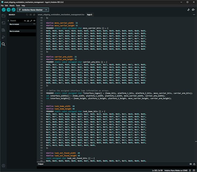
#️⃣ Then, create a header file (logo.h) to store all the converted C data arrays.
⭐ In the logo.h file, I defined multi-dimensional arrays to group the assigned logos and their sizes — width and height.
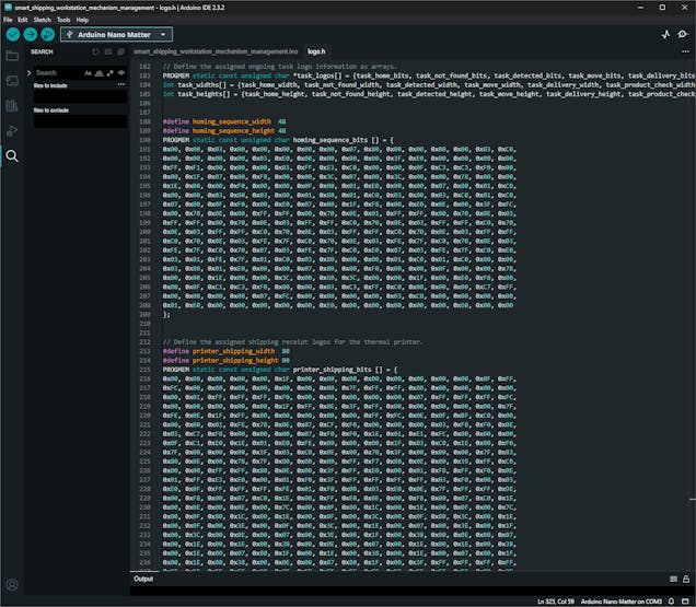
// Define the assigned ongoing task logo information as arrays.
PROGMEM static const unsigned char *task_logos[] = {task_home_bits, task_not_found_bits, task_detected_bits, task_move_bits, task_delivery_bits, task_product_check_bits};
int task_widths[] = {task_home_width, task_not_found_width, task_detected_width, task_move_width, task_delivery_width, task_product_check_width};
int task_heights[] = {task_home_height, task_not_found_height, task_detected_height, task_move_height, task_delivery_height, task_product_check_height};
#️⃣ Since I needed to assign unique UUID sets (128-bit) to BLE services and data characteristics individually, I employed this online UUID generator.
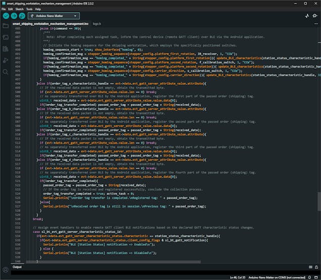
As explained in the previous steps, the workstation performs various features requiring interconnected networking and multiple development board integrations. Thus, the described code snippets represent the different aspects of the presented code file. Please refer to the actual code files to inspect functions thoroughly.
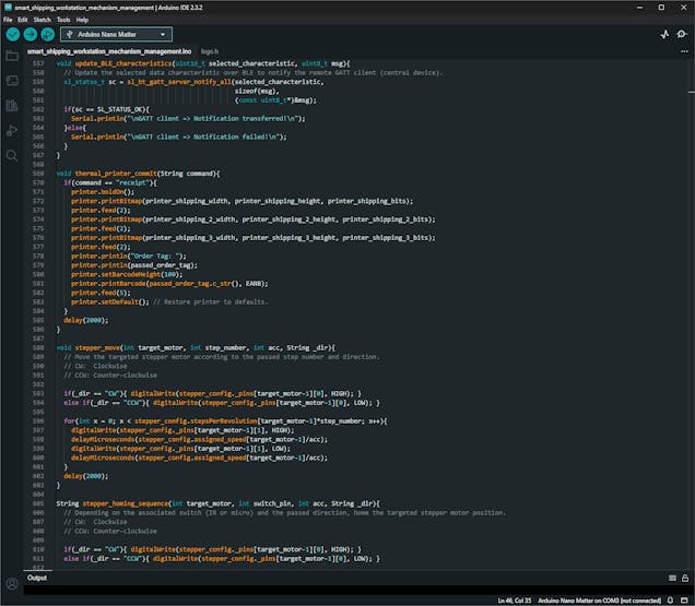
📁 smart_shipping_workstation_mechanism_management.ino
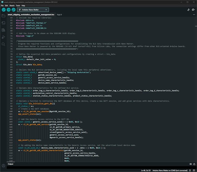
⭐ Include the required libraries.
#include <Wire.h>
#include "Adafruit_Thermal.h"
#include <Adafruit_GFX.h>
#include <Adafruit_SSD1306.h>
⭐ Import the logo.h file to obtain the converted C arrays.
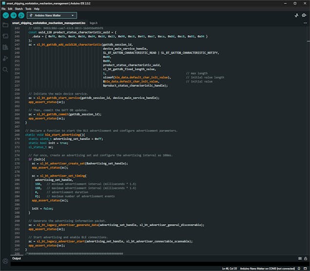
#include "logo.h"⭐ Declare the essential BLE service parameters and data characteristics.
⭐ Then, declare the ble_initialize_gatt_db function to initialize a GATT database, create a new GATT session, and add services with assigned data characteristics.
❗ As required by the Silicon Labs BLE protocol stack [BLE (Silabs)], while adding services with the assigned data characteristics, the associated UUID arrays must start with the least significant bit (LSB) from right to left (rightmost).
Service UUID: 9485c88d-cae7-43c6-9013-16d456e05bf6
0xf6, 0x5b, 0xe0, 0x56, 0xd4, 0x16, 0x13, 0x90, 0xc6, 0x43, 0xe7, 0xca, 0x8d, 0xc8, 0x85, 0x94
static void ble_initialize_gatt_db(){
sl_status_t sc;
// Create a new GATT database.
sc = sl_bt_gattdb_new_session(&gattdb_session_id);
app_assert_status(sc);
// Add the Generic Access service to the GATT DB.
const uint8_t generic_access_service_uuid[] = { 0x00, 0x18 };
sc = sl_bt_gattdb_add_service(gattdb_session_id,
sl_bt_gattdb_primary_service,
SL_BT_GATTDB_ADVERTISED_SERVICE,
sizeof(generic_access_service_uuid),
generic_access_service_uuid,
&generic_access_service_handle);
app_assert_status(sc);
// By adding the device name characteristic to the Generic Access service, set the advertised local device name.
const sl_bt_uuid_16_t device_name_characteristic_uuid = { .data = { 0x00, 0x2A } };
sc = sl_bt_gattdb_add_uuid16_characteristic(gattdb_session_id,
generic_access_service_handle,
SL_BT_GATTDB_CHARACTERISTIC_READ,
0x00,
0x00,
device_name_characteristic_uuid,
sl_bt_gattdb_fixed_length_value,
sizeof(advertised_device_name) - 1,
sizeof(advertised_device_name) - 1,
advertised_device_name,
&device_name_characteristic_handle);
app_assert_status(sc);
// Initiate the Generic Access service.
sc = sl_bt_gattdb_start_service(gattdb_session_id, generic_access_service_handle);
app_assert_status(sc);
/*
NOTE: As required by the Silicon Labs BLE protocol stack [BLE (Silabs)], to add services and data characteristics, the UUID arrays must start with the least significant bit (LSB) from left to right.
*/
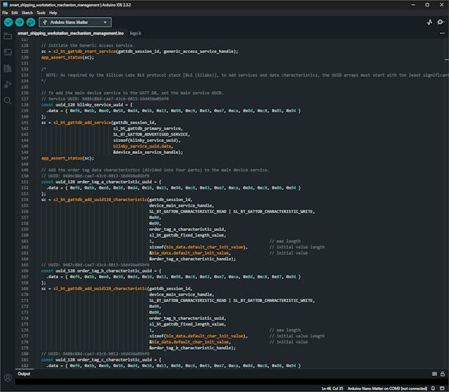
// To add the main device service to the GATT DB, set the main service UUID.
// Service UUID: 9485c88d-cae7-43c6-9013-16d456e05bf6
const uuid_128 blinky_service_uuid = {
.data = { 0xf6, 0x5b, 0xe0, 0x56, 0xd4, 0x16, 0x13, 0x90, 0xc6, 0x43, 0xe7, 0xca, 0x8d, 0xc8, 0x85, 0x94 }
};
sc = sl_bt_gattdb_add_service(gattdb_session_id,
sl_bt_gattdb_primary_service,
SL_BT_GATTDB_ADVERTISED_SERVICE,
sizeof(blinky_service_uuid),
blinky_service_uuid.data,
&device_main_service_handle);
app_assert_status(sc);
// Add the order tag data characteristics (divided into four parts) to the main device service.
// UUID: 9486c88d-cae7-43c6-9013-16d456e05bf6
const uuid_128 order_tag_a_characteristic_uuid = {
.data = { 0xf6, 0x5b, 0xe0, 0x56, 0xd4, 0x16, 0x13, 0x90, 0xc6, 0x43, 0xe7, 0xca, 0x8d, 0xc8, 0x86, 0x94 }
};
sc = sl_bt_gattdb_add_uuid128_characteristic(gattdb_session_id,
device_main_service_handle,
SL_BT_GATTDB_CHARACTERISTIC_READ | SL_BT_GATTDB_CHARACTERISTIC_WRITE,
0x00,
0x00,
order_tag_a_characteristic_uuid,
sl_bt_gattdb_fixed_length_value,
1, // max length
sizeof(ble_data.default_char_init_value), // initial value length
&ble_data.default_char_init_value, // initial value
&order_tag_a_characteristic_handle);
// UUID: 9487c88d-cae7-43c6-9013-16d456e05bf6
const uuid_128 order_tag_b_characteristic_uuid = {
.data = { 0xf6, 0x5b, 0xe0, 0x56, 0xd4, 0x16, 0x13, 0x90, 0xc6, 0x43, 0xe7, 0xca, 0x8d, 0xc8, 0x87, 0x94 }
};
sc = sl_bt_gattdb_add_uuid128_characteristic(gattdb_session_id,
device_main_service_handle,
SL_BT_GATTDB_CHARACTERISTIC_READ | SL_BT_GATTDB_CHARACTERISTIC_WRITE,
0x00,
0x00,
order_tag_b_characteristic_uuid,
sl_bt_gattdb_fixed_length_value,
1, // max length
sizeof(ble_data.default_char_init_value), // initial value length
&ble_data.default_char_init_value, // initial value
&order_tag_b_characteristic_handle);
// UUID: 9488c88d-cae7-43c6-9013-16d456e05bf6
const uuid_128 order_tag_c_characteristic_uuid = {
.data = { 0xf6, 0x5b, 0xe0, 0x56, 0xd4, 0x16, 0x13, 0x90, 0xc6, 0x43, 0xe7, 0xca, 0x8d, 0xc8, 0x88, 0x94 }
};
sc = sl_bt_gattdb_add_uuid128_characteristic(gattdb_session_id,
device_main_service_handle,
SL_BT_GATTDB_CHARACTERISTIC_READ | SL_BT_GATTDB_CHARACTERISTIC_WRITE,
0x00,
0x00,
order_tag_c_characteristic_uuid,
sl_bt_gattdb_fixed_length_value,
1, // max length
sizeof(ble_data.default_char_init_value), // initial value length
&ble_data.default_char_init_value, // initial value
&order_tag_c_characteristic_handle);
// UUID: 9489c88d-cae7-43c6-9013-16d456e05bf6
const uuid_128 order_tag_d_characteristic_uuid = {
.data = { 0xf6, 0x5b, 0xe0, 0x56, 0xd4, 0x16, 0x13, 0x90, 0xc6, 0x43, 0xe7, 0xca, 0x8d, 0xc8, 0x89, 0x94 }
};
sc = sl_bt_gattdb_add_uuid128_characteristic(gattdb_session_id,
device_main_service_handle,
SL_BT_GATTDB_CHARACTERISTIC_READ | SL_BT_GATTDB_CHARACTERISTIC_WRITE,
0x00,
0x00,
order_tag_d_characteristic_uuid,
sl_bt_gattdb_fixed_length_value,
1, // max length
sizeof(ble_data.default_char_init_value), // initial value length
&ble_data.default_char_init_value, // initial value
&order_tag_d_characteristic_handle);
// Add the workstation control characteristic to the main device service.
// UUID: 9490c88d-cae7-43c6-9013-16d456e05bf6
const uuid_128 workstation_control_characteristic_uuid = {
.data = { 0xf6, 0x5b, 0xe0, 0x56, 0xd4, 0x16, 0x13, 0x90, 0xc6, 0x43, 0xe7, 0xca, 0x8d, 0xc8, 0x90, 0x94 }
};
sc = sl_bt_gattdb_add_uuid128_characteristic(gattdb_session_id,
device_main_service_handle,
SL_BT_GATTDB_CHARACTERISTIC_READ | SL_BT_GATTDB_CHARACTERISTIC_WRITE,
0x00,
0x00,
workstation_control_characteristic_uuid,
sl_bt_gattdb_fixed_length_value,
1, // max length
sizeof(ble_data.default_char_init_value), // initial value length
&ble_data.default_char_init_value, // initial value
&workstation_control_characteristic_handle);
// Add the station status and product characteristics to the main device service to notify the remote GATT client (central device) over BLE.
// UUID: 9491c88d-cae7-43c6-9013-16d456e05bf6
const uuid_128 station_status_characteristic_uuid = {
.data = { 0xf6, 0x5b, 0xe0, 0x56, 0xd4, 0x16, 0x13, 0x90, 0xc6, 0x43, 0xe7, 0xca, 0x8d, 0xc8, 0x91, 0x94 }
};
sc = sl_bt_gattdb_add_uuid128_characteristic(gattdb_session_id,
device_main_service_handle,
SL_BT_GATTDB_CHARACTERISTIC_READ | SL_BT_GATTDB_CHARACTERISTIC_NOTIFY,
0x00,
0x00,
station_status_characteristic_uuid,
sl_bt_gattdb_fixed_length_value,
1, // max length
sizeof(ble_data.default_char_init_value), // initial value length
&ble_data.default_char_init_value, // initial value
&station_status_characteristic_handle);
// UUID: 9492c88d-cae7-43c6-9013-16d456e05bf6
const uuid_128 product_status_characteristic_uuid = {
.data = { 0xf6, 0x5b, 0xe0, 0x56, 0xd4, 0x16, 0x13, 0x90, 0xc6, 0x43, 0xe7, 0xca, 0x8d, 0xc8, 0x92, 0x94 }
};
sc = sl_bt_gattdb_add_uuid128_characteristic(gattdb_session_id,
device_main_service_handle,
SL_BT_GATTDB_CHARACTERISTIC_READ | SL_BT_GATTDB_CHARACTERISTIC_NOTIFY,
0x00,
0x00,
product_status_characteristic_uuid,
sl_bt_gattdb_fixed_length_value,
1, // max length
sizeof(ble_data.default_char_init_value), // initial value length
&ble_data.default_char_init_value, // initial value
&product_status_characteristic_handle);
// Initiate the main device service.
sc = sl_bt_gattdb_start_service(gattdb_session_id, device_main_service_handle);
app_assert_status(sc);
// Then, commit the GATT DB updates.
sc = sl_bt_gattdb_commit(gattdb_session_id);
app_assert_status(sc);
}⭐ Declare the ble_start_advertising function to enable the BLE advertisement and configure advertisement parameters.
static void ble_start_advertising(){
  static uint8_t advertising_set_handle = 0xff;
  static bool init = true;
  sl_status_t sc;

  // For once, create an advertising set and configure the advertising interval as 100ms.
  if (init){
    sc = sl_bt_advertiser_create_set(&advertising_set_handle);
    app_assert_status(sc);

    sc = sl_bt_advertiser_set_timing(
      advertising_set_handle,
      160,   // minimum advertisement interval (milliseconds * 1.6)
      160,   // maximum advertisement interval (milliseconds * 1.6)
      0,     // advertisement duration
      0);    // maximum number of advertisement events
    app_assert_status(sc);

    init = false;
  }

  // Generate the advertising information packet.
  sc = sl_bt_legacy_advertiser_generate_data(advertising_set_handle, sl_bt_advertiser_general_discoverable);
  app_assert_status(sc);

  // Start advertising and enable BLE connections.
  sc = sl_bt_legacy_advertiser_start(advertising_set_handle, sl_bt_advertiser_connectable_scannable);
  app_assert_status(sc);
}
⭐ Define the thermal printer object for passing commands through the hardware serial port of Nano Matter — Serial1.
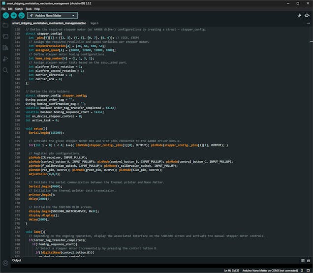
Adafruit_Thermal printer(&Serial1);⭐ Define the required Nema 17 stepper motor (attached to A4988 driver modules) configurations by creating a struct — stepper_config — so as to assign and call variables per stepper motor efficiently.
struct stepper_config{
  int _pins[4][2] = {{2, 3}, {4, 5}, {6, 7}, {8, 9}}; // (DIR, STEP)
  // Assign the required revolution and speed variables per stepper motor.
  int stepsPerRevolution[4] = {36, 64, 100, 50};
  int assigned_speed[4] = {16000, 12000, 12000, 1000};
  // Define stepper motor homing configurations.
  int home_step_number[4] = {1, 1, 3, 1};
  // Assign stepper motor tasks based on the associated part.
  int platform_first_rotation = 1;
  int platform_second_rotation = 2;
  int carrier_direction = 3;
  int carrier_arm = 4;
};
🤖 After declaring fundamental variables and configurations, I started to program all the workstation control panel features showcased in the following steps. You can view the code files on GitHub with thorough commentary.
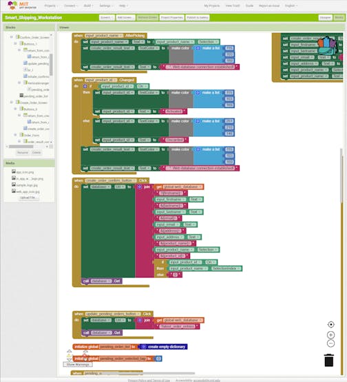
Step 9: Developing the mobile (Android) workstation application w/ MIT APP Inventor
To capitalize on the reliable BLE connectivity enabled by Nano Matter, I decided to develop a mobile workstation application (Android) operating as the workstation interface. Thanks to the Wi-Fi connectivity natively provided by a smartphone, the mobile application also works as the proxy between the workstation control panel (based on Nano Matter) and the web workstation application.
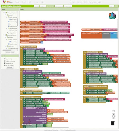
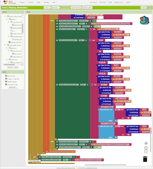
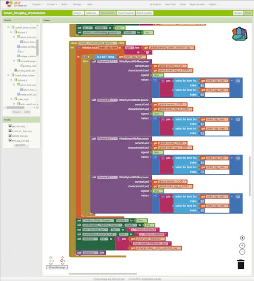
Since I am familiar with MIT App Inventor's syntax and structure for programming Android applications, I decided to develop my mobile application with MIT App Inventor, which is an intuitive visual programming environment that allows developers to build fully functional applications.
Since this mobile application is open-source, you can download its APK file below to test the available features on a compatible smartphone. Unfortunately, since MIT App Inventor employs a blocks-based (drag-and-drop) tool to facilitate programming, I cannot provide a code file for the mobile application. Nonetheless, MIT App Inventor lets developers review or modify applications by importing project files in the AIA format.
Thus, you can inspect my mobile application design and programming process by opening this application's AIA file on your account.
#️⃣ First, create an MIT App Inventor account.
#️⃣ After downloading the project's AIA file (Smart_Shipping_Workstation.aia), import it into your account.
❗ Since MIT App Inventor does not provide functions for BLE data transmission natively, I utilized the latest version of the BluetoothLE extension to enable BLE connectivity for my mobile application. In this tutorial, you can get more information about the extension features.
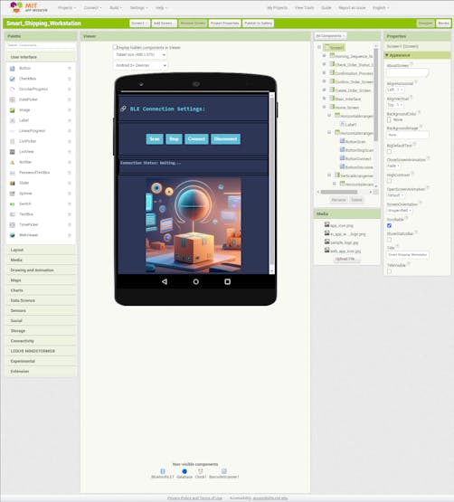
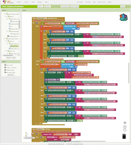
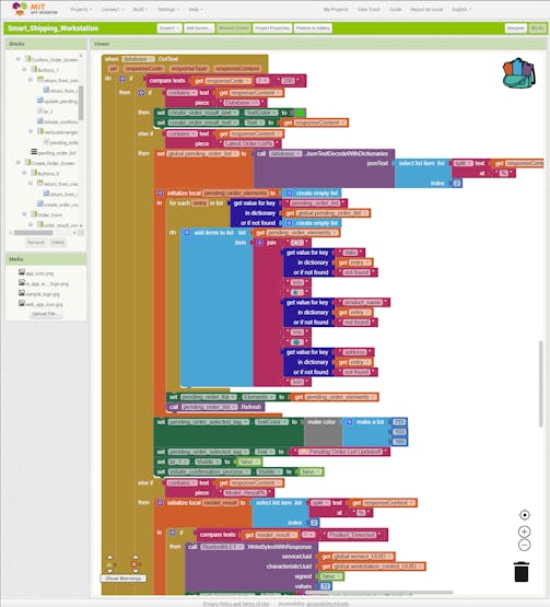
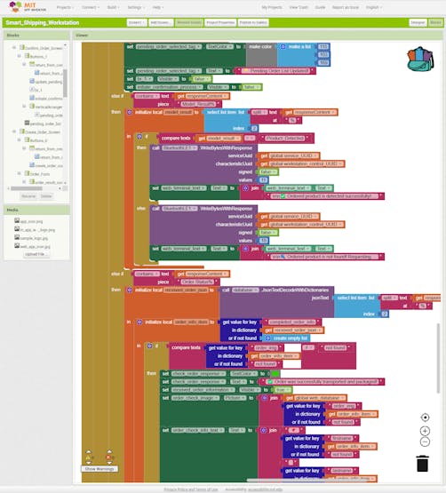
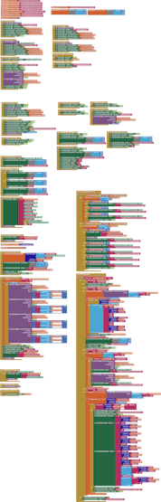
#️⃣ After importing the project's AIA file, you can review or modify my coding blocks via the Blocks editor.
In the following steps, I will elucidate all of the accessible features of this mobile application.
After installing my mobile application on a compatible Android smartphone, I did not encounter any connectivity or data transmission problems while running the available features.


Step 10: Developing the web workstation application on Raspberry Pi 5
As discussed earlier, I decided to develop a versatile web application to manage the MariaDB database server hosted by Raspberry Pi 5, run the Edge Impulse FOMO object detection model, and transfer the detection results with the modified model resulting images.
Since I had already set up the essential firmware to develop the web application, I immediately started to configure the required web application settings on Raspberry Pi 5.
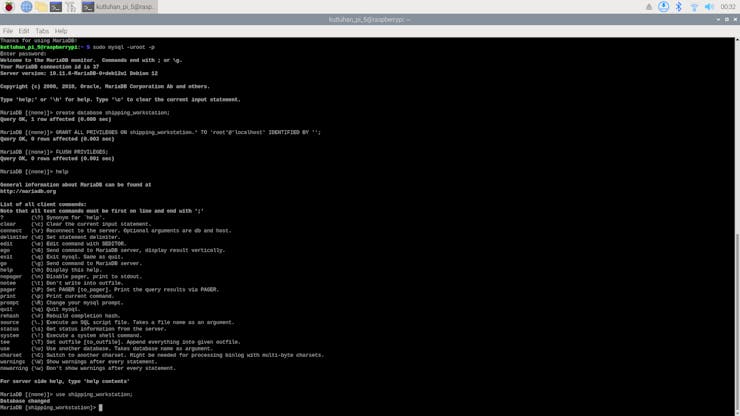
#️⃣ First, I created a new MariaDB database named shipping_workstation by utilizing the integrated terminal prompt.
sudo mysql -uroot -p
create database shipping_workstation;
GRANT ALL PRIVILEGES ON shipping_workstation.* TO 'root'@'localhost' IDENTIFIED BY '';
FLUSH PRIVILEGES;
#️⃣ Then, I created a database table (orders) with the required data fields under the new database.
use shipping_workstation;
CREATE TABLE `orders`( id int AUTO_INCREMENT PRIMARY KEY, `date` varchar(255), firstname varchar(255), lastname varchar(255), email varchar(255), address varchar(255), product_name varchar(255), product_id int, order_tag int, order_img varchar(255), order_status varchar(255) );
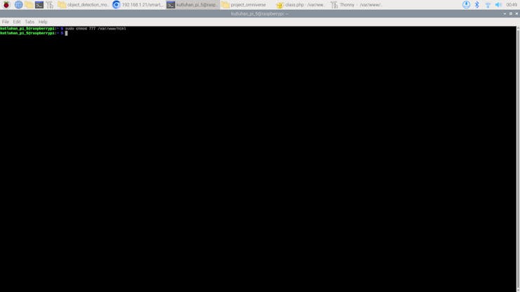
#️⃣ Since the application folders and files under the root folder of the Apache server are restricted, I changed permissions to enable file creation and modification while running the web application.
sudo chmod 777 /var/www/html
After setting up the mentioned web application configurations, I started to program the application features on Raspberry Pi 5.
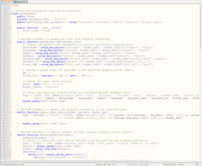
📁 class.php
⭐ To bundle all functions under a specific structure, declare the workstation class.
⭐ In the append_new_order function:
⭐ Check the array keys of the passed order information to register an accurate shipping entry.
⭐ Generate a unique order tag (barcode) number — EAN-8.
⭐ Then, insert the generated shipping entry with the entry creation date into the given MariaDB database table.
public function append_new_order($order_info){
// Inspect the passed order information to register an accurate shipping entry.
$firstname = array_key_exists("firstname", $order_info) ? $order_info["firstname"] : "empty";
$lastname = array_key_exists("lastname", $order_info) ? $order_info["lastname"] : "empty";
$email = array_key_exists("email", $order_info) ? $order_info["email"] : "empty";
$address = array_key_exists("address", $order_info) ? $order_info["address"] : "empty";
$product_name = array_key_exists("product_name", $order_info) ? $order_info["product_name"] : "empty";
$product_id = array_key_exists("product_id", $order_info) ? $order_info["product_id"] : -1;
$order_img = array_key_exists("order_img", $order_info) ? $order_info["order_img"] : "empty";
// Assign a unique order tag (barcode) to the generated shipping entry — EAN-8.
$N = 8;
$order_tag = rand(pow(10, $N-1), (pow(10, $N)-1));
// Update the order status and date.
$date = date("Y/m/d__h:i:s");
$order_status = "created";
// Insert the generated shipping entry into the given MariaDB database table.
$sql = "INSERT INTO `$this->database_table` (`date`, `firstname`, `lastname`, `email`, `address`, `product_name`, `product_id`, `order_img`, `order_tag`, `order_status`)
VALUES ('$date', '$firstname', '$lastname', '$email', '$address', '$product_name', '$product_id', '$order_img', '$order_tag', '$order_status')";
mysqli_query($this->conn, $sql);
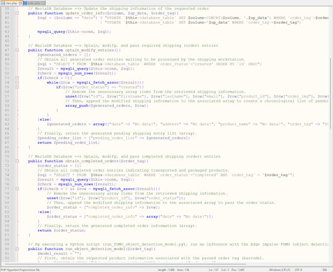
}⭐ In the update_order_info function, update the given column (data field) with the passed information. If the given data field is date, concatenate the new and older dates.
public function update_order_info($column, $up_data, $order_tag){
		$sql = ($column == "date") ? "UPDATE `$this->database_table` SET $column=CONCAT($column, ',$up_data') WHERE `order_tag`=$order_tag"
		                           : "UPDATE `$this->database_table` SET $column='$up_data' WHERE `order_tag`=$order_tag";

		mysqli_query($this->conn, $sql);
	}
⭐ In the obtain_completed_orders function:
⭐ Obtain all completed order entries indicating transported and packaged products.
⭐ Remove the unnecessary array items from the retrieved shipping information.
⭐ Append the modified shipping information array to the associated multidimensional array.
⭐ Then, return the generated multidimensional array.
public function obtain_completed_orders($order_tag){
$order_status = [];
// Obtain all completed order entries indicating transported and packaged products.
$sql = "SELECT * FROM `$this->database_table` WHERE `order_status`='completed' AND `order_tag` = '$order_tag'";
$result = mysqli_query($this->conn, $sql);
$check = mysqli_num_rows($result);
if($check > 0 && $row = mysqli_fetch_assoc($result)){
// Remove the unnecessary array items from the retrieved shipping information.
unset($row["id"], $row["product_id"], $row["order_status"]);
// Then, append the modified shipping information to the associated array to pass the order status.
$order_status = ["completed_order_info" => $row];
}else{
$order_status = ["completed_order_info" => array("date" => "No data!")];
}
// Finally, return the generated completed order information (array).
return $order_status;
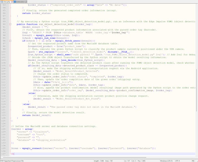
}⭐ In the run_object_detection_model function:
⭐ Obtain the requested product information associated with the passed order tag (barcode).
⭐ Then, execute the given Python script to run an inference with the Edge Impulse FOMO object detection model to classify the sample product currently positioned under the USB webcam connected to Raspberry Pi 5.
⭐ Decode the JSON object transferred by the Python script to obtain the model resulting information.
⭐ As the Python script transfers the detected product class after running the FOMO object detection model:
⭐ If the ordered product is successfully found, enable the product transportation procedure and change the order status to completed. Then, append the order completion date and the path of the model resulting image generated by the Python script to the associated database entry.
⭐ Otherwise, enable the first rotating platform position change procedure.
❗ Since the web application executes the given Python script via the shell_exec function, it is not possible to observe debugging errors instantly like using the terminal. Thus, I appended 2>&1 to the command line in the shell_exec function to display debugging errors on the browser directly. In this regard, I was able to develop the web application way faster.
public function run_object_detection_model($order_tag){
$model_result = "";
// First, obtain the requested product information associated with the passed order tag (barcode).
$sql = "SELECT * FROM `$this->database_table` WHERE `order_tag`='$order_tag'";
$result = mysqli_query($this->conn, $sql);
$check = mysqli_num_rows($result);
if($check > 0 && $row = mysqli_fetch_assoc($result)){
// Get the requested product name from the MariaDB database table.
$requested_product = $row["product_name"];
// Then, execute the given Python script to classify the product sample currently positioned under the USB camera.
$path = str_replace("/assets", "/object_detection_model", dirname(__FILE__));
$run_Python_script = shell_exec('sudo python3 "'.$path.'/run_FOMO_object_detection_model.py" 2>&1'); // Add 2>&1 for debugging errors directly on the browser.
// Decode the JSON object transferred by the Python script to obtain the model resulting information.
$model_resulting_data = json_decode($run_Python_script);
// As the Python script transfers the detected product class after running the FOMO object detection model, check whether the ordered product was successfully found.
if($model_resulting_data->detected_product_class == $requested_product){
// If so, make the shipping workstation transportation request via the Android application.
$model_result = "Model_Result%Product_Detected";
// Change the order status to completed.
$this->update_order_info("order_status", "completed", $order_tag);
// Then, update the order completion date of the given order (shipping) entry.
$date = date("Y/m/d__h:i:s");
$this->update_order_info("date", $date, $order_tag);
// Also, append the product confirmation (model resulting) image path generated by the Python script to the order entry.
$this->update_order_info("order_img", $model_resulting_data->product_confirmation_image, $order_tag);
}else{
// Otherwise, make the shipping workstation current product position change request.
$model_result = "Model_Result%Product_Not_Found";
}
}else{
$model_result = "The passed order tag does not exist in the MariaDB database.";
}
// Finally, return the model detection result.
return $model_result;
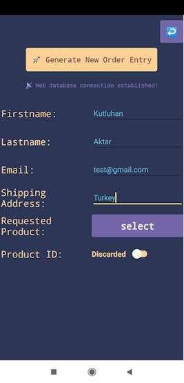
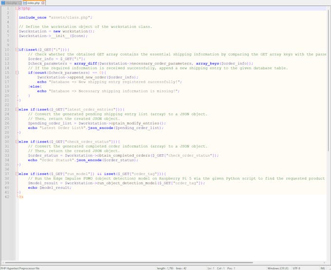
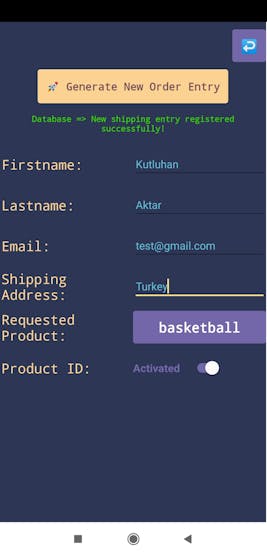
}📁 Index.php
⭐ Check whether the obtained GET array contains the essential shipping information by comparing the GET array keys with the required data fields.
.../?i[firstname]=Kutluhan&i[lastname]=Aktar&i[email]=test@gmail.com&i[address]=Turkey&i[product_name]=wrench&i[product_id]=0
⭐ If the required information is received successfully, append a new shipping entry to the given MariaDB database table.
if(isset($_GET["i"])){
	// Check whether the obtained GET array contains the essential shipping information by comparing the GET array keys with the passed parameter names.
	$order_info = $_GET["i"];
	$check_parameters = array_diff($workstation->necessary_order_parameters, array_keys($order_info));
	// If the required information is received successfully, append a new shipping entry to the given database table.
	if(count($check_parameters) == 0){
		$workstation->append_new_order($order_info);
		echo "Database => New shipping entry registered successfully!";
	}else{
		echo "Database => Necessary shipping information is missing!";
	}
}
⭐ Run the Edge Impulse FOMO object detection model by executing the given Python script to find the requested product associated with the passed order tag.
else if(isset($_GET["run_model"]) && isset($_GET["order_tag"])){
	// Run the Edge Impulse FOMO (object detection) model on Raspberry Pi 5 via the given Python script to find the requested product associated with the passed order tag.
	$model_result = $workstation->run_object_detection_model($_GET["order_tag"]);
	echo $model_result;
}
🤖 To review the programming of the web application features showcased in the following steps, you can inspect the code files on GitHub with thorough commentary.
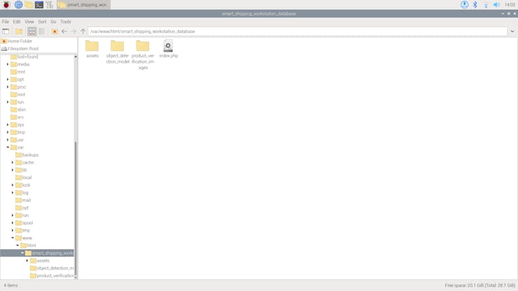
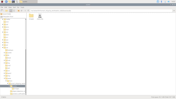
📁 Complete web application syntax:
- /assets
- /images
- class.php
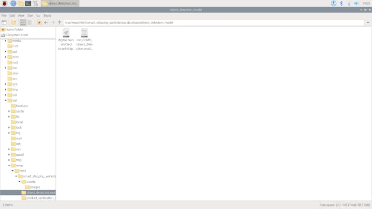
- /object_detection_model
- digital-twin-enabled-smart-shipping-workstation-linux-aarch64-v2.eim
- run_FOMO_object_detection_model.py
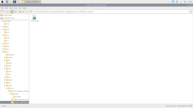
- /product_verification_images
- default.jpg
- index.php
Step 10.1: Setting up the FOMO object detection model on Raspberry Pi 5
While programming the web application, I needed to configure some settings on Raspberry Pi 5 to run the Edge Impulse FOMO object detection model successfully.
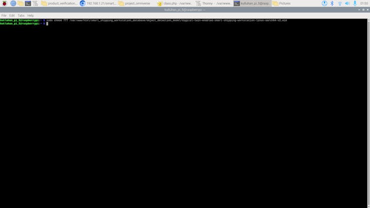
#️⃣ First, I changed the file permissions of the model file — Linux (AARCH64) application (.eim) — via the terminal to make it executable.
sudo chmod 777 /var/www/html/smart_shipping_workstation_database/object_detection_model/digital-twin-enabled-smart-shipping-workstation-linux-aarch64-v2.eim
Even after changing the permissions, the web application cannot access some Raspberry Pi 5 features requiring the root user (super-user) privileges while executing Python scripts, such as accessing frames captured by the attached USB webcam.
Although assigning super-user privileges to different users is a security risk, I decided to give the web application the ability to execute commands with root user privileges. In this case, it was applicable since the installed Apache server is only operating as a local development environment.
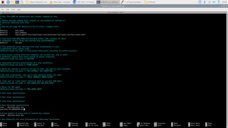
#️⃣ To change user privileges, open the sudoers file and alter it safely on the terminal.
sudo visudo
#️⃣ Since the Apache server employs www-data as the user name while accessing features, add these lines to the end of the sudoers file to enable the web application with root user privileges.
www-data ALL=NOPASSWD:ALL

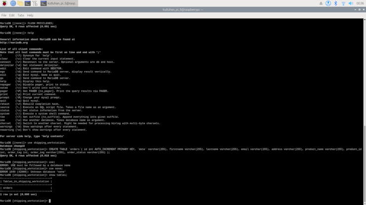
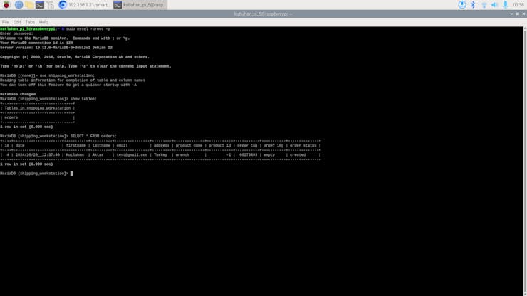
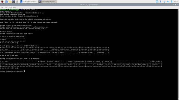
#️⃣ After running the FOMO model successfully, I checked whether the web application saves the model results generated by the Python script to the given MariaDB database table successfully via the MariaDB prompt on the terminal.
show tables;
Step 10.2: Running the configured model via the Python SDK
#️⃣ First, install the pre-built OpenCV Python package.
❗ If you do not run a virtual environment on Pi 5, the system may throw an error while trying to install packages via pip. To simply solve this issue, you can add --break-system-packages.
sudo pip3 install opencv-contrib-python --break-system-packages
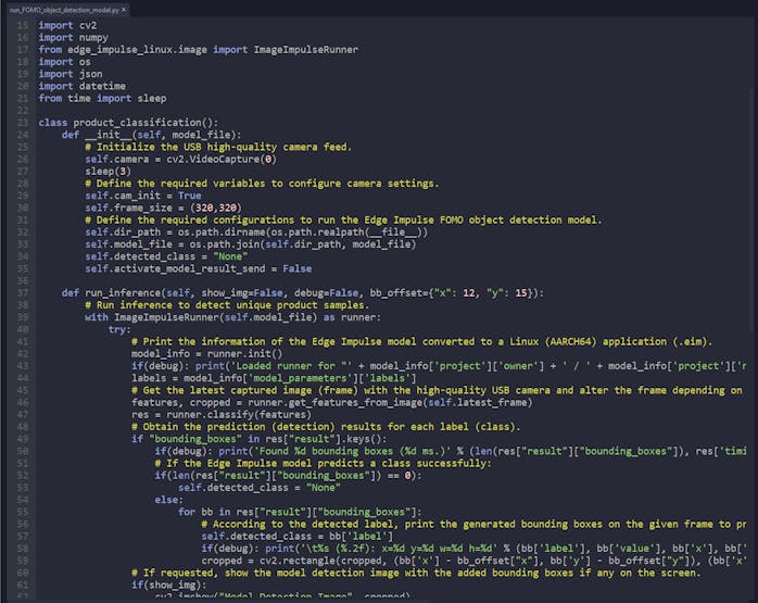
📁 run_FOMO_object_detection_model.py
⭐ Include the required modules.
import cv2
import numpy
from edge_impulse_linux.image import ImageImpulseRunner
import os
import json
import datetime
from time import sleep
⭐ To bundle all functions under a specific structure, declare the product_classification class.
⭐ In the __init__ function, initiate the high-quality USB webcam feed and declare the required variables.
def __init__(self, model_file):
# Initialize the USB high-quality camera feed.
self.camera = cv2.VideoCapture(0)
sleep(3)
# Define the required variables to configure camera settings.
self.cam_init = True
self.frame_size = (320,320)
# Define the required configurations to run the Edge Impulse FOMO object detection model.
self.dir_path = os.path.dirname(os.path.realpath(__file__))
self.model_file = os.path.join(self.dir_path, model_file)
self.detected_class = "None"
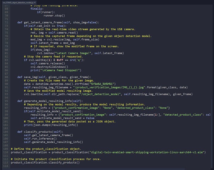
self.activate_model_result_send = False⭐ In the run_inference function:
⭐ Get the latest frame captured by the high-quality USB webcam and transform the frame depending on the given model configurations.
⭐ Run an inference with the Edge Impulse FOMO object detection model to obtain the prediction (detection) results.
⭐ According to the detected label and generated bounding box coordinates, draw the bounding box with specified offsets on the passed frame to produce the model resulting image.
⭐ Then, save the produced model resulting image and enable data transfer for model results.
def run_inference(self, show_img=False, debug=False, bb_offset={"x": 12, "y": 15}):
        # Run inference to detect unique product samples.
        with ImageImpulseRunner(self.model_file) as runner:
            try:
                # Print the information of the Edge Impulse model converted to a Linux (AARCH64) application (.eim).
                model_info = runner.init()
                if(debug): print('Loaded runner for "' + model_info['project']['owner'] + ' / ' + model_info['project']['name'] + '"')
                labels = model_info['model_parameters']['labels']
                # Get the latest captured image (frame) with the high-quality USB camera and alter the frame depending on the given model so as to run an inference.
                features, cropped = runner.get_features_from_image(self.latest_frame)
                res = runner.classify(features)
                # Obtain the prediction (detection) results for each label (class).
                if "bounding_boxes" in res["result"].keys():
                    if(debug): print('Found %d bounding boxes (%d ms.)' % (len(res["result"]["bounding_boxes"]), res['timing']['dsp'] + res['timing']['classification']))
                    # If the Edge Impulse model predicts a class successfully:
                    if(len(res["result"]["bounding_boxes"]) == 0):
                        self.detected_class = "None"
                    else:
                        for bb in res["result"]["bounding_boxes"]:
                            # According to the detected label, print the generated bounding boxes on the given frame to produce the model resulting image.
                            self.detected_class = bb['label']
                            if(debug): print('\t%s (%.2f): x=%d y=%d w=%d h=%d' % (bb['label'], bb['value'], bb['x'], bb['y'], bb['width'], bb['height']))
                            cropped = cv2.rectangle(cropped, (bb['x'] - bb_offset["x"], bb['y'] - bb_offset["y"]), (bb['x'] + bb['width'] + bb_offset["x"], bb['y'] + bb['height'] + bb_offset["y"]), (255, 0, 255), 3)
                # If requested, show the model detection image with the added bounding boxes if any on the screen.
                if(show_img):
                    cv2.imshow("Model Detection Image", cropped)
                # As detecting a class successfully, save the produced model resulting image and activate the model resulting data transfer.
                if(self.detected_class != "None"):
                    self.save_img(self.detected_class, cropped)
                    self.activate_model_result_send = True
            # Stop the running inference.
            finally:
                if(runner):
                    runner.stop()
⭐ In the generate_model_resulting_info function, produce the model resulting information and pass the generated data packet as a JSON object.
def generate_model_resulting_info(self):
        # Depending on the model results, produce the model resulting information.
        resulting_info = {"product_confirmation_image": "None", "detected_product_class": "None"}
        if(self.activate_model_result_send):
            resulting_info = {"product_confirmation_image": self.resulting_img_filename[1:], "detected_product_class": self.detected_class}
            self.activate_model_result_send = False
        # Then, pass the generated data packet as a JSON object.
        print(json.dumps(resulting_info))
🤖 For further inspection, you can review this code file on GitHub with thorough commentary.
Final Step: Conducting experiments with the real-world shipping workstation to validate and showcase all interconnected features
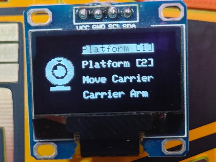
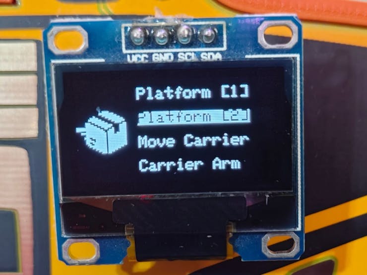
🚚📦📲 The shipping workstation control panel (Wall-E PCB) allows the user to calibrate each Nema 17 stepper motor position via the control buttons:
- Control Button [B] ➡️ Select
- Control Button [A] ➡️ Move Clockwise
- Control Button [C] ➡️ Move Counter-clockwise
🚚📦📲 While calibrating positions, the workstation control panel turns the RGB LED to white.
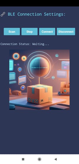
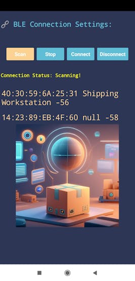
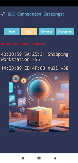
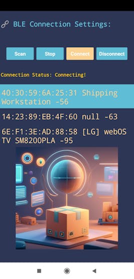
🚚📦📲 The mobile workstation application (Android-compatible) enables the user to establish a BLE connection with the workstation control panel through Nano Matter.
🚚📦📲 After establishing a successful BLE connection, the mobile application gives the user permission to access the workstation interface.
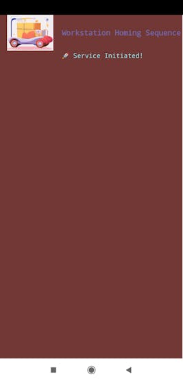
🚚📦📲 If the user activates the automated homing sequence, the mobile application communicates with the workstation control panel to initiate the sequence in accordance with the selected homing methods:
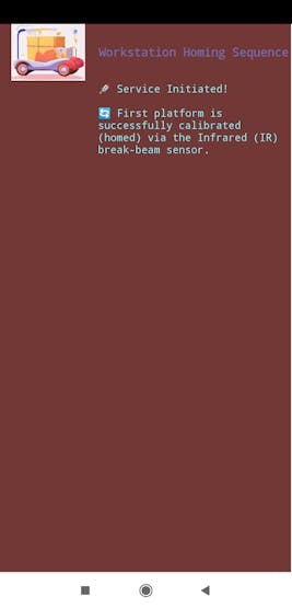
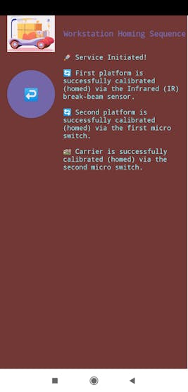
🚚📦📲 The first rotating platform utilizes the IR break-beam sensor to synchronize the 200-step per rotation pattern for 60° turns via its specified rotation pin.
🚚📦📲 The second rotating platform utilizes the first micro switch to align the face separator toward the transportation road via its specified rotation pin.
🚚📦📲 The transportation carrier employs the second micro switch to position itself near the center of the transportation road.
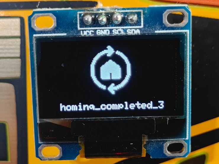
🚚📦📲 The workstation control panel turns the RGB LED to green while performing the homing sequence and notifies the user of the sequence progress on the SSD1306 display.
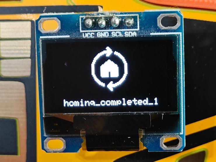
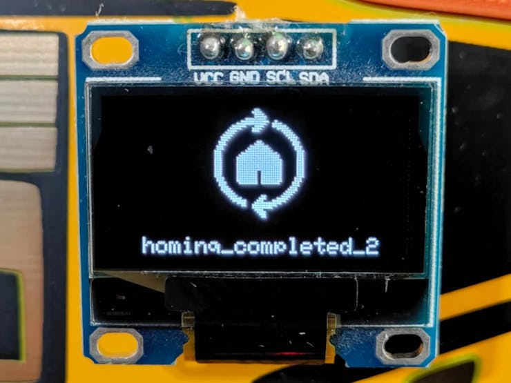

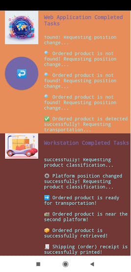
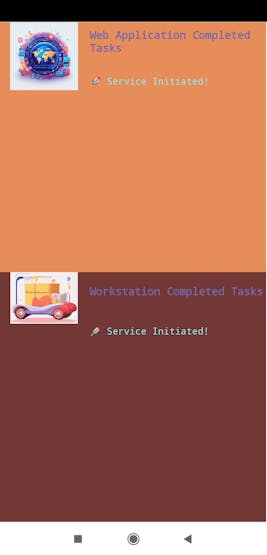
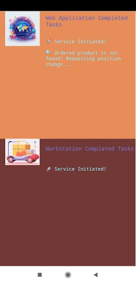
🚚📦📲 Since the control panel and the mobile application exchange data packets continuously as the homing sequence continues, the mobile application informs the user of each completed task via the dedicated terminal.
🚚📦📲 Via the Wi-Fi connectivity natively provided by the smartphone, the mobile application communicates with the web workstation application and operates as the proxy between the web application and the workstation control panel.
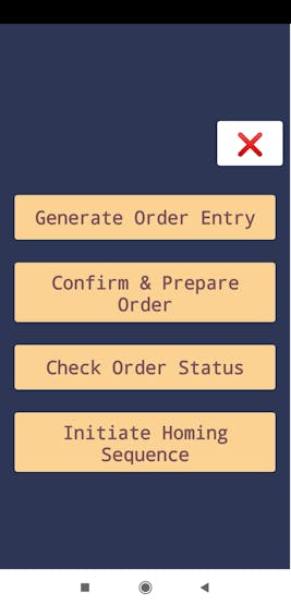
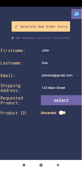
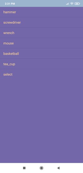
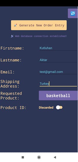
🚚📦📲 In this regard, the mobile application enables the user to select one of the available products and transfer order information to the web application.
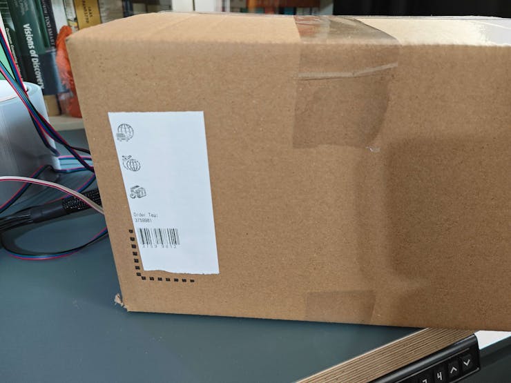
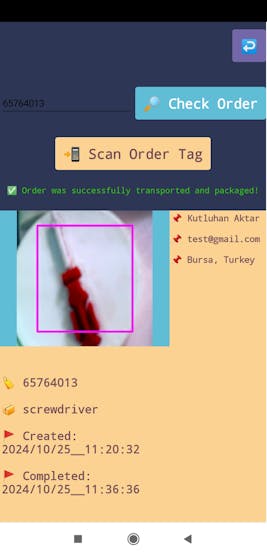
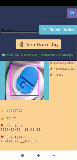
🚚📦📲 Then, the web application generates a unique order tag (barcode) number (EAN-8) and registers the received order information with the assigned order tag to the MariaDB database table hosted on Raspberry Pi 5 to generate a new shipping entry.


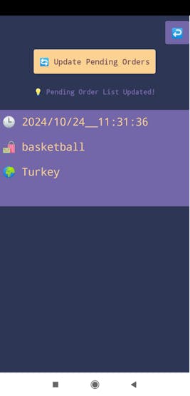
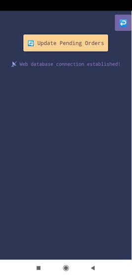
🚚📦📲 The mobile application lets the user request all pending shipping entries from the web application and review them chronologically.

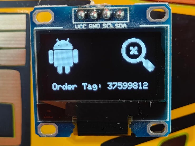
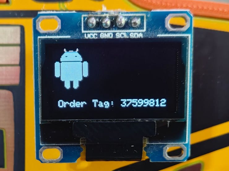
🚚📦📲 After selecting a shipping entry, the mobile application reveals its unique order tag.
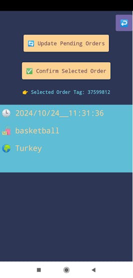
🚚📦📲 If the user activates the order confirmation process for the selected shipping record, the mobile application communicates with the web application so as to run the Edge Impulse FOMO object detection model to detect whether the sample product currently seen by the USB webcam is the ordered product of the given entry.
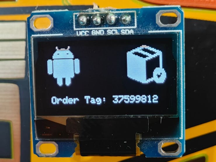
🚚📦📲 The workstation control panel notifies the user via the SSD1306 screen when the order confirmation process starts.
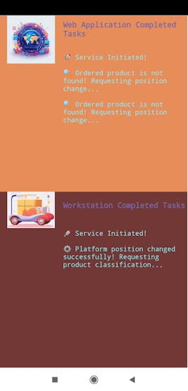
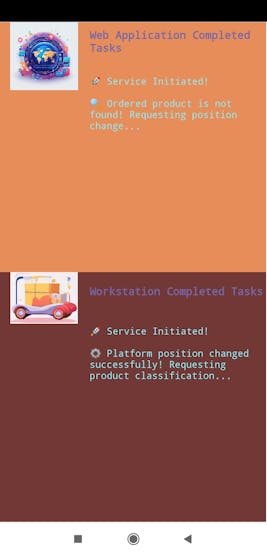
🚚📦📲 If the FOMO object detection model cannot find the ordered product, the web application dictates the mobile application to communicate with the workstation control panel so as to change the first rotating platform position to place the succeeding sample product under the USB webcam.
🚚📦📲 The workstation control panel product position change procedure:
- Swivel the first platform by 60 degrees to bring the succeeding sample product under the USB webcam.
🚚📦📲 While changing the product position, the control panel turns the RGB LED to red and notifies the user via the SSD1306 screen.
🚚📦📲 After successfully changing the product position, the mobile application dictates the web application to rerun the object detection model.

🚚📦📲 Since the mobile application exchanges data packets with the web application and the workstation control panel continuously and simultaneously as the order confirmation process continues, the mobile application informs the user of each completed task performed by the web application and the control panel via their dedicated terminals.
🚚📦📲 Until finding the requested (ordered) product successfully, the mentioned assignments continue in a loop.

🚚📦📲 When the FOMO model detects the ordered product successfully, the web application dictates the mobile application to initiate the automated product transportation process.
🚚📦📲 Then, the workstation control panel moves the ordered product from the first platform to the second platform via the transportation carrier for packaging.
🚚📦📲 While carrying the ordered product, the mobile application and the control panel inform the user of the transportation progress via the dedicated terminal and the SSD1306 screen respectively.
🚚📦📲 The workstation control panel product transportation procedure:
- Swivel the first platform by 180 degrees to prepare the requested product for transportation.
- After completion, turn the RGB LED to blue.
- Bring the transportation carrier near the first platform and adjust the carrier arm to pull the ordered product.
- Move the carrier to the road midpoint while moving (pulling) the ordered product.
- Then, rearrange the carrier position to place the ordered product towards the opposite side of the carrier.
- Adjust the carrier arm to push the ordered product.
- After completion, turn the RGB LED to yellow.
- Move the carrier to the second platform while moving (pushing) the ordered product.
- After transporting the product successfully, return the carrier to its default position.
- Finally, swivel the second platform by 180 degrees to present the retrieved product.
- After completion, turn the RGB LED to magenta.
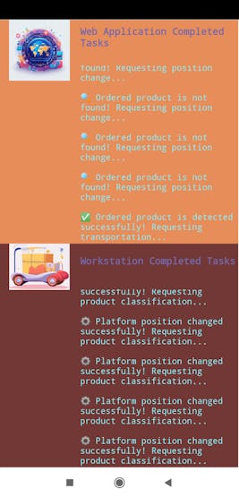
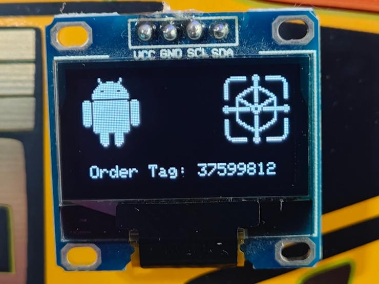
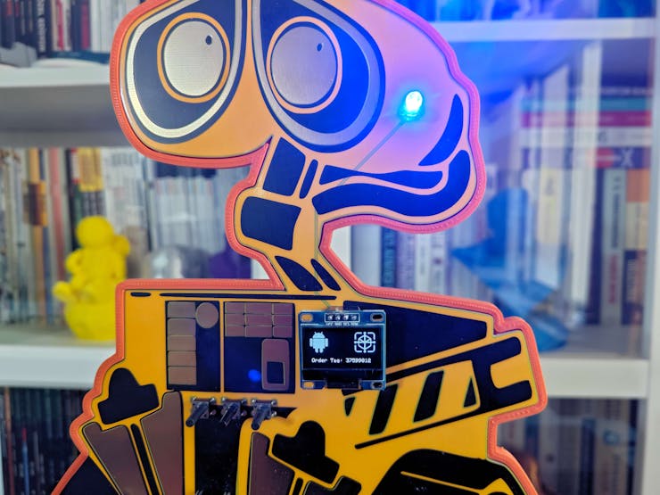
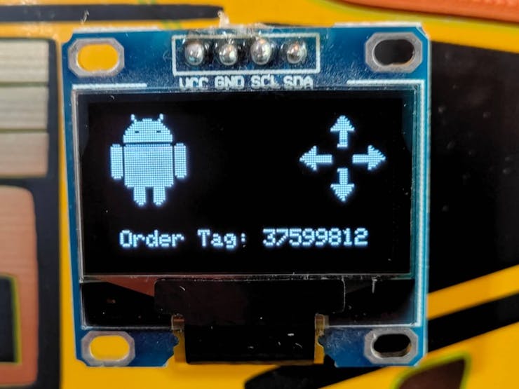
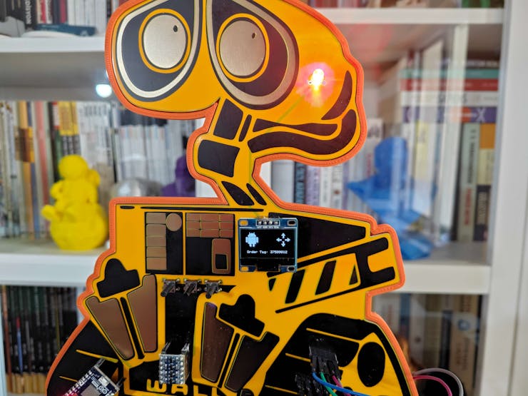
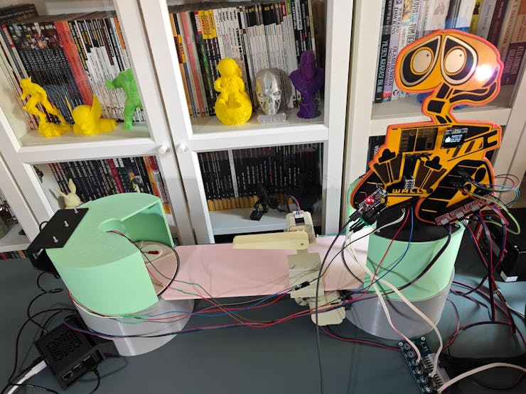
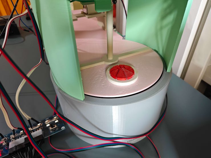
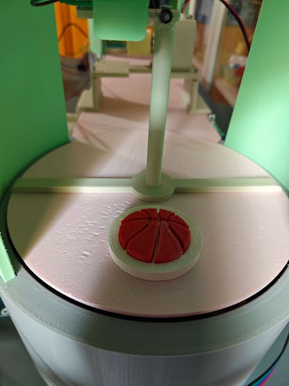
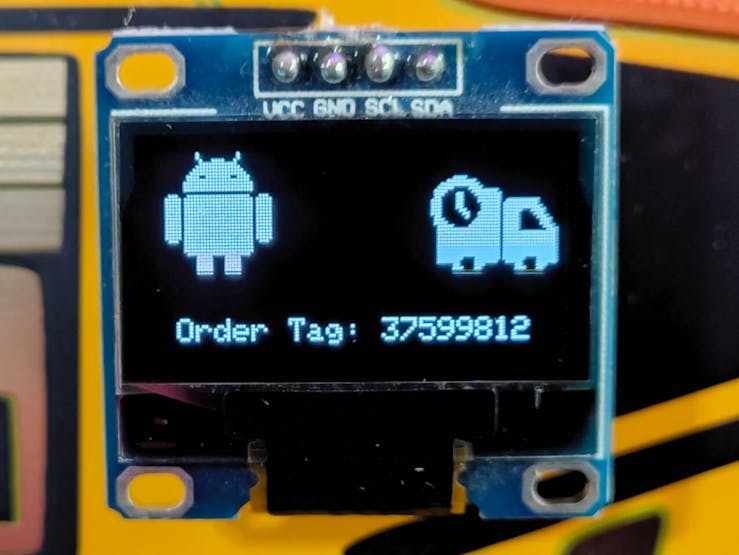
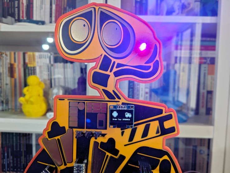
🚚📦📲 After moving the ordered product successfully, the workstation control panel prints a shipping receipt with the assigned order tag in the EAN-8 barcode format. The thermal printer utilizes a sticker paper roll to make receipts fastenable to cardboard boxes.
🚚📦📲 After printing the shipping receipt, the control panel informs the user by turning the RGB LED to green. As discussed, the mobile application also informs the user of completed tasks via the dedicated terminal.


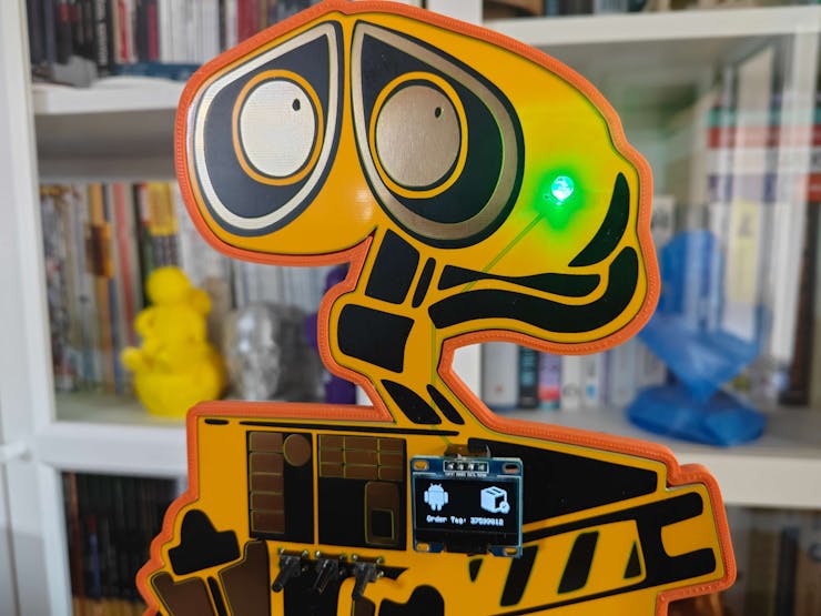
🚚📦📲 After concluding the order confirmation and product transportation processes successfully, the web application appends the completion date and the produced model resulting image path to the finalized shipping entry to remove it from the pending orders.
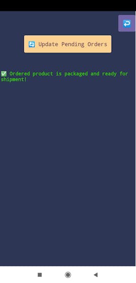
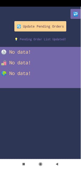
🚚📦📲 Then, the retrieved sample product becomes ready for packaging.
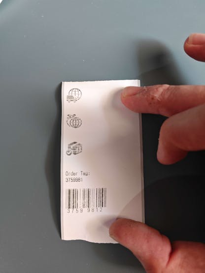
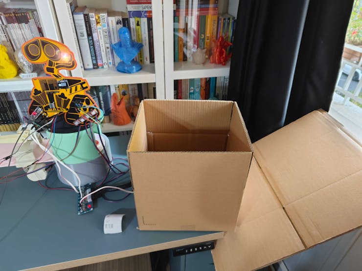
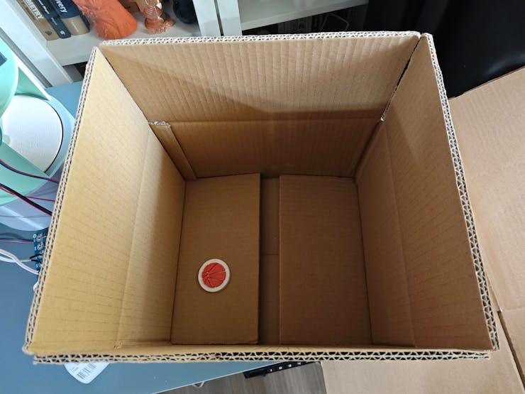
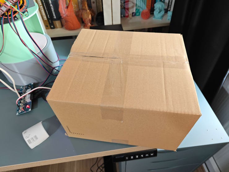
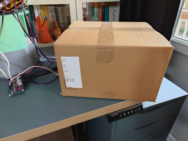

🚚📦📲 After packaging products and fastening shipping receipts to the boxes, the mobile application allows the user to scan order tags converted into the EAN-8 barcode format via the smartphone camera.
🚚📦📲 After scanning an order tag successfully, the mobile application enables the user to request detailed shipping information from the web application and review the associated model resulting image highlighting the ordered product via the modified bounding box.
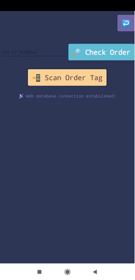
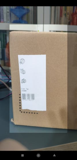

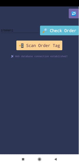
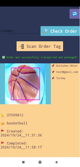

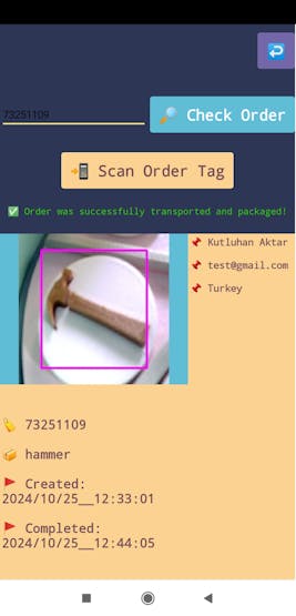
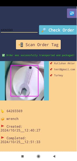

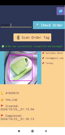
🚚📦📲 After finalizing all assignments with the workstation control panel, the mobile application lets the user terminate the established BLE connection securely via the exit (X) button on the interface.
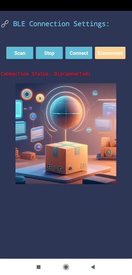

🖥️ For debugging, Nano Matter prints progression notifications on the serial monitor.
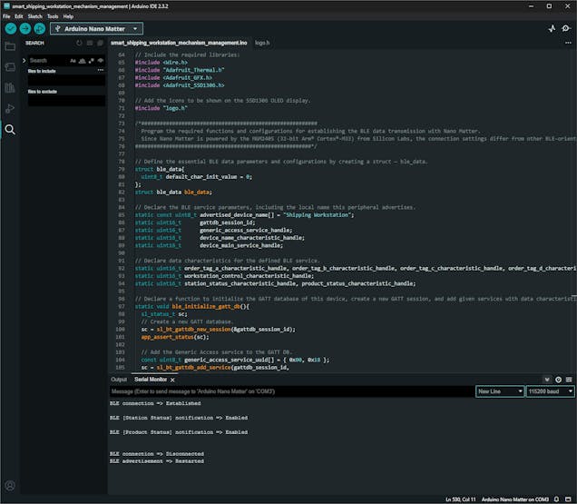
Further Discussions
By applying physically accurate digital twins to develop AI-oriented solutions for industrial-level shipping operations even before building real-world mechanisms or products, we can achieve the following:
🚚📦📲 develop adaptive product manufacturing procedures,
🚚📦📲 build secure, cost-effective, and efficient industrial facilities,
🚚📦📲 advance the precision of industrial-level shipping operations,
🚚📦📲 design safe, practical, cost-effective, and efficient real-world mechanisms,
🚚📦📲 forfend concomitant risks of assembling an industrial manufacturing system from scratch,
🚚📦📲 reduce exorbitant overhaul costs due to the lack of internal design blueprints,
🚚📦📲 review virtual components thoroughly to obtain the optimum performance from their real-world counterparts for multifaceted operations.
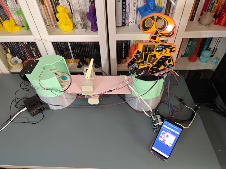
Project GitHub Repository
The project's GitHub repository provides:
- Control panel code files (Nano Matter)
- Mobile application AIA and APK files (Android)
- Web application code files (Raspberry Pi 5)
- PCB design files (Gerber)
- 3D part design files (STL and OBJ)
- Edge Impulse FOMO machine learning model (EIM)

")