Story
Project Title: Solo Design of a Custom PCB for a Multi-Mechanism Automated Sorting System
1. Project Overview:
This was a team-based mechatronics project to create an automated system for identifying, sorting, and elevating marbles. While the team collaborated on the design and construction of the three physical handling mechanisms, my primary and solo responsibility was the design, development, and integration of the entire electronic control system, culminating in a custom-designed Printed Circuit Board (PCB).
2. Key Objectives & My Role:
The team's goal was to create a functional automated sorter. My personal objectives within that were:
-
System Integration: Create a unified electronic solution to replace error-prone prototype wiring.
-
Power Management: Ensure stable and safe power delivery to all sensitive components from a single input source.
-
Component Safety: Architect the circuitry to isolate and protect components from potential damage caused by motor noise or failures.
-
Feature Implementation: Incorporate required features like wireless control and user feedback into the board design.
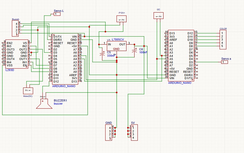
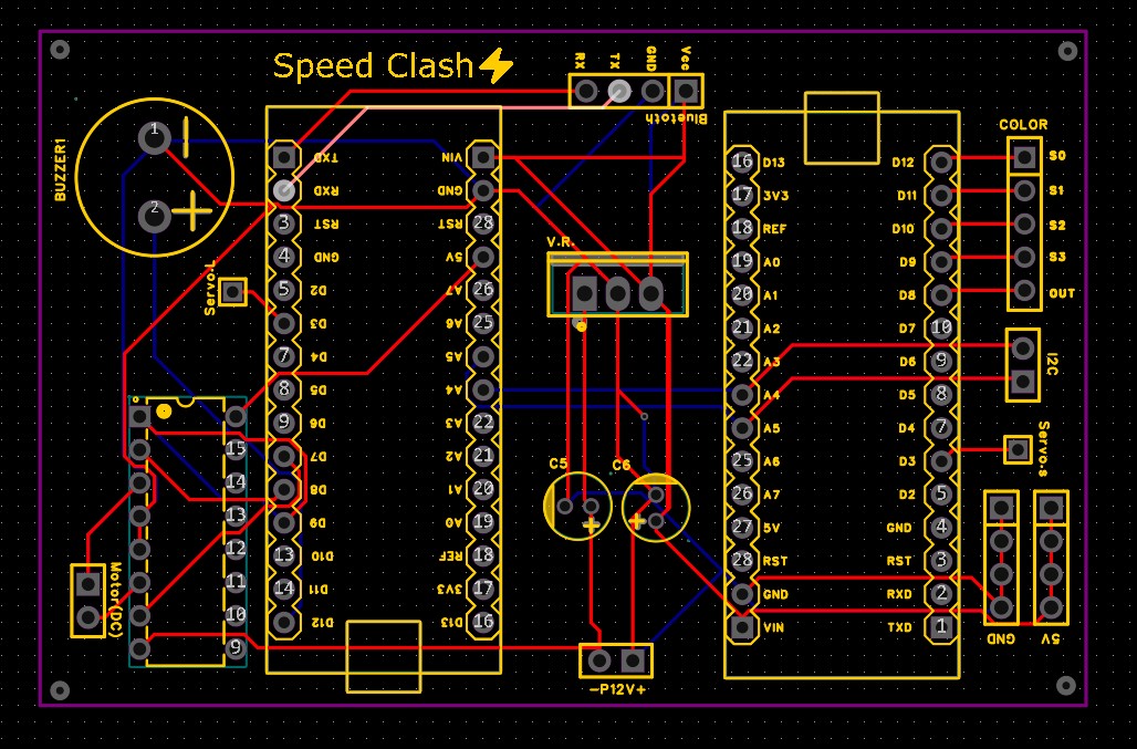
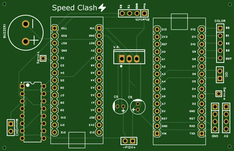
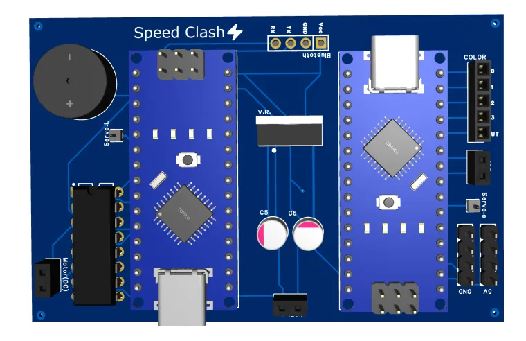
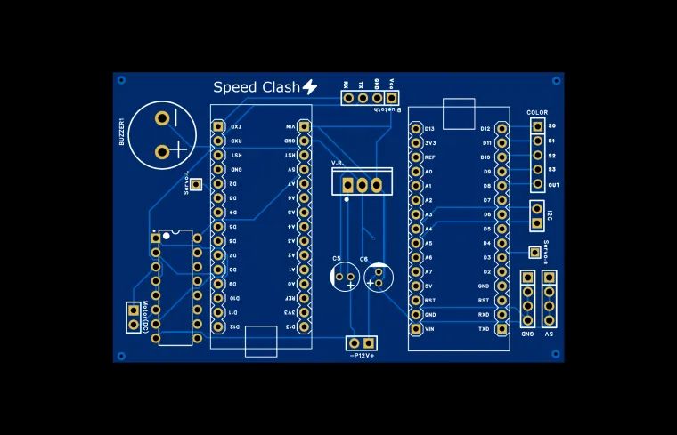
3. PCB Architecture & Design Highlights (My Solo Contribution):
I designed the following PCB to serve as the central control hub for our team's mechanisms:
-
Dual Microcontroller Configuration: I implemented two Arduino-compatible microcontrollers to efficiently handle the computational load. This architecture allowed one processor to manage sensor input and decision-making logic, while the other handled real-time motor control, ensuring smooth and responsive operation of the mechanisms built by the team.
-
Precise Motor Control: The inclusion of an H-Bridge IC was critical for interfacing the low-power microcontrollers with the high-power motors and actuators used in the mechanical designs. This allowed for precise control over direction and speed for sorting and lifting.
-
Wireless Connectivity: I integrated a Bluetooth module to provide the system with modern wireless control and data monitoring capabilities, a feature requested by the team for enhanced functionality.
-
Auditory Feedback: A buzzer was added to provide audible status updates, signaling cycle completion or errors, which was a key user-interaction requirement.
-
Robust Power Management (A Key Focus):
-
Voltage Regulator: I managed the input voltage by regulating it down to a stable 5V rail to safely power the Arduinos, Bluetooth module, and sensors.
-
Capacitors: I placed decoupling and filter capacitors strategically to smooth out voltage fluctuations and suppress electrical noise from the motors, ensuring digital logic stability.
-
-
Critical Safety Design - Parallel Circuitry: A cornerstone of my design philosophy was component isolation. I architected the board so that all critical components were in parallel, ensuring that a failure in one subsystem (e.g., a short in a motor driver) would be contained and not cascade to destroy the microcontrollers or other parts of the board. This greatly enhanced the system's overall robustness and reliability.
-
User Interface: I included an external switch header on the PCB to provide a reliable physical control point, interfacing seamlessly with the team's housing design.
4. Conclusion and Value:
This project was a successful exercise in teamwork and technical specialization. While the team delivered the mechanical solutions, I was solely responsible for the electronic architecture that brought it to life. The custom PCB I designed was more than just a convenience; it was a critical upgrade that provided professional reliability, built-in safety features, and a clean integration platform, ensuring the success of our collective project. It showcases my specific skills in PCB design, digital logic, power management, and systems-level thinking.