Currency
Toggle Nav


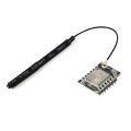
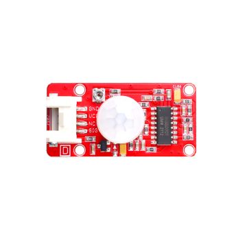
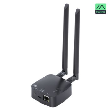
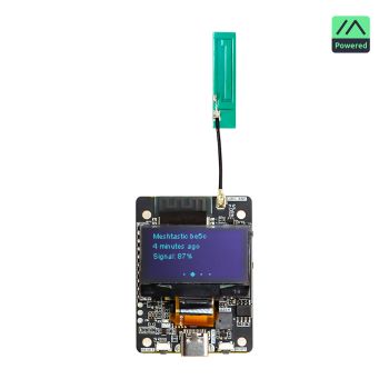
Wireless module for Crowpanel Advanced Series
As low as
$3.50
Availability:
In stock
Only %1 left
SKU
DAC0010
Brand
elecrow
Weight
20g
Related Products:


Frequently Bought Together

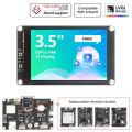
CrowPanel-ESP32 Terminal 3.5inch SPI Capacitive Touch Display with OV2640 Camera (320x480)
was
$39.90
Special Price
$35.91


Description
These modules are designed for Crowpanel Advanced series screens. With these modules, you can get extra features like WiFi 6, LoRa, etc.
Specification
- ESP32-H2 Wireless Module
|
Pin |
Pin Direction |
Note |
|
U1RXD |
Input |
Serial port 0 receiving pin |
|
U1TXD |
Output |
Serial port 0 receiving pin |
|
GPIO12 |
Input/Output |
GPIO |
|
GPIO13 |
Input/Output |
GPIO |
|
GPIO14 |
Input/Output |
GPIO |
|
3V3 |
|
Power supply |
|
GND |
|
Ground wire, connected to the power reference ground |
|
GPIO1 |
Input/Output |
GPIO |
|
GPIO0 |
Input/Output |
GPIO |
|
GPIO2 |
Input/Output |
GPIO |
|
GPIO22 |
Input/Output |
GPIO |
|
GPIO10 |
Input/Output |
GPIO |
|
GPIO11 |
Input/Output |
GPIO |
|
BOOT |
Press and then tap the RST key to enter the burning mode |
|
|
RST |
Press it to re-run the program and also to burn the program. |
|
Chip performance
|
Chip Model |
ESP32-H2FH4 |
|
|
FLASH |
4MB Quad SPI |
|
|
SRAM |
320KB |
|
|
ROM |
128KB |
|
|
LP memory |
4KB |
|
|
Ambient temperature |
-40℃~105℃ |
|
|
Voltage |
3.3V |
|
|
Bluetooth Low Energy Radio Specifications |
||
|
Working channel center frequency range |
2402~2480MHz |
|
|
RF transmission power range |
-24.0~20.0dBm |
|
Patch Antenna Performance
|
Gain and efficiency |
Bandwidth 2.4G~2.5GHz |
|
Peak Gain |
4.33dBi |
|
Average Gain across the band |
4.0dBi |
|
Gain Range across the band |
3.59dBi~4.33dBi |
|
Peak Efficiency |
62.5% |
|
Average Efficiency across the band |
57.5% |
|
Efficiency Range across the band |
51.3%~62.5% |
- ESP32-C6 Wireless Module
|
Pin |
Pin Direction |
Note |
|
U1RXD |
Input |
Serial port 0 receiving pin |
|
U1TXD |
Output |
Serial port 0 receiving pin |
|
GPIO0 |
Input/Output |
GPIO |
|
GPIO1 |
Input/Output |
GPIO |
|
GPIO2 |
Input/Output |
GPIO |
|
3V3 |
|
Power supply |
|
GND |
|
Ground wire, connected to the power reference ground |
|
GPIO23 |
Input/Output |
GPIO |
|
GPIO22 |
Input/Output |
GPIO |
|
GPIO21 |
Input/Output |
GPIO |
|
GPIO20 |
Input/Output |
GPIO |
|
GPIO19 |
Input/Output |
GPIO |
|
GPIO18 |
Input/Output |
GPIO |
|
BOOT |
Press and then tap the RST key to enter the burning mode |
|
|
RST |
Press it to re-run the program and also to burn the program. |
|
Chip performance
|
Chip Model |
ESP32-C6FH4 |
|
|
L1 cache |
32KB |
|
|
ROM |
320KB |
|
|
HP SRAM |
512KB |
|
|
LP SRAM |
16KB |
|
|
FLASH |
4MB Quad SPI |
|
|
Ambient temperature |
-40℃~105℃ |
|
|
Voltage |
3.3V |
|
|
Bluetooth Low Energy Radio Specifications |
||
|
Working channel center frequency range |
2402~2480MHz |
|
|
RF transmission power range |
-15.0~20.0dBm |
|
|
WIFI RF Specifications |
||
|
Working channel center frequency range |
2412~2484MHz |
|
|
Wireless Standards |
IEEE 802.11b/g/n/ax |
|
- Patch Antenna Performance
|
Gain and efficiency |
Bandwidth 2.4G~2.5GHz |
|
Peak Gain |
3.74dBi |
|
Average Gain across the band |
3.66dBi |
|
Gain Range across the band |
3.45dBi~3.74dBi |
|
Peak Efficiency |
58.9% |
|
Average Efficiency across the band |
55.9% |
|
Efficiency Range across the band |
53.0%~58.9% |
- nRF2401 Wireless Module
|
Pin |
Pin Direction |
Note |
|
CE |
Input |
Module control pin |
|
SCK |
Output |
SPI Data Pin |
|
MISO |
Input |
SPI Data Pin |
|
MOSI |
Output |
SPI Data Pin |
|
3V3 |
|
Power Supply |
|
GND |
|
Ground wire, connected to the power reference ground |
|
CSN |
Input |
Module chip select pin, used to start an SPI communication |
|
IRQ |
Input |
Module interrupt signal output, low level is effective |
Chip performance
- Chip Model:nRF24L01+
- Worldwide 2.4GHz ISM band operation
- 250kbps, 1Mbps and 2Mbps on air data rates
- Ultra low power operation
- 11.3mA TX at 0dBm output power
- 13.5mA RX at 2Mbps air data rate
- 900nA in power down
- On chip voltage regulator
- 1.9 to 3.6V supply range
Patch Antenna Performance
|
Gain and efficiency |
Bandwidth 2.4G~2.5GHz |
|
Peak Gain |
3.74dBi |
|
Average Gain across the band |
3.66dBi |
|
Gain Range across the band |
3.45dBi~3.74dBi |
|
Peak Efficiency |
58.9% |
|
Average Efficiency across the band |
55.9% |
|
Efficiency Range across the band |
53.0%~58.9% |
- SX1262 Wireless Module
|
Pin |
Pin Direction |
Note |
|
DIO1 |
Input/Output |
Configurable general purpose IO ports |
|
SCK |
Input |
SPI Data Pin |
|
MISO |
Input |
SPI Data Pin |
|
MOSI |
Output |
SPI Data Pin |
|
3V3 |
|
Power supply |
|
GND |
|
Ground wire, connected to the power reference ground |
|
NRESET |
Output |
Chip reset trigger input pin, low level is effective |
|
DIO2 |
Input |
RF switch send/receive control pin, low level is receiving, high level is sending |
|
BUSY |
Output |
Used for status indication |
|
NSS |
Input |
Module chip select pin, used for SPI communication |
|
DIO3 |
Input/Output |
Configurable general purpose IO ports |
Antenna Performance
|
Gain(dBi) |
3.5dBi |
|
VSWR |
<=1.9 |
|
Input impedance(Ω) |
50 |
|
Polarization |
Vertical |
|
Lightning Protection |
DC Ground |
|
Mechanical Specification |
|
|
Wire Spec |
RF1.13 |
|
Wire length(cm) |
10cm |
|
Input connector type |
IPEX-1 |
|
Antenna weight(kg) |
0.01 |
|
Operating temperature |
-40℃~85℃ |
Package List
- 1x Wireless Module
Wiki & External links
Write Your Own Review
-
 A reusable template for makers: touch UI, instant reaction, and MCU-based neural speech. CrowPanel UI + TinyTTS voice: instant offline speech on the MCU, ready to extend and remake.
Build a Talking Quiz About Animals
14777180 -
 A weather station that talks, powered by real on-device neural speech. Build it once — then make anything you want speak.
Hear Your Weather — Build a Talking Weather Station
1319181 -
 Beyond Beeps and MP3 Clips: Real Voice on MCUs.
The First Neural Speech Module for Makers: tinyTTS kit
175710310 -
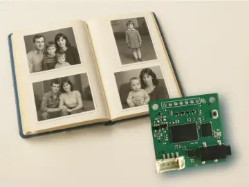 Your pictures don’t just sit there anymore — they speak. Add short captions to your family album, and turn them into natural voice
TinyTTS — The Neural Module That Makes Photos Talk
1272180 -
 Connect your device via USB, launch the app, paste Wi-Fi and keys, click "Send" — done in 10 seconds.
Send Wifi, Keys & Initial Data over USB from PC to CrowPanel
11475200 -
 An interactive English learning game enhanced with CrowPanel, adding voice recognition, scoring, and real-time visual feedback for kids.
CrowPanel Game Interface for AI Learning
1479180 -
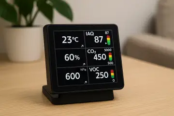
 Displays real-time indoor data (temperature, humidity, pressure, IAQ, CO₂, VOC) and live weather forecasts. Easy setup with prebuilt firmware. Fully open-source and customizable.
Weather & Air Quality Station (EnSens Add-on & CrowPanel)
14907191 -
 Turn your CrowPanel Advance into a smart indoor air monitor with the EnSens Add-on. Get real-time data on temperature, humidity, pressure, IAQ, CO₂, and VOCs—visualized with trend arrows and color alerts. Easy plug-in setup, open-source firmware, and instant installation.
MiniMeteo: Compact Indoor Air Quality Station for CrowPanel
9273170 -
 Voice-controlled robot interface using CrowPanel Advance and OpenAI. Spoken commands are interpreted via API and sent over Bluetooth to a robot. Works with CrowBot and can be adapted for other devices.
Natural Language Robot Control via CrowPanel + OpenAI
3635407 -
 A ready-to-use weather station. Quick setup: flash the prebuilt firmware and start testing in under a minute, no coding required. Open-source and customizable for your own weather-based projects. Firmware and source code available on GitHub.
Simple Weather Station on CrowPanel Advance
5116342 -
 OpenAI Terminal is an AI-powered voice assistant designed for the Elecrow CrowPanel Advance. It enables real-time communication with OpenAI models via WebRTC, providing hands-free interactions. Users connect via Wi-Fi, authenticate with an OpenAI API key, and access features like live transcriptions and model responses.
Open AI Terminal
4546335 -
 Turn the Elecrow CrowPanel on ESP32-P4 into an interactive AI storybook with animated scenes, local voice playback, and touch interaction
Magic Talking Storybook on ESP32-P4
6929160

Bestselling Products You May Like


New Products You May Want


Warranty
Service
VIP Distributor
Discount
Professional
Tech Support
Fast
Delivery
×
 Add to cart successfully!


Customers Who View This Item Also Bought