Story
Testing operational amplifiers (Op-Amps) efficiently is a crucial step in the prototyping and repair processes of electronic circuits. To simplify this task, we’ve designed a dedicated Op-Amp IC Tester PCBA that allows users to quickly verify the functionality of common Op-Amps such as UA741, LM358, LM833, and LM324—and potentially other similar Op-Amps with matching input/output specifications.
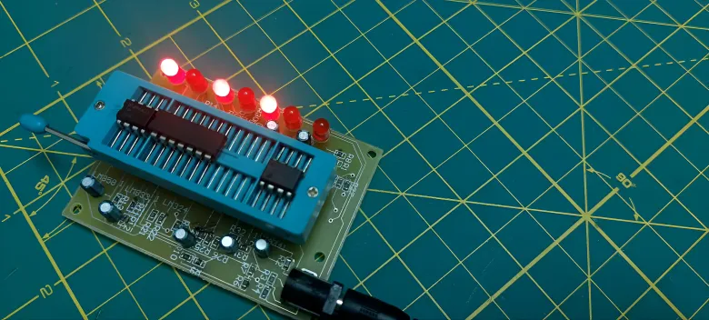
The design of the PCBA (Printed Circuit Board Assembly) includes SMD resistors, standard capacitors, a 40-pin ZIF (Zero Insertion Force) socket, a DC power jack, and seven indicator LEDs. The core concept behind the tester is simple: insert the Op-Amp into the correct position in the ZIF socket based on its datasheet pin configuration, lock the socket, and supply 12V DC power. If the connected LED blinks, it indicates that the Op-Amp under test is working properly.
Correct orientation and positioning in the ZIF socket is critical for accurate testing. The layout is designed to be user-friendly, with clear markings to assist in Op-Amp placement. The tester supports multiple IC types, and while it is optimized for four widely used models, it can also test other Op-Amps with similar internal architecture and pin compatibility.
This Op-Amp tester is ideal for electronics hobbyists, repair technicians, and educators who frequently work with analog circuits. Its compact design and ease of use make it a practical tool for any electronics lab or DIY workspace.
By offering fast, visual feedback through LED indicators and eliminating the need for complex testing equipment, this tester improves efficiency and reduces guesswork in Op-Amp evaluation.