
Story
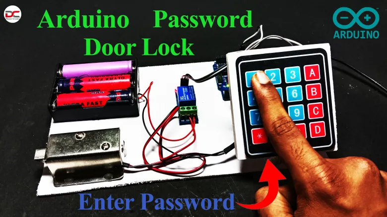
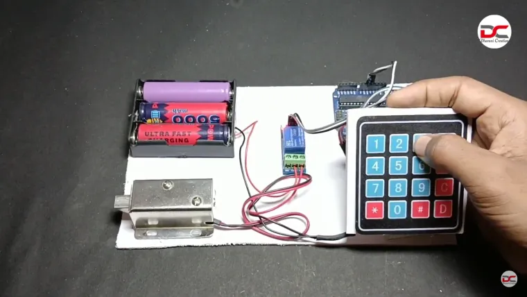
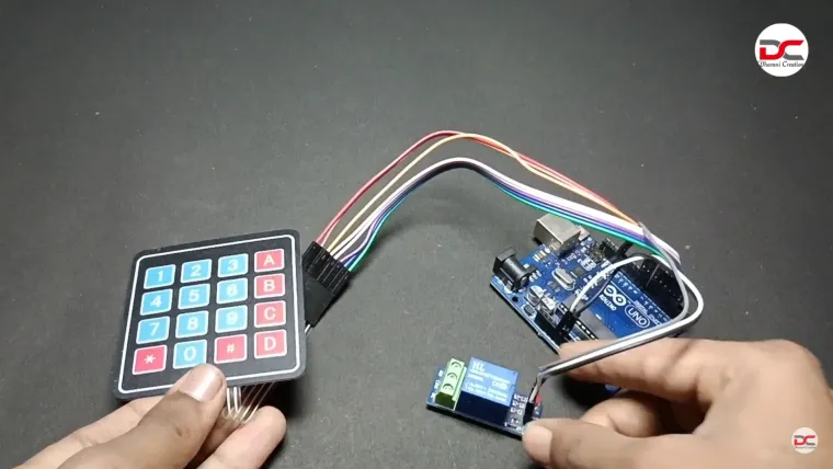
Project Title: Arduino-Based Keypad Door Lock System
Overview:
This project demonstrates a basic electronic security system using an Arduino Uno, a 4x4 keypad, and a relay-controlled electric lock. When a predefined PIN code is entered correctly on the keypad, the Arduino activates a relay that unlocks the door for a short duration, then automatically locks it again. If an incorrect code is entered, access is denied. This system can be expanded with features like an LCD display, buzzer alerts, multiple user PINs, and tamper detection.
Key Project Components & Functionality
| Component | Purpose |
|---|---|
| Keypad | Captures user input of numeric code |
| Arduino Uno | Processes input, compares against stored PIN, and activates relay |
| Relay Module | Safely switches high-current for electric lock |
| Electric Lock | Locks/unlocks door via electric signal powered through relay |
| LCD & Buzzer | (Optional) Displays prompts, confirms or denies access via sound and visual feedback |
| Power Supply | Typically 5 V for Arduino; 12 V for many electric locks |
Workflow:
-
Arduino reads each keypress from the keypad.
-
Entered code is stored in memory.
-
Once confirmed (e.g. by pressing ‘#’ key), Arduino verifies the PIN.
-
If correct: activate relay to unlock for ~X seconds (configurable).
-
If incorrect: deny access, optionally trigger buzzer.
Implementation Steps (as shown in the video)
-
Wiring setup
-
Connect keypad rows/columns to Arduino digital pins.
-
Hook relay IN pin to Arduino output, relay’s NO/NC lines to lock supply.
-
(Optional) Attach LCD and buzzer for user interface.
-
-
Arduino Code Structure
-
Libraries:
<Keypad.h>, optionally<LiquidCrystal.h> -
Define keypad layout, PIN code, and timing for unlock.
-
Loop logic:
-
Scan keypad input
-
Build code string
-
Upon entry complete, perform PIN check
-
Trigger relay if correct, else deny
-
-
-
Testing & Adjustment
-
Power supply management: ensure lock and Arduino have correct voltage levels.
-
Test with correct and incorrect codes.
-
Fine‑tune unlock duration and error handling.
-
-
Safety Enhancements (optional)
-
Add a mechanical override or backup power.
-
Store PIN securely; avoid hardcoding in plaintext.
-
Add tamper or failed‑attempt alert.
-
Optional Enhancements & Ideas
-
Multiple user PINs with different access levels
-
Tamper lockout after multiple wrong attempts
-
Wireless control via Bluetooth/Wi‑Fi (e.g. ESP8266 module)
-
Logging events to SD card or server for audit trail
-
App-based control, using mobile interface or RFID/NFC integration
What You’ll Learn
-
Interfacing numeric keypad with Arduino
-
Interfacing relay module to control high‑power devices
-
Basic code structure for PIN authentication
-
Relay timing and safety considerations
-
Optional feedback with LCD and buzzer
Working Principle:
-
User inputs a numeric password via the keypad.
-
Arduino compares it with a predefined PIN.
-
If correct → relay is triggered → door unlocks.
-
If incorrect → system denies access.
-
After a set time, the system re-locks the door.
Applications:
-
Home or office door automation
-
Basic IoT security projects
-
School/college mini-projects
Skills Demonstrated:
-
Embedded programming (Arduino)
-
Use of digital I/O, keypad matrix scanning
-
Relay and electric lock control
-
Basic security logic design