Story
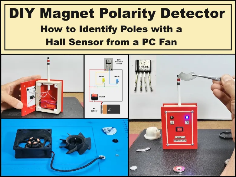
Recently, while working on a project, I needed to determine the polarity of several permanent magnets of different shapes. At first glance, it seemed simple, bringing the magnets closer together to see if they attract or repel, but I still couldn't determine it precisely this way. So I came up with the idea of making a very simple electronic device that would display the poles of the magnets in a very elegant way with two LEDs with different colors for each pole.
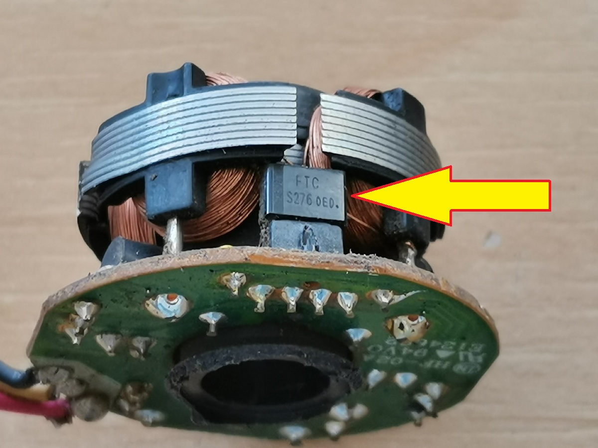
It can immediately be assumed that for this purpose we need a Hall effect sensor with appropriate properties, which is not a standard component that would be available even in a well-stocked electronics store. There is no DIYer who will not find at least one brushless PC cooler fan in their lab, functional or non-functional. In almost more than 90 percent of these fans you will find one of the two most commonly used Hall effect sensors, which are the FS276 or FS277.
First I will explain the way to remove the sensor, which is basically the same for all types of brushless PC fans. In fact, I am specifically using a fan from an old UPS unit. First we need to remove the sticker with informations on the back, and then under it there is a rubber cover that covers the axis of the rotor.
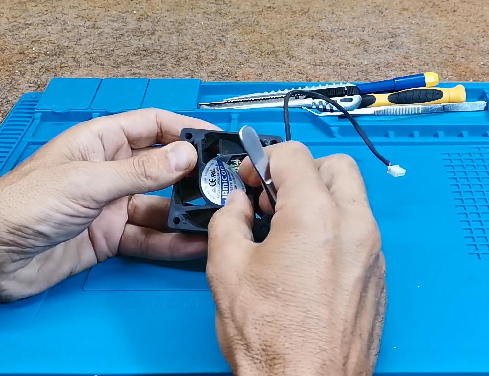
Otherwise, by default, this hole is used for lubrication if the fan is stuck, and we want to fix it. Next, we need to use a small screwdriver or tweezers to remove the plastic fuse, after which the rotor easily comes out of the bearing.
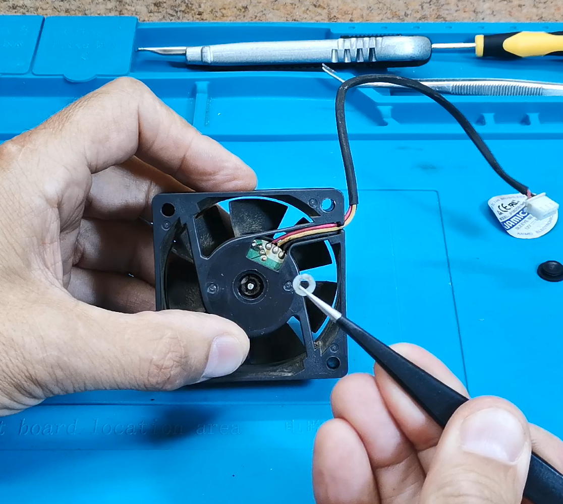
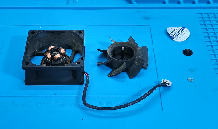
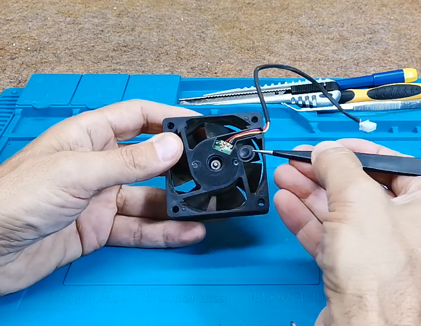
Now we need to remove the stator, under which we can see a round PCB on which the Hall sensor is soldered.
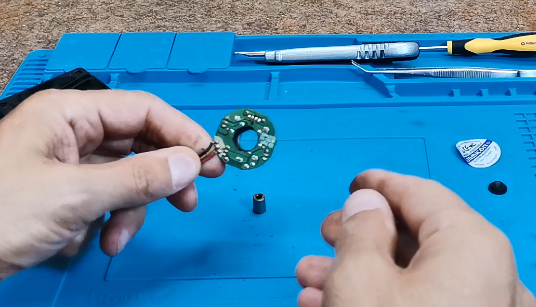
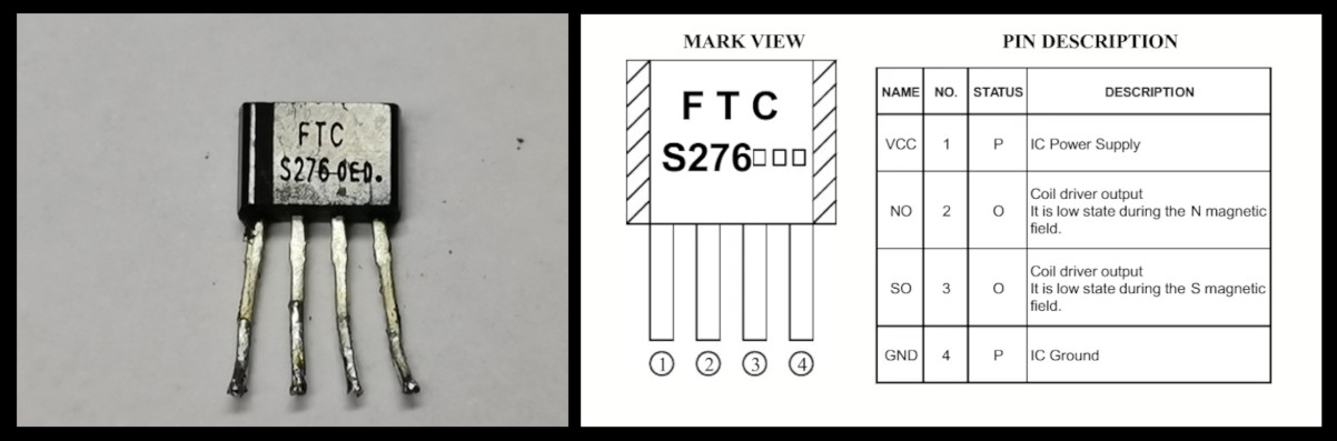
This circular PCB contains the sensor we need for this project. It looks like a small transistor but has 4 pins. Then we will simply unsolder the sensor and use it to make our device.
As I mentioned earlier, the device is extremely simple and consists of only a few components:
- FC276 Hall Effect Sensor
- 2 Leds with different colors
- Resistor 1kohm
- Ad 9V Battery with switch
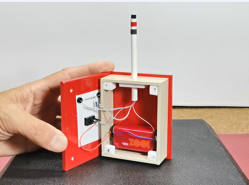
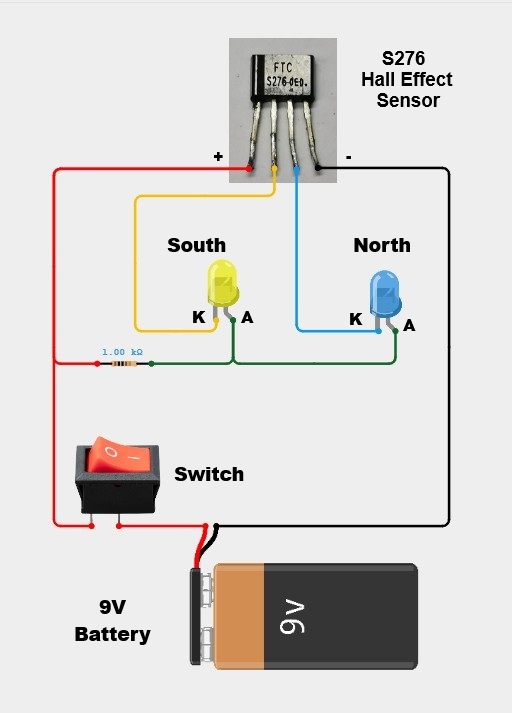
As you can see, this extremely simple device does not require a PCB, but the elements are directly interconnected according to the given Schematic.
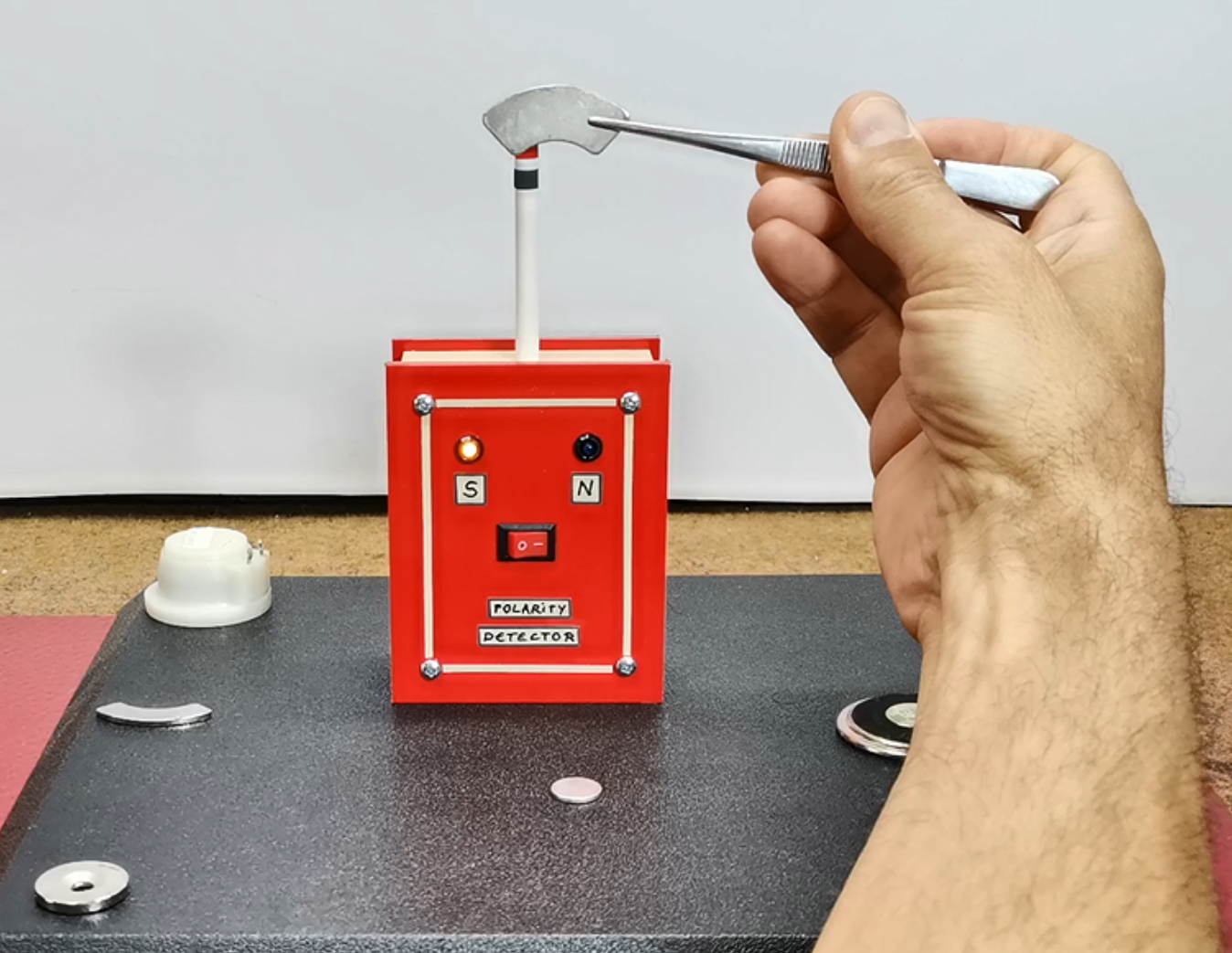
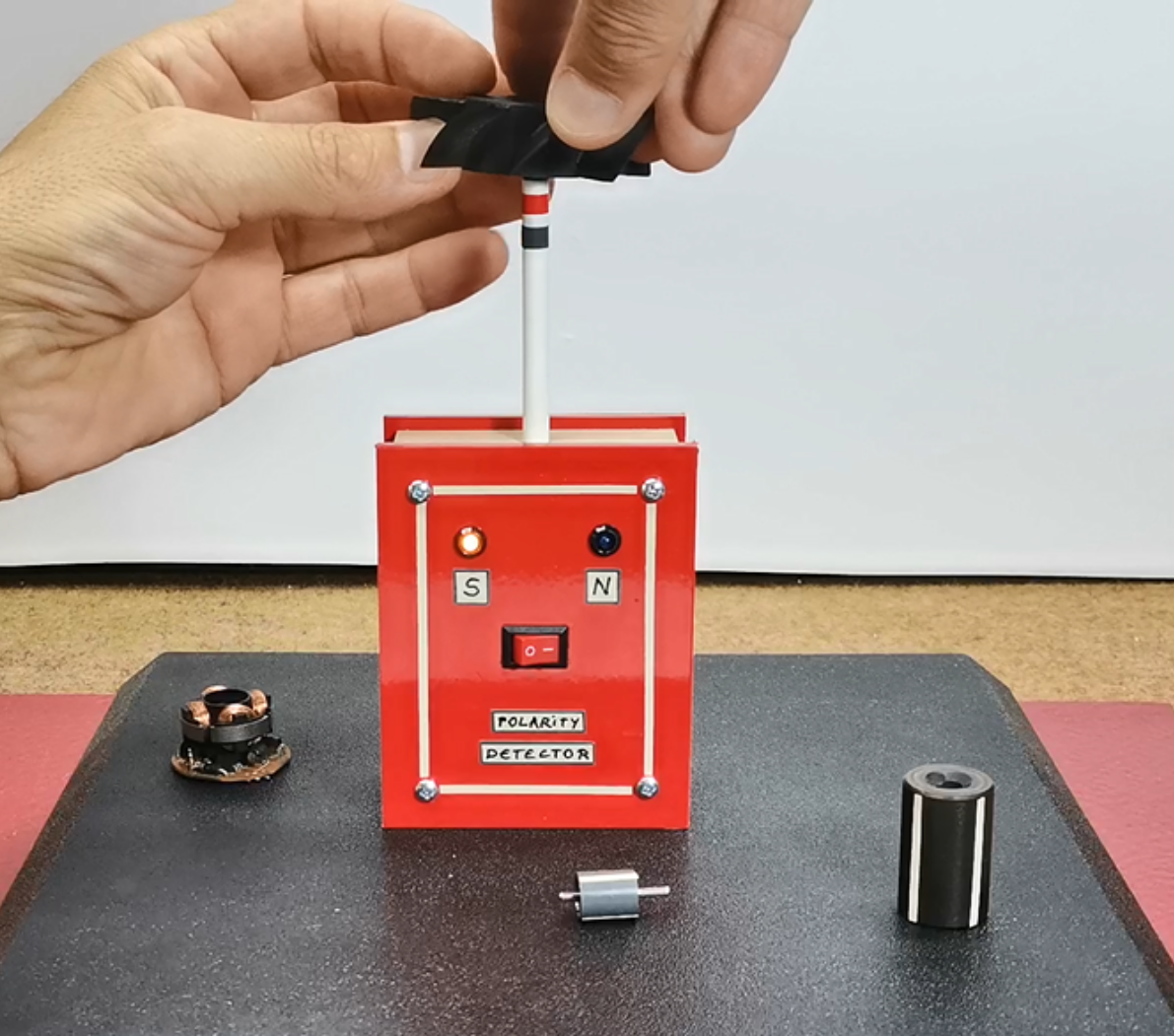
Now let's see how the device works in real conditions. Immediately after switching on, the blue (North) LED lights up, which actually represents only a sign that the device is turned on and the detector will start functioning the moment we bring the magnet closer to the sensor. I could have easily solved this, relatively speaking, initial drawback with an Arduino microcontroller and simple code, and even added some additional options, but the basic requirement when making the device was that it be as simple, and easy to make as possible.
In the following, I will demonstrate how you can easily determine the poles of magnets with different shapes.
Next I will present you few special cases where we can detect the arrangement of the poles of the magnet only with such an instrument and no other way.
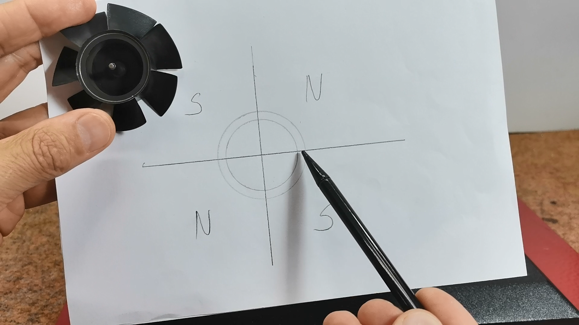
Torus-shaped magnet is used in brushless motors, specifically in this case for a fan. If we pass the sensor along the entire shape of the magnet, we will notice that the polarity changes every 90 degrees. Here's what the pole arrangement looks like for this type of magnet:
If we now look at the stator of this motor, we will see that there are 4 coils on it, also arranged at an angle of 90 degrees. So the motor works in such a way that these coils are activated one by one and create a rotating magnetic field that moves the rotor.
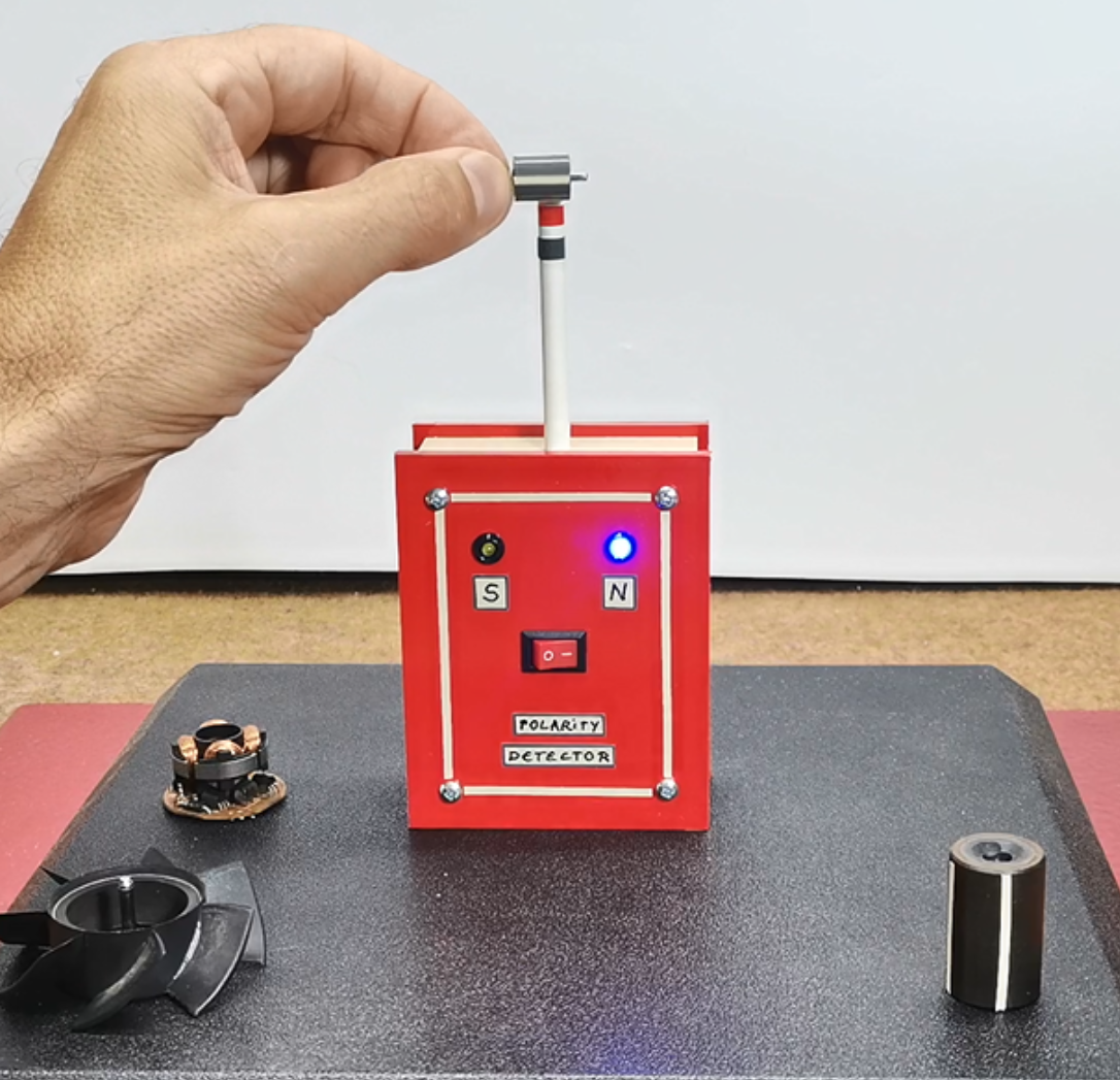
I have also a cylindrical magnet taken from a small brushless motor, and if we rotate it horizontally past the sensor, we will see that the poles alternate. And Another bigger cylindrical magnet rotor
And finally a short conclusion. This simple, self-made device effectively identifies magnet polarities, even for complex shapes, proving that sometimes the best tools are the ones you build yourself from readily available parts.