


Story
Hi makers!
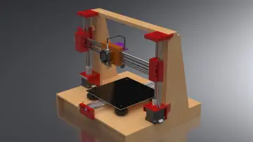
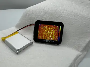
I'm entering this competition with a small project that I've wanted to make for some time, it's a turntable made of cardboard and with plenty of components recovered from electronics boards.
One of the most fundamental problems in robotics is controlling the speed of a DC motor. The most common method of speed control is PWM or Pulse Width Modulation which is is the process of changing the power to a device by switching it on and off at a given frequency. These switchings on and off are referred to as “Duty Cycle”. So, "Duty Cycle" describes the width of a pulse in percentage. A Duty Cycle of 10% means that 10% of the time our load is receiving current compared to 90% of the time it is not.
A Duty Cycle of 100% means that our load is receiving current all the time and we would not need a PWM. These signals are sent to the motor at a high enough frequency that the pulsing has no effect on the motor. The end result of the PWM process is that the total power sent to the motor can be adjusted from (0% Duty Cycle) to (100% Duty Cycle), with good efficiency and stable control.
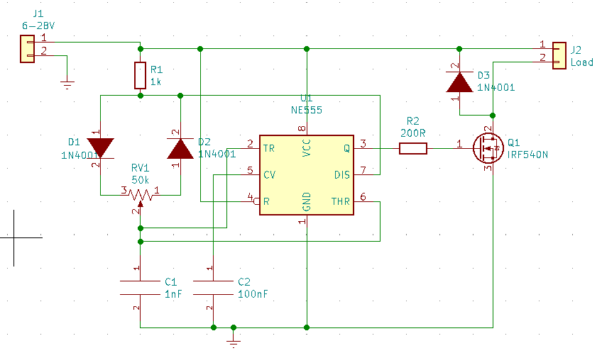
The 555 timer in the PWM circuit is configured as an astable oscillator. This means that once power is applied, the 555 will oscillate, without any external trigger. With this type of circuit, you can control the speed of a motor from 0% to 100%, keeping the torque constant. In principle, the NE555 circuit generates a signal of a certain frequency that is applied to a monostable whose period is determined by the value of a resistor. Both N-channel transistors can be used, but there are also circuit variants with P-channel transistors, with the difference that in this case the load is between the source and the force ground and the drain to the power where the plus voltage is connected.
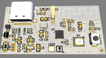
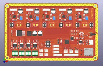
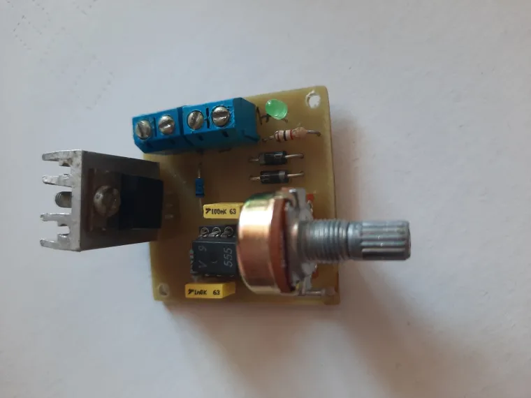
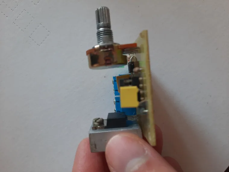
As for the circuit, it is a very well-known one and the PCB is made by me at home (through processes well-known to others, using an iron and its heat), although I made some mistakes in the end the circuit is functional. Most of the components are recovered from other electronic boards (good thing they don't have expiration dates 😁).
Circuit
The rest is manual work, I used cardboard because it is easier to process but at the same time I didn't get the desired result and I have to find another idea for making it. 😅
Bill of materials
| Ref | Value | Source |
| C1 | 1nF | New |
| C2 | 100nF | Salvaged |
| D1 | 1N4001 | Salvaged |
| D2 | 1N4001 | Salvaged |
| D3 | 1N4001 | Salvaged |
| J1 | Terminal block | Salvaged |
| J2 | Terminal block | Salvaged |
| Q1 | IRF740 | Salvaged |
| R1 | 1kΩ | Salvaged |
| R2 | 200Ω | New |
| RV1 | 50kΩ | New |
| U1 | NE555 | Salvaged |
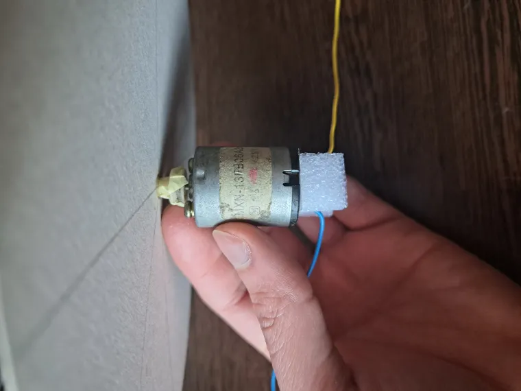
| DC Motor | Salvaged | |
| Switch+DC jack | New | |
| 9V supply | Salvaged |
And a short video: https://drive.google.com/file/d/1ReyVJXjNRaQkBfCfophqL5W9pQO_6rdI/view?usp=sharing
Thanks and have a great day!