


Story
Project goal
The goal of this project is to improve the linearity of an R-2R DAC based on the PCM58 chip. If you are an audiophile and you own a DAC or a CD player using this chip, this project is for you.
The PCM58 is an 18-bit DAC manufactured by Burr-Brown. It is known for a very pleasant, warm, and detailed sound that is often hard to achieve with modern delta-sigma converters. Unfortunately, it also has drawbacks. One of them is a large production spread (unit-to-unit variation) and a wide spread of nonlinearity between individual chips. This was a real issue for manufacturing in the 1990s.
To address this, Burr-Brown allowed external trimming of the chip to improve conversion linearity. However, the trimming procedure described in the PCM58 datasheet is inconvenient and not well suited to industrial production. As a result, in many CD players and DACs that used the PCM58, there is no external tuning circuit.
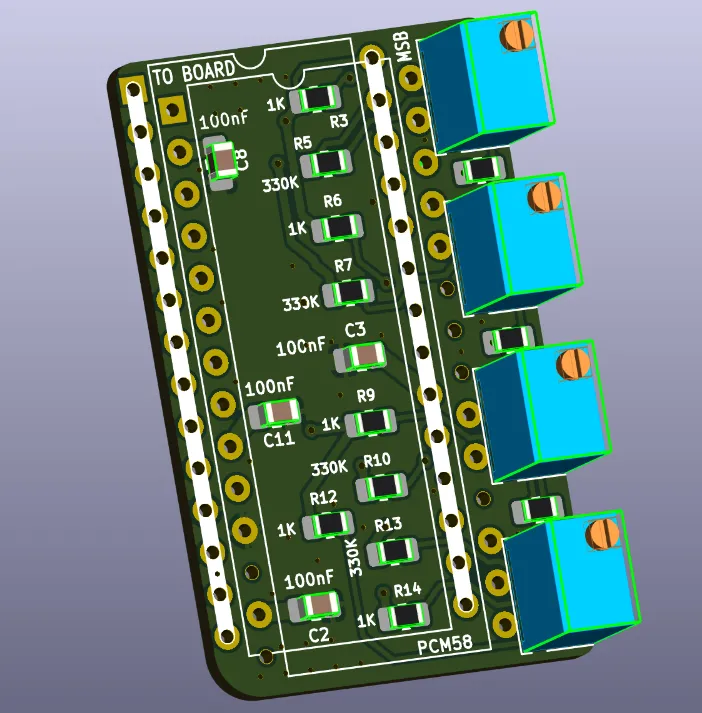
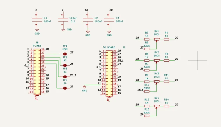
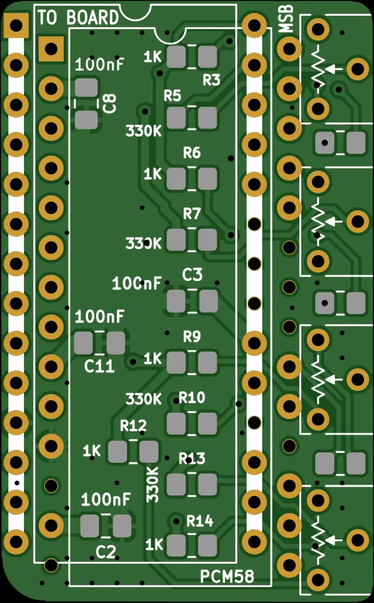
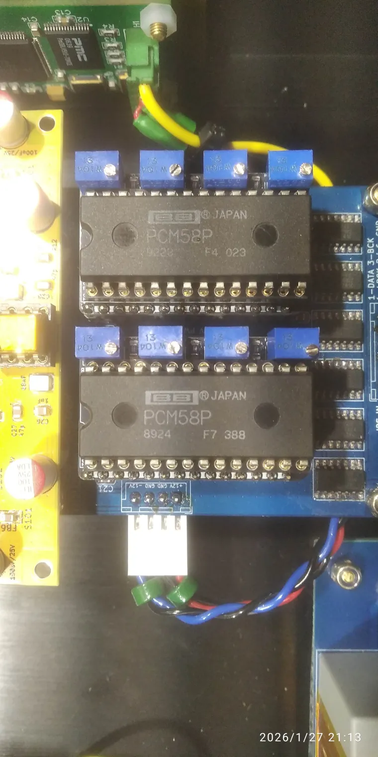
This adapter restores that functionality and adds an external network of resistors and trimmer potentiometers that allow you to tune the 4 most significant bits (MSB) of the converter.
Installation
To install the adapter, you must desolder the PCM58 and install a wide DIL28 socket in its place, preferably a round-pin type. Then insert the adapter into the socket on the PCB, and insert the PCM58 into the adapter.
Tuning procedure
For each step, you should power the DAC off and on and let it warm up for a short time.
-
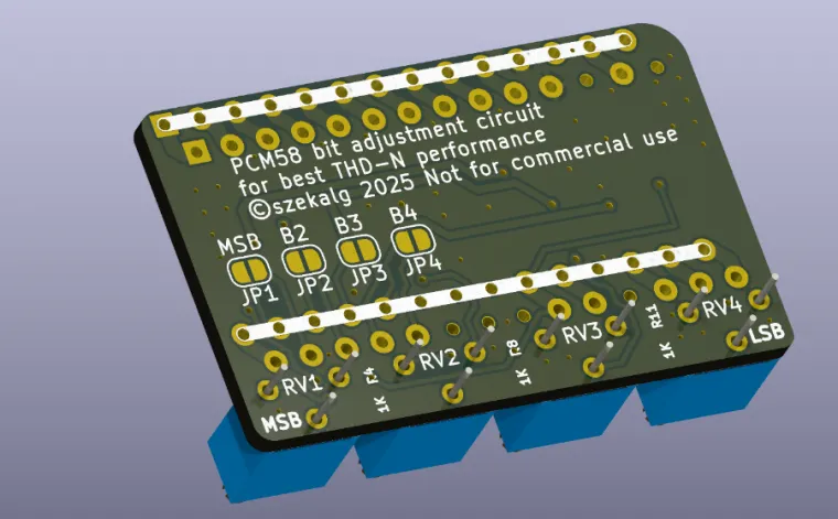
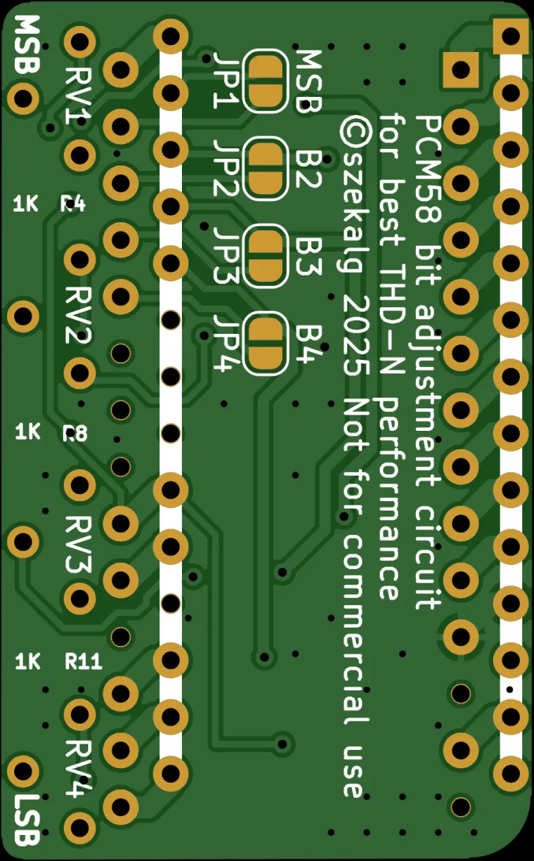
Short solder jumper J1 on the bottom side of the adapter for the MSB bit (marked “MSB”). Play a file with a 1 kHz sine wave at -60 dB through the DAC (almost silence). Then turn trimmer RV1 until the output spectrum shows the lowest possible THD.
-
Next, short jumper J2 on the bottom side of the adapter. This time you will tune MSB-1. Play a 1 kHz sine wave at 0 dB. Then adjust trimmer RV2 until the output spectrum shows the lowest possible THD.
-
Repeat step 2 for jumpers J3 and J4, respectively for bits MSB-2 and MSB-3.
Measurement without an oscilloscope
If you do not have an oscilloscope to monitor harmonic content in the output signal, a very good solution is a high-quality external sound card. Connect the DAC output to the sound card’s line input. Typical output level from a DAC or CD player is about 2 Vrms, which fits within the line input range.
Make sure the sound card is good quality and has low distortion on the line input, so it does not significantly affect the measurement. An older Sound Blaster HD class card can work well. As measurement software you can use the free program Visual Analyser (a software oscilloscope).
Generating test signals
Some streamer software (for example PiCorePlayer) includes plugins for a digital signal generator and can be used to generate a sine wave. If you want to use the module inside an older CD player with PCM58, it becomes a bit more complicated. The easiest method is to generate WAV files with a sine wave at -60 dB and 0 dB, burn them as an audio CD, and then play them in a loop during measurement.
Assembly notes
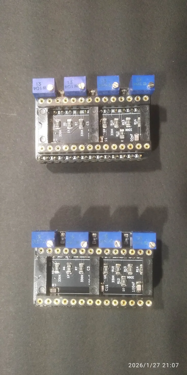
Physical assembly is relatively simple. Recommended order:
- SMD components first.
- Then solder the mounting pins from the bottom side of the PCB.
- Finally solder the DIL28 socket on the top side of the PCB and the trimmer potentiometers.
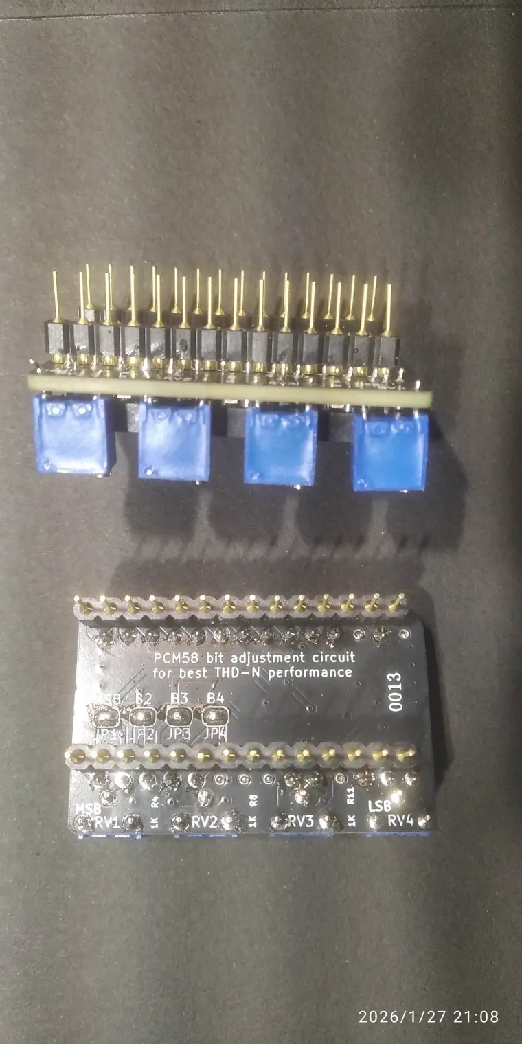
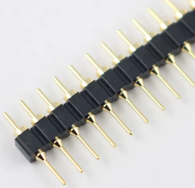
The mounting pins for the socket (installed from the bottom side of the PCB) can be purchased on AliExpress. I did not find them from my distributor, so they are not included in the BOM. Search for:
“2.54mm Pitch Gold Plated Male 40P 1*40 Round Pin Header Strip Hole Single Row Straight Socket Connector”
They look like in the attached photo below.
Links
Visual Analyser:
https://www.sillanumsoft.org/


